


纲要:
把Composition下的SWC分配到System Description 描述的CAN网络的的ECU上。
目录
3. Maping System Signal to Data Element
1. Create System Extract
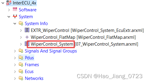
Right click on the project, create "System Info - Elements | System", which will create "07_WiperControl_System.arxml" file.
Configure the category as “SYSTEM_EXTRACT in "Property" Tab. [1]

2. Map SWC to ECU instance
Mapping Components under the "Composition" to ECUs under the "System Description":
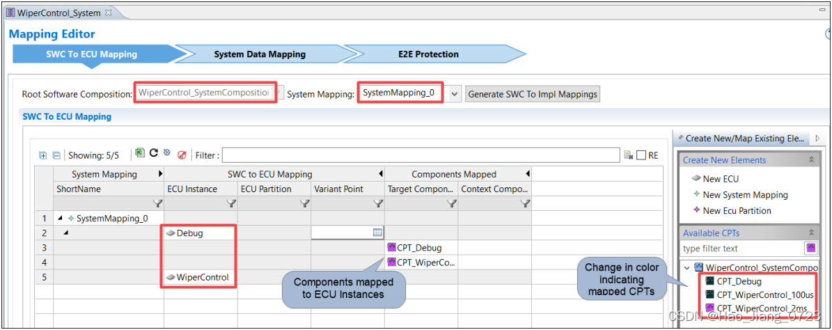
2.1 Right click on the "07_WiperControl_System.arxml" file, open with "SwcToEcuMapping" editor. [2]
2.2 In this "07_WiperControl_System.arxml" file, configure the Top Level Composition to the “WiperControl_Composition”, which then will show all the available components under the composition. ("SwcToEcuMapping" editor 以 WiperControl_System这个Composition为基础显示)[3]
2.3 Create a "System Mapping", which will show all the EUCs belongs to the "System Description". Then you can assign the components to specific ECU as required. [4]
3. Maping System Signal to Data Element
Mapping "System Signal" in System Description to "Data Element" under Compositon.
3.1 Right click on the "07_WiperControl_System.arxml" file, open with "SystemDataMapping" editor.
All the "SWC - Data Element" under the "Compositon" and all "System Signal" under the "System Decription" will show up. ("SystemDataMapping" editor 以 WiperControl_System这个Composition为基础显示)[5][6]
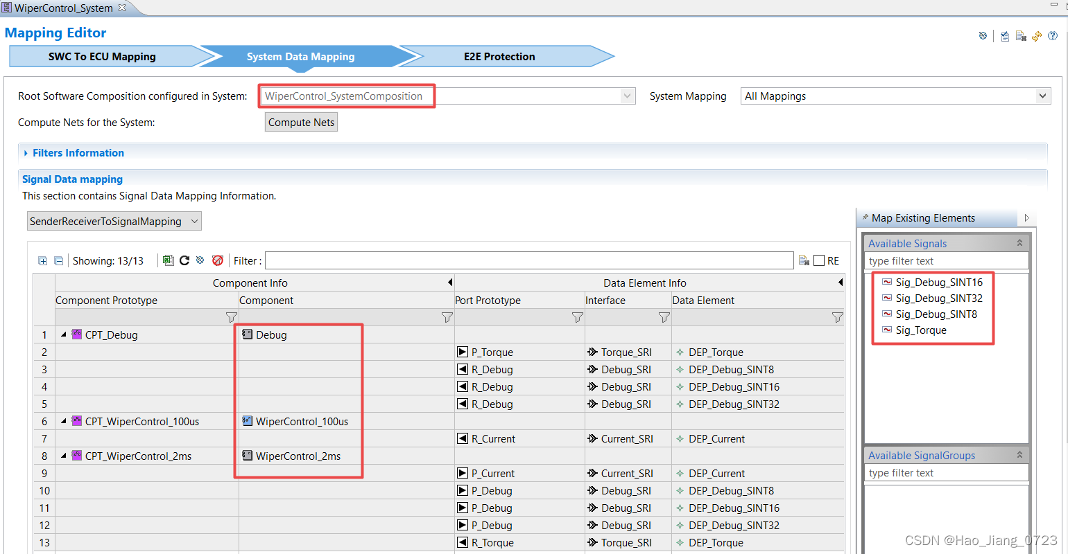
3.2 Drag and drop the "System Signal" to the DataElement to map.[7]
4. Create System Extract
Right click on the "07_WiperControl_System.arxml" file, select "create System Extract". [8]
注:
[0] “SwcToEcuMapping” 和 “SystemDataMapping” 都存储在SystemMapping_0 这个arxml的package里面
[1] 除了“SYSTEM_EXTRACT”,还有ECU_EXTRACT等别的选项,通过这儿可以去判断这个arxml文件是System Extract还是别的
[2] 针对“System Extract” arxml 文件,除了“SwcToEcuMapping”,还有“SystemDataMapping” Editor 这个界面
[3] 所以本质上是按照Composition来分配SWC给ECU的,这也就是为什么project先去创建SWC和Composition,然后才去Import DBC去生成System Description
[4] Composition出SWC,DBC出ECU
[5] “SystemDataMapping” Editor 里面显示的是System Signal,而不是ISignal(ComSignal)
[6] 之所以在ISignal以上抽象出一个System Signal,是因为 ISignal 是跟CAN,LIN这些通讯协议绑定的,而用System Signal而不是ISignal与RTE上面的Data Element相连,就可以实现一个Data Element同时发送给不同的通讯协议,或者同时发给CAN协议下的多个子网络上
[7] 一部分 Data Element 已经在Composition那一步用 Assembly Connector与Composition内部的其他Data Element 相互连好了(Intra-ECU communication), 所以在“SystemDataMapping” 只需要把剩下的,那些需要和外部联系的Data Element 和System Signal给Mapping上即可(Inter-ECU communication through COM stack)
[8] output 是什么?
问:
1. “SystemDataMapping” Editor的界面上Data Element只有一个,如何实现将一个Data Element分别发送到不同的Network下的Signal上?
通过System Signal实现。首先在“SystemDataMapping”将Data Element给Mapping到一个System Signal上,然后在COM模块里面将该System Signal分别assign给不同的ComSignal(ISignal)即可实现
即System Signal 和 ISignal 的数量是不一致的,System Signal 总是小于或等于 ISignal
2. System Extract 和 ECU Extract 有什么区别,看起来System Extract有ECU Extract里面的所有内容,为什么还需要增加ECU Extract这一步?
“07_WiperControl_System.arxml” 这个System Extract文件里面就两大块内容,SwcToEcuMapping 和 SystemSignalMapping。
“WiperControl_System_EcuExtr.arxml” 这个ECU Extract文件也一样,就是SwcToEcuMapping 和 SystemSignalMapping。
之所以分两块,感觉上是因为System Extract arxml文件虽然是针对一个Composition的部署,但是它的SWC可能会部署到好几个ECU上。而ECU Extract arxml仅存储某一个ECU的信息,因为AUTOSAR project最终只会在一个ECU上运行。


 936
936

 被折叠的 条评论
为什么被折叠?
被折叠的 条评论
为什么被折叠?
 到【灌水乐园】发言


