


一、简介
步进电机又称为脉冲电机,基于最基本的电磁铁原理,它是一种可以自由回转的电磁铁,其动作原理是依靠气隙磁导的变化来产生电磁转矩。
步进电机又称为脉冲电机,基于最基本的电磁铁原理,它是一种可以自由回转的电磁铁,其动作原理是依靠气隙磁导的变化来产生电磁转矩。
步进电机是将电脉冲信号,转变为角位移或线位移的开环控制电机,又称为脉冲电机。在非超载的情况下,电机的转速、停止的位置只取决于脉冲信号的频率和脉冲数,而不受负载变化的影响。当步进驱动器接收到一个脉冲信号时,它就可以驱动步进电机按设定的方向转动一个固定的角度,称为“步距角”。
特点
步进电机工作时的位置和速度信号不反馈给控制系统,如果电机工作时的位置和速度信号反馈给控制系统,那么它就属于伺服电机。相对于伺服电机,步进电机的控制相对简单,但不适用于精度要求较高的场合。
二、特性
从步进电机的矩频特性图上可知,步进电机以越快的速度运行,所能输出的转矩越小,否则将会造成失步。每种不同规格的步进电机都有类似的矩频特性曲线,详细图表需要查阅其规格书。
矩频特性
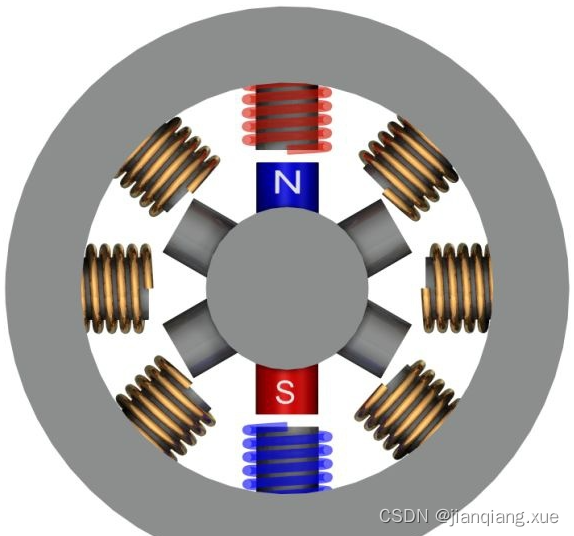
步进电机的磁极数量规格和接线规格很多,为简化问题,我们这里就先只以四相步进电机为例进行讨论。所谓四相,就是说电机内部有4对磁极,此外还有一个公共端(COM)接电源, ABCD是四线的接头。而四相电机的可以向外引出六条接线(两条COM共同接入Vcc),即GND和ABCD,也可以引出五条线,如图所示,所以有成为六线四相制和五线四相制。
这种方式,电机在每个瞬间只有一个线圈导通,消耗电力小但在切换瞬间没有任何的电磁作用转子上,容易造成振动,也容易因为惯性而失步。
三、示例代码
/*************笔记****************
1、CubeMX 定义任意四个引脚,作为ABCD相,并对引脚作出如下配置:
GPlO output level --High
GPIO mode --Output Push Pull
GPIO Pull-up/Pull-down --No pull-up and no pull-down
Maximum output speed --LOW
User label --dianji_A/dianji_B/dianji_C/dianji_D
---------------------------------------------------------
2、本设计采用TTL输出(即高低电平) 低电平--停止 高电平--运行
PB12---电机A相 信号脚
PB13---电机B相 信号脚
PB14---电机C相 信号脚
PB15---电机D相 信号脚
3、
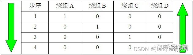
正转 电机导通相序 D-C-B-A
反转 电机导通相序 A-B-C-D
***********************************/
#include "Motor.h"
#include "cmsis_os.h"
#include "stm32f1xx_hal.h"
#define DJ_D(N) HAL_GPIO_WritePin(dianji_D_GPIO_Port,dianji_D_Pin,N==1?GPIO_PIN_SET:GPIO_PIN_RESET)
#define DJ_C(N) HAL_GPIO_WritePin(dianji_C_GPIO_Port,dianji_C_Pin,N==1?GPIO_PIN_SET:GPIO_PIN_RESET)
#define DJ_B(N) HAL_GPIO_WritePin(dianji_B_GPIO_Port,dianji_B_Pin,N==1?GPIO_PIN_SET:GPIO_PIN_RESET)
#define DJ_A(N) HAL_GPIO_WritePin(dianji_A_GPIO_Port,dianji_A_Pin,N==1?GPIO_PIN_SET:GPIO_PIN_RESET)
/******************
函数名:MotorCW
功能:顺时针转动
*******************/
void MotorCW(void)
{
DJ_D(1); //D相运行
DJ_C(0);
DJ_B(0);
DJ_A(0);
osDelay(4); //转速调节
DJ_D(0);
DJ_C(1); //C相运行
DJ_B(0);
DJ_A(0);
osDelay(4); //转速调节
DJ_D(0);
DJ_C(0);
DJ_B(1); //B相运行
DJ_A(0);
osDelay(4); //转速调节
DJ_D(0);
DJ_C(0);
DJ_B(0);
DJ_A(1); //A相运行
osDelay(4); //转速调节
}
/******************
函数名:MotorCCW
功能:逆时针转动
*******************/
void MotorCCW(void)
{
DJ_A(1);
DJ_B(0);
DJ_C(0);
DJ_D(0);
osDelay(4);//转速调节
DJ_A(0);
DJ_B(1);
DJ_C(0);
DJ_D(0);
osDelay(4);//转速调节
DJ_A(0);
DJ_B(0);
DJ_C(1);
DJ_D(0);
osDelay(4);//转速调节
DJ_A(0);
DJ_B(0);
DJ_C(0);
DJ_D(1);
osDelay(4);//转速调节
}
//停止转动
void MotorStop(void)
{
DJ_D(0);
DJ_C(0);
DJ_B(0);
DJ_A(0);
}
/******************
函数名:Open_Door
功能:利用马达模拟开门动作
形参:
返回值:
备注:
*******************/
void Open_Door(void)
{
u8 i = 0;
for(i=0;i<100;i++)
{
MotorCW();
osDelay(10);
}
}
#ifndef _MOTOR_H
#define _MOTOR_H
#include "main.h"
/*
PB12---电机A相信号脚
PB13---电机B相信号脚
PB14---电机C相信号脚
PB15---电机D相信号脚
*/


void MotorCW(void);
void MotorCCW(void);
void MotorStop(void);
void Open_Door(void);
#endif
四、其他
关于实际的步距角
前面所讲述的其实是一个简化模型,真正的步进电机步距角比较小。因为采用了图所示的多齿结构,这种结构类似于游标卡尺的工作原理,所以实际4相步进电机的步距角并非360°/8 = 45°。根据其规格书,本节范例所用的步进电机的步距角是5.625°,如果采用一–二相励磁方式,则可以达到其一半的分辨率
优缺点
优点:
-
电机操作易于通过脉冲信号输入到电机进行控制;
-
不需要反馈电路以返回旋转轴的位置和速度信息(开环控制);
-
由于没有接触电刷而实现了更大的可靠性。
缺点:
-
需要脉冲信号输出电路;
-
当控制不适当的时候,可能会出现同步丢失;
-
由于在旋转轴停止后仍然存在电流而产生热量。


 763
763

 被折叠的 条评论
为什么被折叠?
被折叠的 条评论
为什么被折叠?
 到【灌水乐园】发言


