ros-by-example笔记

前情提要

这是rbx1几章内容的笔记,本来是想借此书来学习ROS的,可是这本书的例程是关于SLAM的,我想要看关于机器手抓取的ROS例程,所以学到半途准备转去学习MoveIt!

4. Networking Between a Robot and a Desktop Computer

笔记本电脑与机器人的网络连接配置。

4.1Time Synchronization

对其电脑与机器的时钟,在电脑与机器人中安装 chrony 即可,运行以下命令行:

$ sudo apt-get install chrony

如此便可以将时钟与互联网服务器的进行对齐,如此便可与各种机器进行时钟对齐

4.2ROS Networking using Zeroconf

由Ubuntu的 Zeroconf 支持,使得在同一局域网下的计算机和机器人可以用各自的hostname进行交流,而不用IP addresses.

$ hostname
my_desktop_name

4.3Testing Connectivity

从电脑端输入以下代码来验证与机器人的连接是否成功:

$ ping my_robot.local

由机器人ping电脑端同样类似(使用ssh进入机器人端)
注意: 若ping的时候显示 “unknown host” error,尝试重启 avahi-daemon :

$ sudo service avahi-daemon restart

4.4Setting the ROS_MASTER_URI and ROS_HOSTNAME Variables

在ROS network中,需要将一个机器设置为 ROS master,且仅在该机器上运行 roscore. 其他机器设置 ROS_MASTER_URI 环境变量,来指向 MASTER host. 通常来说,让谁成为MASTER都可以,但是我们希望将robot作为master,使其不依赖于desktop.

#on the robot
#set the ROS_HOSTNAME to its Zeroconf name
$ export ROS_HOSTNAME=my_robot.local
$ roscore#as master

#on the desktop
$ export ROS_HOSTNAME=my_desktop.local
#set the ROS_MASTER_URI environment variable to point to the master host
$ export ROS_MASTER_URI=http://my_robot.local:11311

#on the desktop
#同步desktop和robot的时间
$ sudo ntpdate -b my_robot.local

#on the desktop
$ rostopic list
#若运行成功,则可见以下两个话题
#/rosout
#/rosout_agg

4.5Opening New Terminals

无论在何处打开了一个新的终端,都需要设置 ROS_HOSTNAME=对应的机器Zeroconf name,并且对于每个nonMaster,还需要设置ROS_MASTER_URI. 所以若是一段时间用的设备不变的话,可以在~/.bashrc中加入此些代码,使得每次打开终端的时候都会自动执行

4.6Running Nodes on both Machines

设置好相互的连接后便可以开始执行节点了,相互连接的机器可以识别所有的topics and services.

# on the desktop
ssh my_robot.local

#on the robot(via ssh)
$ export ROS_HOSTNAME=my_robot.local
$ roscore & #这会返回命令提示符,这样我们就可以启动robot的启动文件,而不必打开另一个ssh会话
$ roslaunch my_robot startup.launch

#on the desktop
$ export ROS_HOSTNAME=my_desktop.local
$ export ROS_MASTER_URI=http://my_robot.local:11311
$ rosrun rviz rviz -d `rospack find rbx1_nav`/nav.rviz

4.7ROS Networking across the Internet

与使用Zeroconf类似,在Internet下连接就是利用fully qualified hostnames or IP addresses.

4.8ROS recap

重点就在于 节点,由C++/Python编写的程序。它可以在特定的话题中分布消息,也可以为其他节点提供服务。

4.9What is a ROS Application

基于Arduino或者stm32的机器人,通常是用C编程的,它们能够控制机器人的硬件,从而直接机器人的行为。而ROS则是将各种行为划分为几个独立的节点,然后让此些节点相互通信。熟悉这种编程方式的话,可以将很多节点的代码重复利用于其他应用中。例如Turtlebot follower application的节点代码可以被利用于使用深度相机和移动底盘的机器人当中。而且ROS是分布式的,意味着可以将一些计算量大的节点置于PC端,low-computation的底层行为置于机器人端。只要机器们在同一网络下,它们就能够通讯。

4.10Installing Packages with SVN, Git, and Mercurial

$ sudo apt-get install git subversion mercurial

常用的操作有两个,第一个是下载软件包,第二个是获取更新,三种系统的命令均不一样。

SVN

#To do the initial checkout and build the package in your personal catkin directory, run the following commands.
$ cd ~/catkin_ws/src
$ svn checkout http://repository/svn/package_name
$ cd ~/catkin_ws
$ catkin_make
$ source devel/setup.bash
$ rospack profile

#To update the package later on, run the commands
$ cd ~/catkin_ws/src/package_name
$ svn update
$ cd ~/catkin_ws
$ catkin_make
$ source devel/setup.bash

Git

$ cd ~/catkin_ws/src
$ git clone git://repository/package_name
$ cd ~/catkin_ws
$ catkin_make
$ source devel/setup.bash
$ rospack profile

$ cd ~/catkin_ws/src/package_name
$ git pull
$ cd ~/catkin_ws
$ catkin_make
$ source devel/setup.bash

Mercurial

$ cd ~/catkin_ws/src
$ hg clone http://repository/package_name
$ cd ~/catkin_ws
$ catkin_make
$ source devel/setup.bash
$ rospack profile

$ cd ~/catkin_ws/src/package_name
$ hg update
$ cd ~/catkin_ws
$ catkin_make
$ source devel/setup.bash

4.11Removing Packages from your Personal catkin Directory

首先删除/src中的包:

$ cd ~/catkin_ws/src
$ \rm -rf my_catkin_package

然后删除所有catkin build objects for all packages,然后再运行catkin_make:

$ cd ~/catkin_ws
$ \rm -rf devel build install
$ catkin_make
$ source devel/setup.bash

#验证package有无被移除
$ roscd my_ros_package
#roscd: No such package 'my_ros_package'

4.12How to Find Third-Party ROS Packages

  1. ROS Wiki 包含了许多ROS packages and stacks,可以根据索引检索,也可以在搜索栏中进行关键字检索
  2. 还可以用命令行检索:
    $ roslocate uri ros_arduino_bridge
    
  3. Browse Software 可以在wiki中游览完整的列表(ROS packages, stacks and repositories as indexed)
  4. Google search

5. Installing THE ROS-BY-EXAMPLE CODE

5.1Installing the Prerequisites

$ sudo apt-get install ros-kinetic-turtlebot-bringup \
ros-kinetic-turtlebot-create-desktop ros-kinetic-openni-* \
ros-kinetic-openni2-* ros-kinetic-freenect-* ros-kinetic-usb-cam \
ros-kinetic-laser-* ros-kinetic-hokuyo-node \
ros-kinetic-audio-common gstreamer0.10-pocketsphinx \
ros-kinetic-pocketsphinx ros-kinetic-slam-gmapping \
ros-kinetic-joystick-drivers python-rosinstall \
ros-kinetic-orocos-kdl ros-kinetic-python-orocos-kdl \
python-setuptools ros-kinetic-dynamixel-motor-* \
libopencv-dev python-opencv ros-kinetic-vision-opencv \
ros-kinetic-depthimage-to-laserscan ros-kinetic-arbotix-* \
ros-kinetic-turtlebot-teleop ros-kinetic-move-base \
ros-kinetic-map-server ros-kinetic-fake-localization \
ros-kinetic-amcl git subversion mercurial

5.2Cloning the rbx1 repository for the first time

$ cd  ~/catkin_ws/src
$ git clone  https://github.com/vanadiumlabs/arbotix_ros.git
$ cd ~/catkin_ws
catkin_make

运行以下代码,确保rbx1是Up-To-Date的:

$ cd ~/catkin_ws/src/rbx1
$ git pull
$ cd ~/catkin_ws
$ catkin_make

6. INSTALLING THE ARBOTIX SIMULATOR

ArbotiX是一个仿真器,用来测试代码。

6.1Installing the Simulator

方法一:

$ sudo apt-get install ros-kinetic-arbotix-*

方法二,利用git源码进行安装:

$ cd  ~/catkin_ws/src
$ git clone  https://github.com/vanadiumlabs/arbotix_ros.git
$ cd ..
$ catkin_make

6.2Testing the Simulator

启动仿真器TurtleBot:

$ roslaunch rbx1_bringup fake_turtlebot.launch
#输出信息应如下所示
process[arbotix-1]: started with pid [23668]
process[robot_state_publisher-2]: started with pid [23669]
[INFO] [1567686794.847364]: ArbotiX being simulated.
[INFO] [1567686794.883537]: Started DiffController (base_controller). Geometry: 0.26m wide, 4100.0 ticks/m.

若使用Pi Robot的模型,则运行如下命令:

$ roslaunch rbx1_bringup fake_pi_robot.launch

下一步,运行 RViz 来观察仿真机器人的运动:

#一个小trick,利用rospack来取得包的路径
$ rosrun rviz rviz -d `rospack find rbx1_nav`/sim.rviz

在终端发布消息,管擦仿真机器人的运动(应该为顺时针的运动):

$ rostopic pub -r 10 /cmd_vel geometry_msgs/Twist '{linear: {x: 0.2, y:
0, z: 0}, angular: {x: 0, y: 0, z: 0.5}}'

停止转动,ctrl+c,然后发布如下信息

$ rostopic pub -1 /cmd_vel geometry_msgs/Twist '{}'

6.3Running the Simulator with Your Own Robot

若有自己机器人的 URDFmodel文件,则可以让它运行于 Arbotix simulator,如turtlebot和Pi Robot一般。

7. CONTROLLING A MOBILE BASE

7.1Units and Coordinate Systems

ROS中的机器所用的坐标系为右手坐标系
右手坐标系右手旋转坐标系
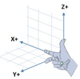
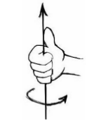
机器人向前,向左转分别对应+x和+y;绕着z轴的正旋转则表示机器人的逆时针旋转。并且ROS使用的是米制系统,所以线速度和角速度的单位分别是m/s, rad/s,对于室内机器人移动,0.2m/s的速度较为适宜。

7.2Levels of Motion Control

运动控制有很多级别的,这些级别代表不同程度的抽象。此处所讲的是从直接控制电机开始,一直到路径规划和SLAM。

Motors, Wheels, and Encoders

大多数差分驱动移动机器人的轮子都有一个编码器,知道车轮的直径和它们之间的距离,编码器刻度可以转换为以米为单位的移动距离或者以弧度旋转的角度。这些内部的运动数据便称为里程计。 当然,由于环境还有里程计来源的不同,机器人实际的位置和运动可能是不一样的。所以才会有SLAM进行运动估计

Motor Controllers and Drivers

在最低级的运动控制中,我们需要一个驱动机器人的马达控制器,它可以以期望的速度转动驱动轮,通常使用内部单位,如每秒编码器滴答声或最大速度的百分比。除了PR2和TurtleBot,核心的ROS packages一般不包含驱动机器人的马达控制器。但是有许多第三方的ROS开发者发布了一些很受欢迎的控制器,如Arduino, ArbotiX等…

The ROS Base Controller

再上升一个级别,就是要在现实世界中获取精确的速度和角速度,通常使用的方法为PID(Proportional Integral Derivative),所利用的是误差的比例, 积分, 微分。驱动器和PID controller 通常组合包含在一个ROS节点中,这个节点名为base controller。base controller通常运行于直接与电机控制器连接的电脑上,并且是启动机器后需要首先运行的节点之一。

base controller发布里程计信息于 /odom 话题中,并且订阅/cmd_vel话题的运动命令。与此同时,controller节点有时还会发布/odom frame到base frame(/base_link or /base_footprint)的transform. 像TurtleBot,则会使用robot_pose_ekf package结合轮子的里程计信息和陀螺仪信息来获得机器人位置和朝向的精确估计,与此同时还会发布/odom到/base_footprint的transform. robot_pose_ekf package的原理是,利用一个6D模型(3D Position and 3D orientation)的扩展卡尔曼滤波器来结合轮子里程计、IMU传感器和视觉里程计的信息以获取机器人精确的3D位姿估计.

在实际应用中,如果不是详细的工程需要,这些硬件方面的东西不用过分关注,ROS都会帮我们搞定。我们的编程可以仅仅关注理想的线速度和角速度,并且我们在ROS交互界面所写的代码应该都可以正常工作于base controller.

Frame-Base Motion using the move_base ROS Package

再上升一个级别,就是允许我们指挥机器人到达一个特定的位置和朝向(相对于某一frame),常用的包为move_base. 总的来说,它可以让机器人移动到指定位置并实现避障功能。它会结合里程计信息以及局部和全局的cost maps,以实现全局路径规划和局部路径规划;同时它还可以控制机器人的线速度、角速度和加速度(速度范围由configuration files设置)。

SLAM using the gmapping and amcl ROS Packages

再再上升一个层次,就是ROS能够让我们使用gmapping创建环境的地图. 雷达扫描的建图效果最好,但也可以使用Kinect or Asus Xtion深度相机来提供一个仿真的雷达扫描。TurtleBot meta-package包含了SLAM所用到的所有工具。

一旦建图成功,便可以调用ROS提供的acml (adaptive Monte Carlo localization自适应蒙特卡洛定位法)包,根据即时的雷达信息和里程计信息来自动地定位机器人.这个包允许操作者任意指定地图的一个位置,然后机器人会自己规划路径到达目的地,并且还能够避障。

Semantic Goal

最后一个高层次,就是机器人可以实现具有语义信息的运动目标,如“去厨房帮我拿个苹果”, 甚至更简单的"帮我拿个苹果"。

Summary

总的来说,整个montion control hierarchy如下所示:
SLAM_Summary

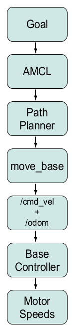
7.3Twisting and Turning with ROS

/cmd_vel 话题常用的消息类型是Twist :

$ rosmsg show geometry_msgs/Twist
#m/s
geometry_msgs/Vector3 linear
float64 x
float64 y
float64 z
#radians/s, 1 radian = 57°
geometry_msgs/Vector3 angular
float64 x
float64 y
float64 z

对于一个在二维平面的机器人,它的线速度只有x方向,角速度只有z轴,只有飞行器或者水下机器人才有六个完整的部分。

Example Twist Messages

如果想要机器人以0.1m/s的速度直线运动,那么Twist消息部分应如下所示:

'{linear: {x: 0.1, y: 0, z: 0}, angular: {x: 0, y: 0, z: 0}}'

如果想要机器人即直行又逆时针转弯:

'{linear: {x: 0.1, y: 0, z: 0}, angular: {x: 0, y: 0, z: 1.0}}'

Monitoring Robot Motion using RViz

$ roslaunch rbx1_bringup fake_turtlebot.launch
$ rosrun rviz rviz -d `rospack find rbx1_nav`/sim.rviz
$ rostopic pub -r 10 /cmd_vel geometry_msgs/Twist '{linear: {x: 0.1, y:
0, z: 0}, angular: {x: 0, y: 0, z: -0.5}}'

最终在Rviz界面中,机器人会如下显示:
Robot在Odometry里程计当中,Keep=50意味着在最久远的箭头消失前,最多存留有50个箭头;Position Tolerance=0.1m and Angle Tolerance=0.05意味着一个新的箭头的更新频率。

停止机器人的运动:

#1. ctrl+c停止发布消息
#2. 发布空的Twist消息
$ rostopic pub -1 /cmd_vel geometry_msgs/Twist '{}'

第二个示例:

下面示例效果是先直行3秒(-l option意思是"publish once"),然后还是无止境地向前逆时针转圈。

$ rostopic pub -1 /cmd_vel geometry_msgs/Twist '{linear: {x: 0.2, y: 0, z: 0}, angular: {x: 0, y: 0, z: 0}}'; rostopic pub -r 10 /cmd_vel geometry_msgs/Twist '{linear: {x: 0.2, y: 0, z: 0}, angular: {x: 0, y: 0, z: 0.5}}'

7.4Calibrating Your Robot’s Odometry

因为地板的摩擦因数不同,所以要对机器进行里程计标定以得到机器人角位移和线位移的修正因子。在进行标定之前,需要安装Orocos kinematics packages:

$ sudo apt-get install ros-kinetic-orocos-kdl ros-kinetic-python-orocos-kdl

rbx1_nav package有两个标定脚本: calibrate_linear and calibrate_angular.py. 第一个通过监听 /odom话题让机器人向前移动1米,并且在离目的地还有1厘米时停下来,可以通过更改脚本或者使用rqt_reconfigure来调整目标距离和移动速度;第二个脚本是通过监听 /odom话题让机器人旋转360°. 接下来两节描述了如何根据结果来调整PID参数

Linear Calibration

本打算使用的机器人turtlebot3,可是树莓派上Ubuntu的网络连接无法显示,无法连接至WIFI,故还是使用Turtlebot2进行实验。

用卷尺拉到至少1米,然后将机器人的标志点与卷尺端对齐,并且让机器人平行于卷尺。对于iRobot Create based TurtleBot,ssh进入机器人的笔记本(因为我只有一个笔记本,所以直接连线操作),运行如下代码:

#启动节点
$ roslaunch rbx1_bringup turtlebot_minimal_create.launch

但却出现如下的错误代码:

process[turtlebot_laptop_battery-8]: started with pid [6698]
[WARN] [1568146010.167950]: Create : robot not connected yet, sci not available
[WARN] [1568146013.174055]: Create : robot not connected yet, sci not available
[WARN] [1568146016.358069]: Invalid OI Mode Reported 15
[WARN] [1568146016.359836]: Invalid Charging Source 252, actual value: 252
[ERROR] [1568146016.430697]: Failed to contact device with error: [Distance, angle displacement too big, invalid readings from robot. Distance: 10.24, Angle: 0.00]. Please check that the Create is powered on and that the connector is plugged into the Create.

[kinect_breaker_enabler-4] process has finished cleanly
log file: /home/jing/.ros/log/82f36ea0-d406-11e9-9222-d85de2302bb5/kinect_breaker_enabler-4*.log
[WARN] [1568146022.842394]: Invalid OI Mode Reported 15
[WARN] [1568146022.843971]: Invalid Charging Source 252, actual value: 252
[WARN] [1568146023.062029]: Invalid OI Mode Reported 108
[WARN] [1568146023.063756]: Invalid Charging Source 111, actual value: 111
[WARN] [1568146023.282010]: Invalid OI Mode Reported 241
[WARN] [1568146023.501217]: Invalid OI Mode Reported 243
[ERROR] [1568146023.574445]: Failed to contact device with error: [Distance, angle displacement too big, invalid readings from robot. Distance: 0.00, Angle: -554.04]. Please check that the Create is powered on and that the connector is plugged into the Create.

原因应该是我用的turtlebot2是kobuki底盘的,与作者所用的Create底盘不一样,所以配置文件也是不一样的,所以会显示Create : robot not connected yet, sci not available,意味着一直没有连接上机器人,因为找不到Create底盘的机器人。

#运行线速度标定节点
$ rosrun rbx1_nav calibrate_linear.py

最后运行rqt_reconfigure:

$ rosrun rqt_reconfigure rqt_reconfigure

选择rqt_configure窗口里的calibrate_linear节点。勾选start_test开始实验(若机器人仍不移动,则反复勾选),理论上机器人应该向前移动1m。遵从以下步骤来获取校正因子:

  1. 记录机器人实际运动的距离actual distance
  2. 记录x = actual distance / target distance
  3. 回到reconfigure的GUI界面,new(odom_linear_scale_correction) =
    x*old(odom_linear_scale_correction)
  4. 将机器人移动至初始位置,再进行标定实验
  5. 重复以上实验直至结果令人满意,1cm/1m的精度大概足矣

最终得到的校正因子需要用合适的launch文件添加至robot’s base controller的参数当中,若使用的是turtlebot, 则在turtlebot.launch中添加一下代码:

# X is my correction factor
<param name="turtlebot_node/odom_linear_scale_correction" value="X"/>

如果用的是ArbotiX base controller,则编辑YAML配置文件,将tick_meter更改为除以修正因子的新值。最终,启动calibration_linear.py script,进入rqt_reconfigure GUI界面,将odom_linear_scale_correction设置为1.0,因为在参数文件中已经进行了校正。

  • 1
    点赞
  • 12
    收藏
    觉得还不错? 一键收藏
  • 2
    评论
当前大多数搞机器人开发的用户所装的ROS是indigo版本,而且是基于Ubuntu14.04的。如果你跑别的版本的rbx代码老出错,不用怀疑,就是代码版本问题!ros by example for indigo volume 1很多地方(包括CSDN)都可以下载,而volume 2则只此一家哦!下面是本书的目录: Contents Preface................................................................................................................vii Printed vs PDF Versions of the Book...............................................................ix 1. Scope of this Volume.......................................................................................1 2. Installing the ros-by-example Code...............................................................3 3. Task Execution using ROS.............................................................................7 3.1 A Fake Battery Simulator.....................................................................................8 3.2 A Common Setup for Running the Examples.....................................................10 3.3 A Brief Review of ROS Actions........................................................................11 3.4 A Patrol Bot Example.........................................................................................12 3.5 The Patrol Bot using a Standard Script...............................................................13 3.6 Problems with the Script Approach....................................................................16 3.7 SMACH or Behavior Trees?..............................................................................17 3.8 SMACH: Tasks as State Machines.....................................................................17 3.8.1 SMACH review.......................................................................................................18 3.8.2 Patrolling a square using SMACH..........................................................................19 3.8.3 Testing SMACH navigation in the ArbotiX simulator............................................23 3.8.4 Accessing results from a SimpleActionState...........................................................26 3.8.5 SMACH Iterators.....................................................................................................27 3.8.6 Executing commands on each transition.................................................................30 3.8.7 Interacting with ROS topics and services................................................................31 3.8.8 Callbacks and Introspection.....................................................................................36 3.8.9 Concurrent tasks: Adding the battery check to the patrol routine...........................36 3.8.10 Comments on the battery checking Patrol Bot......................................................44 3.8.11 Passing user data between states and state machines............................................44 3.8.12 Subtasks and hierarchical state machines..............................................................48 3.8.13 Adding the battery check to the house cleaning robot...........................................54 3.8.14 Drawbacks of state machines................................................................................54 3.9 Behavior Trees...................................................................................................55 3.9.1 Behavior Trees versus Hierarchical State Machines...............................................56 3.1.2 Key properties of behavior trees..............................................................................57 3.9.3 Building a behavior tree..........................................................................................58 3.9.4 Selectors and sequences...........................................................................................60 3.9.5 Customizing behaviors using decorators (meta-behaviors).....................................61 3.10 Programming with Behavior Trees and ROS....................................................63 3.10.1 Installing the pi_trees library.................................................................................63 3.10.2 Basic components of the pi_trees library..............................................................63 3.10.3 ROS-specific behavior tree classes........................................................................68 3.10.4 A Patrol Bot example using behavior trees..........................................................72 3.10.5 A housing cleaning robot using behavior trees.....................................................79 3.10.6 Parallel tasks..........................................................................................................85 3.10.7 Adding and removing tasks...................................................................................87 4. Creating a URDF Model for your Robot....................................................89 4.1 Start with the Base and Wheels..........................................................................90 4.1.1 The robot_state_publisher and joint_state_publisher nodes....................................91 4.1.2 The base URDF/Xacro file......................................................................................92 4.1.3 Alternatives to using the /base_footprint frame......................................................97 4.1.4 Adding the base to the robot model.........................................................................97 4.1.5 Viewing the robot's transform tree..........................................................................98 4.1.6 Using a mesh for the base........................................................................................99 4.2 Simplifying Your Meshes.................................................................................104 4.3 Adding a Torso.................................................................................................104 4.3.1 Modeling the torso.................................................................................................105 4.3.2 Attaching the torso to the base..............................................................................106 4.3.3 Using a mesh for the torso.....................................................................................107 4.3.4 Adding the mesh torso to the mesh base...............................................................108 4.4 Measure, Calculate and Tweak.........................................................................110 4.5 Adding a Camera..............................................................................................110 4.5.1 Placement of the camera........................................................................................111 4.5.2 Modeling the camera.............................................................................................112 4.5.3 Adding the camera to the torso and base...............................................................114 4.5.4 Viewing the transform tree with torso and camera................................................115 4.5.5 Using a mesh for the camera.................................................................................116 4.5.6 Using an Asus Xtion Pro instead of a Kinect........................................................118 4.6 Adding a Laser Scanner (or other Sensors)......................................................119 4.6.1 Modeling the laser scanner....................................................................................119 4.6.2 Attaching a laser scanner (or other sensor) to a mesh base...................................120 4.6.3 Configuring the laser node launch file..................................................................121 4.7 Adding a Pan and Tilt Head..............................................................................122 4.7.1 Using an Asus Xtion Pro instead of a Kinect........................................................124 4.7.2 Modeling the pan-and-tilt head..............................................................................124 4.7.3 Figuring out rotation axes......................................................................................127 4.7.4 A pan and tilt head using meshes on Pi Robot......................................................128 4.7.5 Using an Asus Xtion Pro mesh instead of a Kinect on Pi Robot...........................129 4.8 Adding One or Two Arms................................................................................129 4.8.1 Placement of the arm(s).........................................................................................130 4.8.2 Modeling the arm...................................................................................................130 4.8.3 Adding a gripper frame for planning.....................................................................133 4.8.4 Adding a second arm.............................................................................................134 4.8.5 Using meshes for the arm servos and brackets......................................................136 4.9 Adding a Telescoping Torso to the Box Robot.................................................138 4.10 Adding a Telescoping Torso to Pi Robot........................................................139 4.11 A Tabletop One-Arm Pi Robot.......................................................................140 4.12 Testing your Model with the ArbotiX Simulator............................................142 4.12.1 A fake Box Robot................................................................................................142 4.12.2 A fake Pi Robot...................................................................................................145 4.13 Creating your own Robot Description Package..............................................145 4.13.1 Using rosbuild......................................................................................................145 4.13.2 Using catkin.........................................................................................................146 4.13.3 Copying files from the rbx2_description package...............................................147 4.13.4 Creating a test launch file....................................................................................147 5. Controlling Dynamixel Servos: Take 2......................................................149 5.1 Installing the ArbotiX Packages.......................................................................149 5.2 Launching the ArbotiX Nodes..........................................................................150 5.3 The ArbotiX Configuration File.......................................................................154 5.4 Testing the ArbotiX Joint Controllers in Fake Mode........................................160 5.5 Testing the Arbotix Joint Controllers with Real Servos....................................162 5.6 Relaxing All Servos..........................................................................................165 5.7 Enabling or Disabling All Servos.....................................................................168 6. Robot Diagnostics........................................................................................169 6.1 The DiagnosticStatus Message.........................................................................170 6.2 The Analyzer Configuration File......................................................................171 6.3 Monitoring Dynamixel Servo Temperatures....................................................172 6.3.1 Monitoring the servos for a pan-and-tilt head.......................................................172 6.3.2 Viewing messages on the /diagnostics topic.........................................................175 6.3.3 Protecting servos by monitoring the /diagnostics topic.........................................177 6.4 Monitoring a Laptop Battery............................................................................181 6.5 Creating your Own Diagnostics Messages.......................................................182 6.6 Monitoring Other Hardware States...................................................................188 7. Dynamic Reconfigure..................................................................................191 7.1 Adding Dynamic Parameters to your own Nodes.............................................192 7.1.1 Creating the .cfg file..............................................................................................192 7.1.2 Making the .cfg file executable.............................................................................193 7.1.3 Configuring the CMakeLists.txt file......................................................................194 7.1.4 Building the package.............................................................................................194 7.2 Adding Dynamic Reconfigure Capability to the Battery Simulator Node........194 7.3 Adding Dynamic Reconfigure Client Support to a ROS Node.........................198 7.4 Dynamic Reconfigure from the Command Line...............................................201 8. Multiplexing Topics with mux & yocs.......................................................203 8.1 Configuring Launch Files to Use mux Topics..................................................204 8.2 Testing mux with the Fake TurtleBot...............................................................205 8.3 Switching Inputs using mux Services...............................................................206 8.4 A ROS Node to Prioritize mux Inputs..............................................................207 8.5 The YOCS Controller from Yujin Robot..........................................................210 8.5.1 Adding input sources.............................................................................................213 9. Head Tracking in 3D...................................................................................215 9.1 Tracking a Fictional 3D Target.........................................................................216 9.2 Tracking a Point on the Robot..........................................................................217 9.3 The 3D Head Tracking Node............................................................................220 9.3.1 Real or fake head tracking.....................................................................................220 9.1.2 Projecting the target onto the camera plane...........................................................221 9.4 Head Tracking with Real Servos......................................................................224 9.4.1 Real servos and fake target....................................................................................225 9.4.2 Real servos, real target...........................................................................................226 9.4.3 The nearest_cloud.py node and launch file...........................................................228 10. Detecting and Tracking AR Tags.............................................................233 10.1 Installing and Testing the ar_track_alvar Package..........................................234 10.1.1 Creating your own AR Tags................................................................................234 10.1.2 Generating and printing the AR tags...................................................................236 10.1.3 Launching the camera driver and ar_track_alvar node.......................................236 10.1.4 Testing marker detection.....................................................................................238 10.1.5 Understanding the /ar_pose_marker topic...........................................................238 10.1.6 Viewing the markers in RViz..............................................................................240 10.2 Accessing AR Tag Poses in your Programs....................................................240 10.2.1 The ar_tags_cog.py script....................................................................................240 10.2.2 Tracking the tags with a pan-and-tilt head..........................................................244 10.3 Tracking Multiple Tags using Marker Bundles..............................................245 10.4 Following an AR Tag with a Mobile Robot....................................................245 10.4.1 Running the AR follower script on a TurtleBot .................................................248 10.5 Exercise: Localization using AR Tags............................................................249 11. Arm Navigation using MoveIt!.................................................................251 11.1 Do I Need a Real Robot with a Real Arm?.....................................................252 11.2 Degrees of Freedom.......................................................................................252 11.3 Joint Types.....................................................................................................253 11.4 Joint Trajectories and the Joint Trajectory Action Controller.........................254 11.5 Forward and Inverse Arm Kinematics............................................................257 11.6 Numerical versus Analytic Inverse Kinematics..............................................258 11.7 The MoveIt! Architecture...............................................................................258 11.8 Installing MoveIt!...........................................................................................260 11.9 Creating a Static URDF Model for your Robot .............................................261 11.10 Running the MoveIt! Setup Assistant...........................................................262 11.10.1 Load the robot's URDF model...........................................................................263 11.2.2 Generate the collision matrix.............................................................................264 11.10.3 Add the base_odom virtual joint.......................................................................264 11.10.4 Adding the right arm planning group................................................................265 11.10.5 Adding the right gripper planning group...........................................................269 11.10.6 Defining robot poses..........................................................................................271 11.10.7 Defining end effectors.......................................................................................273 11.10.8 Defining passive joints......................................................................................273 11.10.9 Generating the configuration files.....................................................................273 11.11 Configuration Files Created by the MoveIt! Setup Assistant........................275 11.11.1 The SRDF file (robot_name.srdf)......................................................................275 11.11.2 The fake_controllers.yaml file...........................................................................276 11.11.3 The joint_limits.yaml file..................................................................................277 11.11.4 The kinematics.yaml file...................................................................................278 11.12 The move_group Node and Launch File.......................................................280 11.13 Testing MoveIt! in Demo Mode...................................................................280 11.13.1 Exploring additional features of the Motion Planning plugin...........................284 11.13.2 Re-running the Setup Assistant at a later time..................................................285 11.14 Testing MoveIt! from the Command Line....................................................286 11.15 Determining Joint Configurations and End Effector Poses...........................289 11.16 Using the ArbotiX Joint Trajectory Action Controllers................................292 11.16.1 Testing the ArbotiX joint trajectory action controllers in simulation...............292 11.16.2 Testing the ArbotiX joint trajectory controllers with real servos......................300 11.17 Configuring MoveIt! Joint Controllers.........................................................301 11.17.1 Creating the controllers.yaml file......................................................................302 11.17.2 Creating the controller manager launch file......................................................304 11.18 The MoveIt! API..........................................................................................305 11.19 Forward Kinematics: Planning in Joint Space..............................................306 11.20 Inverse Kinematics: Planning in Cartesian Space.........................................314 11.21 Pointing at or Reaching for a Visual Target..................................................322 11.22 Setting Constraints on Planned Trajectories.................................................324 11.22.1 Executing Cartesian Paths.................................................................................324 11.22.2 Setting other path constraints............................................................................330 11.23 Adjusting Trajectory Speed..........................................................................333 11.24 Adding Obstacles to the Planning Scene......................................................337 11.25 Attaching Objects and Tools to the Robot....................................................346 11.26 Pick and Place..............................................................................................348 11.27 Adding a Sensor Controller..........................................................................360 11.28 Running MoveIt! on a Real Arm..................................................................363 11.28.1 Creating your own launch files and scripts.......................................................364 11.28.2 Running the robot's launch files........................................................................364 11.2.3 Forward kinematics on a real arm.....................................................................365 11.28.4 Inverse kinematics on a real arm.......................................................................366 11.28.5 Cartesian paths on a real arm.............................................................................367 11.28.6 Pick-and-place on a real arm.............................................................................367 11.28.7 Pointing at or reaching for a visual target..........................................................367 11.29 Creating a Custom Fast IK Plugin................................................................368 12. Gazebo: Simulating Worlds and Robots.................................................375 12.1 Installing Gazebo............................................................................................376 12.2 Hardware Graphics Acceleration....................................................................377 12.3 Installing the ROS Gazebo Packages..............................................................378 12.4 Installing the Kobuki ROS Packages..............................................................379 12.5 Installing the UBR-1 Files..............................................................................379 12.6 Using the Gazebo GUI...................................................................................379 12.7 Missing Model Bug in Gazebo 1.9.................................................................381 12.8 Testing the Kobuki Robot in Gazebo..............................................................383 12.8.1 Accessing simulated sensor data.........................................................................385 12.8.2 Adding safety control to the Kobuki...................................................................389 12.8.3 Running the nav_square.py script from Volume 1..............................................391 12.9 Loading Other Worlds and Objects................................................................392 12.10 Testing the UBR-1 Robot in Gazebo............................................................393 12.10.1 UBR-1 joint trajectories.....................................................................................394 12.1.2 The UBR-1 and MoveIt!....................................................................................395 12.11 Real Pick-and-Place using the UBR-1 Perception Pipeline..........................397 12.11.1 Limitations of depth cameras............................................................................398 12.11.2 Running the demo..............................................................................................399 12.11.3 Understanding the real_pick_and_place.py script.............................................404 12.12 Running Gazebo Headless + RViz...............................................................407 13. Rosbridge: Building a Web GUI for your Robot...................................411 13.1 Installing the rosbridge Packages...................................................................411 13.2 Installing the mjpeg_sever Package................................................................412 13.3 Installing a Simple Web Server (mini-httpd)..................................................415 13.4 Starting mini-httpd, rosbridge and mjpeg_server............................................416 13.5 A Simple rosbridge HTML/Javascript GUI....................................................417 13.6 Testing the GUI with a Fake TurtleBot..........................................................420 13.7 Testing the GUI with a Real Robot.................................................................420 13.8 Viewing the Web GUI on another Device on your Network..........................421 13.9 Using the Browser Debug Console.................................................................421 13.10 Understanding the Simple GUI.....................................................................423 13.10.1 The HTML layout: simple_gui.html.................................................................423 13.1.2 The JavaScript code: simple_gui.js...................................................................428 13.11 A More Advanced GUI using jQuery, jqWidgets and KineticJS..................438 13.12 Rosbridge Summary.....................................................................................443 Appendix: Plug and Play USB Devices for ROS: Creating udev Rules......445 13.13 Adding yourself to the dialout Group...........................................................445 13.14 Determining the Serial Number of a Device.................................................446 13.15 UDEV Rules.................................................................................................447 13.16 Testing a UDEV Rule...................................................................................448 13.17 Using a UDEV Device Name in a ROS Configuration File..........................448

“相关推荐”对你有帮助么?

  • 非常没帮助
  • 没帮助
  • 一般
  • 有帮助
  • 非常有帮助
提交
评论 2
添加红包

请填写红包祝福语或标题

红包个数最小为10个

红包金额最低5元

当前余额3.43前往充值 >
需支付:10.00
成就一亿技术人!
领取后你会自动成为博主和红包主的粉丝 规则
hope_wisdom
发出的红包
实付
使用余额支付
点击重新获取
扫码支付
钱包余额 0

抵扣说明:

1.余额是钱包充值的虚拟货币,按照1:1的比例进行支付金额的抵扣。
2.余额无法直接购买下载,可以购买VIP、付费专栏及课程。

余额充值