


准备材料:
Arduino Uno * 1
按键*2
电阻(860Ω)*2
舵机*1
电路连线:
注意:按键要接上拉电阻。否则电平会随机变化,导致检测错误。
实验代码:
double pi = 3.14159265354;
double t = 0.0;       //单位:s
double dt = 0.0;    //单位:s

unsigned long nLastTime = 0;
int pulse = 0;
float w = 0.1;

int pwm_channel = 3;
int freq_channel = 7;
int begin_channel = 5;

int adn_pmax = 254;
int adn_pmin = 128;
int delta_adn_pwm = 0;
int adn_pmid = 0;
int pwm_out_min = 180;
int pwm_out_max = 206;
int pwm_out_mid = 193;

float cnt =  1.0;
float last_cnt;
int stage = 0;

void setup() {
  // put your setup code here, to run once:
  Serial.begin(115200);

  pinMode(pwm_channel,OUTPUT);
  pinMode(freq_channel,INPUT);
  pinMode(begin_channel,INPUT);

  nLastTime = micros();

}

void loop() {
  // put your main code here, to run repeatedly:

  int freq_val  = digitalRead(freq_channel);
  int begin_val = digitalRead(begin_channel);

  if(stage == 0)
    if(freq_val == LOW){
      stage = 1;
    }
  if(stage == 1)
    if(freq_val == HIGH){
      cnt++;
      stage = 0;
  }

  if(w<1){
    w = (cnt / 10);
  }
  else if( (w>=1) && (w<10) ){
     if(last_cnt != cnt){
        w = w + 1.0;
     }
  }
  else{
     if(last_cnt != cnt){
        w = w + 10.0;
     }
  }

  last_cnt = cnt;

//  Serial.print(cnt); Serial.print('\t');
  double nNowTime = micros();     //单位:微秒
  dt = (nNowTime - nLastTime)/1e6;
  t = t + dt + 6.6e-5;
  nLastTime = micros();     //单位:微秒

  Serial.print(w); Serial.print('\t');
  if(begin_val == LOW){
    pulse = int(pwm_out_mid + 0.5*(pwm_out_max-pwm_out_min)*sin(2*pi*w*t));
    constrant();
  }
  else{
    pulse = pwm_out_mid;
  }

  analogWrite(pwm_channel,pulse);

  Serial.print(pulse); Serial.print('\t');

  Serial.print(dt); Serial.print('\t');

  Serial.println(t,6);

}

void constrant(void){
  if(pulse>=pwm_out_max)
    pulse = pwm_out_max;
  if(pulse<=pwm_out_min)
    pulse = pwm_out_min;
}
实验要点:
1.按键计数不仅要判断是否按下,还要判断是否抬起,否则计数器会疯狂累加。
2.特定频率正弦信号输出,Ts在Te之后,越靠近Te越好,dt的误差越小。图中代码dt的误差为。”Ts = micros()“ 记录当前时刻的定时器数值,直到下一个周期“Te = micro()”之间所有语句的执行时间都被计算在内。因此误差为两条“dt = double((Te - Ts)/1e6);t = t + dt;”语句执行的时间,加上6.6e-5正好补偿这两条语句的误差。
实验结果:
通过串口将输出的数据在matlab上画出来。结果如下:

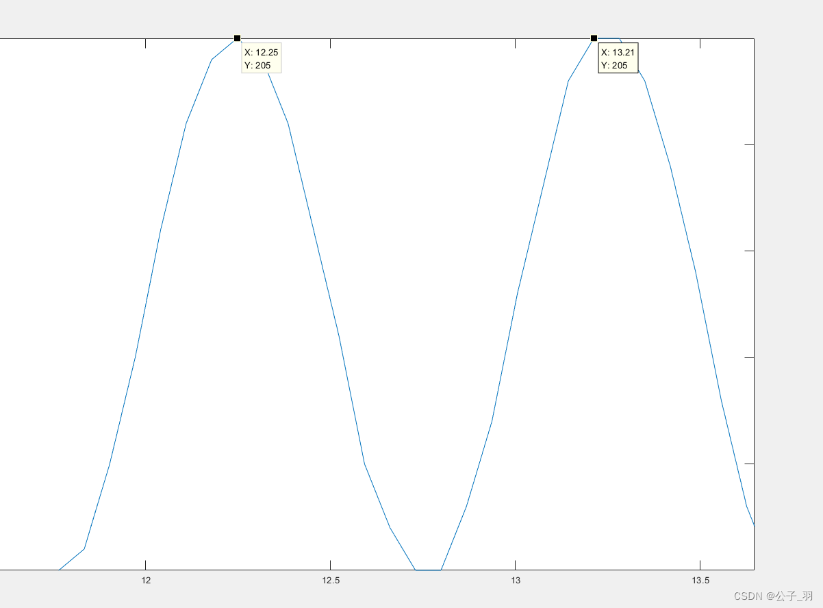
上图为1Hz的正弦信号输出,可以看到两个峰值之间的时间差在1s左右。第二个峰不够尖是量化误差导致。


 3185
3185


 被折叠的 条评论
为什么被折叠?
被折叠的 条评论
为什么被折叠?
 到【灌水乐园】发言


