


需要参数:
1、做计划的CT模拟图像的文件夹路劲
2、治疗计划的等中心点(300A,012C) Isocenter Position
3、生成DRR图像的角度
代码如下(因为需要C#调用接口,所以该示例返回了生成DRR图像的像素值):
#ifndef __INTERFACE_H__
#define __INTERFACE_H__
# define xSize 512
# define ySize 512
# define zSize 1

#if defined(_WIN32)
#ifdef REG_COMPILE_LIBRARY
#define REG_CAPI_EXPORT __declspec(dllexport)
#else
#define REG_CAPI_EXPORT __declspec(dllimport)
#endif
#else
#define REG_CAPI_EXPORT
#endif

#ifdef __cplusplus
extern "C"
{
#endif
	struct DRRImage_Input
	{
		char* path;
		float Angle;
		float IsoCenterPosition[3];
	};
	struct DRRImage_Output
	{

		int Size[2];
		float Spacing[2];
		short ImageData[xSize * ySize * zSize];
	};
	REG_CAPI_EXPORT int GetDRRImagePixel(DRRImage_Input* input, DRRImage_Output* output);
#ifdef __cplusplus
}
#endif

#endif
#include "UtilHelper.h"
#include "itkResampleImageFilter.h"
#include "itkCenteredEuler3DTransform.h"
#include "itkRescaleIntensityImageFilter.h"
#include "itkGDCMImageIO.h"
#include "itkGDCMSeriesFileNames.h"
#include "itkImageSeriesReader.h"
#include "itkNumericSeriesFileNames.h"
#include "itkRayCastInterpolateImageFunction.h"
int GetDRRImagePixel(DRRImage_Input* input, DRRImage_Output* output)
{
float rx = -90.;
float ry = 0.;
float rz = input->Angle;
float tx = 0.;
float ty = 0.;
float tz = 0.;
float cx = 0.;
float cy = 0.;
float cz = 0.;
float sid = -1000.;
float sx = 1.;
float sy = 1.;
int dx = xSize;
int dy = ySize;
int dz = zSize;
float o2Dx = 0;
float o2Dy = 0;
double threshold = 0;
std::cout << "Input image: " << input->path << std::endl;
std::cout << "DRR Angle: " << input->Angle << std::endl;
std::cout << "IsoCenterPosition[0]: " << input->IsoCenterPosition[0] << std::endl;
std::cout << "IsoCenterPosition[1]: " << input->IsoCenterPosition[1] << std::endl;
std::cout << "IsoCenterPosition[2]: " << input->IsoCenterPosition[2] << std::endl;
// Set these values from the treatment plan
float isoCenterX = input->IsoCenterPosition[0];
float isoCenterY = input->IsoCenterPosition[1];
float isoCenterZ = input->IsoCenterPosition[2];
// Software Guide : BeginLatex
//
// Although we generate a 2D projection of the 3D volume for the
// purposes of the interpolator both images must be three dimensional.
//
// Software Guide : EndLatex
// Software Guide : BeginCodeSnippet
constexpr unsigned int Dimension = 3;
using InputPixelType = short;
using InputImageType = itk::Image<InputPixelType, Dimension>;
InputImageType::Pointer image;
// Software Guide : EndCodeSnippet
// Software Guide : BeginLatex
//
// For the purposes of this example we assume the input volume has
// been loaded into an \code{itk::Image image}.
//
// Software Guide : EndLatex
/*
using ReaderType = itk::ImageFileReader< InputImageType >;
ReaderType::Pointer reader = ReaderType::New();
reader->SetFileName( input_name );
*/
//定义像素类型,图像类型,三维有符号数,定义指针
typedef signed short PixelType;
typedef itk::Image< PixelType, Dimension > ImageType;
typedef itk::ImageSeriesReader< ImageType > ReaderType;
//声明读、写DICOM图像的itk::GDCMImageIO对象
//itk::GDCMSeriesFileNames对象将生成并将构成所有体数据的切片的文件名进行排序
typedef itk::GDCMImageIO ImageIOType;
typedef itk::GDCMSeriesFileNames NamesGeneratorType;
ImageIOType::Pointer gdcmIO = ImageIOType::New();
NamesGeneratorType::Pointer namesGenerator = NamesGeneratorType::New();
//设置读取路径
//用文件名发生器生成被读的文件名和被写的文件名
namesGenerator->SetInputDirectory(input->path);
const ReaderType::FileNamesContainer& filenames = namesGenerator->GetInputFileNames();
//设置DICOM图像IO对象和被读的文件名的列表
ReaderType::Pointer reader = ReaderType::New();
reader->SetImageIO(gdcmIO);
reader->SetFileNames(filenames);
try
{
reader->Update();
}
catch (itk::ExceptionObject& err)
{
std::cerr << "ERROR: ExceptionObject caught !" << std::endl;
std::cerr << err << std::endl;
return EXIT_FAILURE;
}
image = reader->GetOutput();
// Print out the details of the input volume
std::cout << "Image Spacing:" << image->GetSpacing() << std::endl;
std::cout << "Image BufferedRegion:" << image->GetBufferedRegion() << std::endl;
std::cout << "Image Origin:" << image->GetOrigin() << std::endl;
// Software Guide : BeginLatex
//
// Creation of a \code{ResampleImageFilter} enables coordinates for
// each of the pixels in the DRR image to be generated. These
// coordinates are used by the \code{RayCastInterpolateImageFunction}
// to determine the equation of each corresponding ray which is cast
// through the input volume.
//
// Software Guide : EndLatex
// Software Guide : BeginCodeSnippet
using FilterType = itk::ResampleImageFilter<InputImageType, InputImageType>;
auto filter = FilterType::New();
filter->SetInput(image);
filter->SetDefaultPixelValue(0);
// Software Guide : EndCodeSnippet
// Software Guide : BeginLatex
//
// An Euler transformation is defined to position the input volume.
// The \code{ResampleImageFilter} uses this transform to position the
// output DRR image for the desired view.
//
// Software Guide : EndLatex
// Software Guide : BeginCodeSnippet
using TransformType = itk::CenteredEuler3DTransform<double>;
auto transform = TransformType::New();
transform->SetComputeZYX(true);
TransformType::OutputVectorType translation;
translation[0] = tx;
translation[1] = ty;
translation[2] = tz;
// constant for converting degrees into radians
const double dtr = (std::atan(1.0) * 4.0) / 180.0;
transform->SetTranslation(translation);
transform->SetRotation(dtr * rx, dtr * ry, dtr * rz);
InputImageType::PointType imOrigin = image->GetOrigin();
InputImageType::SpacingType imRes = image->GetSpacing();
using InputImageRegionType = InputImageType::RegionType;
using InputImageSizeType = InputImageRegionType::SizeType;
InputImageRegionType imRegion = image->GetBufferedRegion();
InputImageSizeType imSize = imRegion.GetSize();
imOrigin[0] += isoCenterX;
imOrigin[1] += isoCenterY;
imOrigin[2] += isoCenterZ;
TransformType::InputPointType center;
center[0] = cx + isoCenterX;
center[1] = cy + isoCenterY;
center[2] = cz + isoCenterZ;
transform->SetCenter(center);
std::cout << "Image size: " << imSize[0] << ", " << imSize[1] << ", "
<< imSize[2] << std::endl
<< " resolution: " << imRes[0] << ", " << imRes[1] << ", "
<< imRes[2] << std::endl
<< " origin: " << imOrigin[0] << ", " << imOrigin[1] << ", "
<< imOrigin[2] << std::endl
<< " center: " << center[0] << ", " << center[1] << ", "
<< center[2] << std::endl
<< "Transform: " << transform << std::endl;
// Software Guide : EndCodeSnippet
// Software Guide : BeginLatex
//
// The \code{RayCastInterpolateImageFunction} is instantiated and passed the
// transform object. The \code{RayCastInterpolateImageFunction} uses this
// transform to reposition the x-ray source such that the DRR image
// and x-ray source move as one around the input volume. This coupling
// mimics the rigid geometry of the x-ray gantry.
//
// Software Guide : EndLatex
// Software Guide : BeginCodeSnippet
using InterpolatorType =
itk::RayCastInterpolateImageFunction<InputImageType, double>;
auto interpolator = InterpolatorType::New();
interpolator->SetTransform(transform);
// Software Guide : EndCodeSnippet
// Software Guide : BeginLatex
//
// We can then specify a threshold above which the volume's
// intensities will be integrated.
//
// Software Guide : EndLatex
// Software Guide : BeginCodeSnippet
interpolator->SetThreshold(threshold);
// Software Guide : EndCodeSnippet
// Software Guide : BeginLatex
//
// The ray-cast interpolator needs to know the initial position of the
// ray source or focal point. In this example we place the input
// volume at the origin and halfway between the ray source and the
// screen. The distance between the ray source and the screen
// is the "source to image distance" \code{sid} and is specified by
// the user.
//
// Software Guide : EndLatex
// Software Guide : BeginCodeSnippet
InterpolatorType::InputPointType focalpoint;
focalpoint[0] = isoCenterX;
focalpoint[1] = isoCenterY;
focalpoint[2] = sid;
interpolator->SetFocalPoint(focalpoint);
// Software Guide : EndCodeSnippet
std::cout << "Focal Point: " << focalpoint[0] << ", " << focalpoint[1]
<< ", " << focalpoint[2] << std::endl;
// Software Guide : BeginLatex
//
// Having initialised the interpolator we pass the object to the
// resample filter.
//
// Software Guide : EndLatex
// Software Guide : BeginCodeSnippet
interpolator->Print(std::cout);
filter->SetInterpolator(interpolator);
filter->SetTransform(transform);
// Software Guide : EndCodeSnippet
// Software Guide : BeginLatex
//
// The size and resolution of the output DRR image is specified via the
// resample filter.
//
// Software Guide : EndLatex
// Software Guide : BeginCodeSnippet
// setup the scene
InputImageType::SizeType size;
size[0] = dx; // number of pixels along X of the 2D DRR image
size[1] = dy; // number of pixels along Y of the 2D DRR image
size[2] = dz; // only one slice
filter->SetSize(size);
InputImageType::SpacingType spacing;
spacing[0] = sx; // pixel spacing along X of the 2D DRR image [mm]
spacing[1] = sy; // pixel spacing along Y of the 2D DRR image [mm]
spacing[2] = 1.0; // slice thickness of the 2D DRR image [mm]
filter->SetOutputSpacing(spacing);
// Software Guide : EndCodeSnippet
std::cout << "Output image size: " << size[0] << ", " << size[1] << ", "
<< size[2] << std::endl;
std::cout << "Output image spacing: " << spacing[0] << ", " << spacing[1]
<< ", " << spacing[2] << std::endl;
// Software Guide : BeginLatex
//
// In addition the position of the DRR is specified. The default
// position of the input volume, prior to its transformation is
// half-way between the ray source and screen and unless specified
// otherwise the normal from the "screen" to the ray source passes
// directly through the centre of the DRR.
//
// Software Guide : EndLatex
// Software Guide : BeginCodeSnippet
double origin[Dimension];
origin[0] = isoCenterX + o2Dx - sx * (static_cast<double>(dx) - 1.) / 2.;
origin[1] = isoCenterY + o2Dy - sy * (static_cast<double>(dy) - 1.) / 2.;
origin[2] = isoCenterZ;
filter->SetOutputOrigin(origin);
// Software Guide : EndCodeSnippet
std::cout << "Output image origin: " << origin[0] << ", " << origin[1]
<< ", " << origin[2] << std::endl;
filter->Update();
std::cout << filter->GetOutput()->GetBufferPointer() << std::endl;
short* inptr = filter->GetOutput()->GetBufferPointer();
const int n = dx * dy * dz;
//config->imageData[n];
for (int i = 0; i < n; ++i)
{
output->ImageData[i] = inptr[i];
}
output->Size[0] = size[0];
output->Size[1] = size[1];
output->Spacing[0] = spacing[0];
output->Spacing[1] = spacing[1];
return EXIT_SUCCESS;
}得到的图像示例(0度):
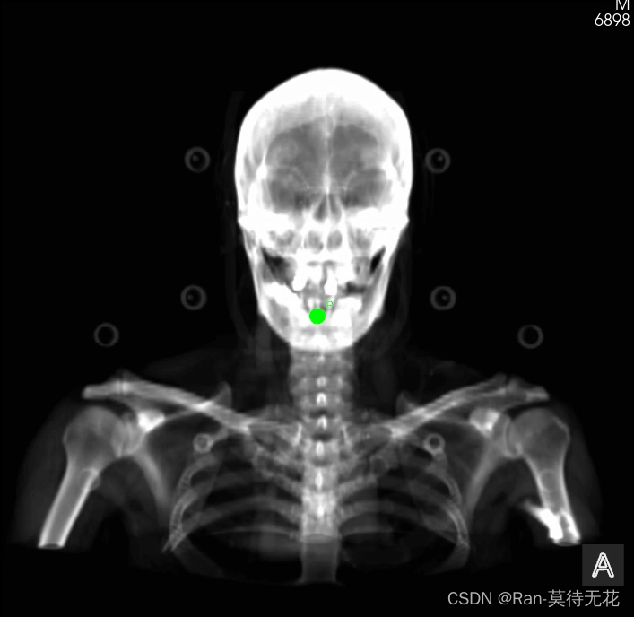
图像中的绿点就是治疗等中心点(坐标【0,0,0】)
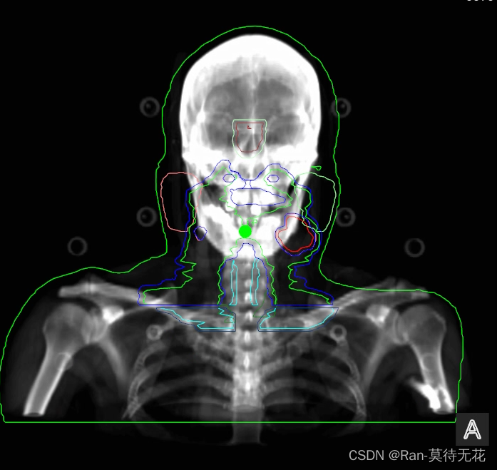
如果需要把结构集数据展示在DRR图像上,只需要用[0,1,0]的法向量旋转一定角度,在计算出新的法向量,用新的法向量切面去切ROI的三维模型即可(生成ROI三维模型的方法在RTSTRUCT ROI三维模型)
最终得到的图像如下:


 3097
3097

 被折叠的 条评论
为什么被折叠?
被折叠的 条评论
为什么被折叠?
 到【灌水乐园】发言


