


这篇博客记录下 STM32F103R8T6 是怎么开ADC、用DMA搬数据的方法。方便日后使用的时候查资料。
DMA其实就是个搬运工,专门负责搬数据,没有DMA之前,搬数据是由MCU核心来负责,虽说都能完成搬数据的动作,但是MCU干这件事浪费资源且效率低,所以有DMA的场合尽量使用DMA来负责搬数据,需要读数据的时候,可以直接去数组里取就行了。
从建工程开始,下面是各步骤:
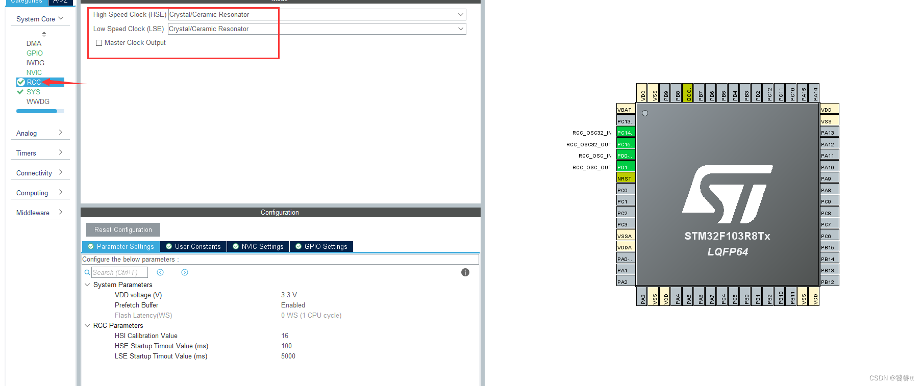
第一步–选择时钟输入:
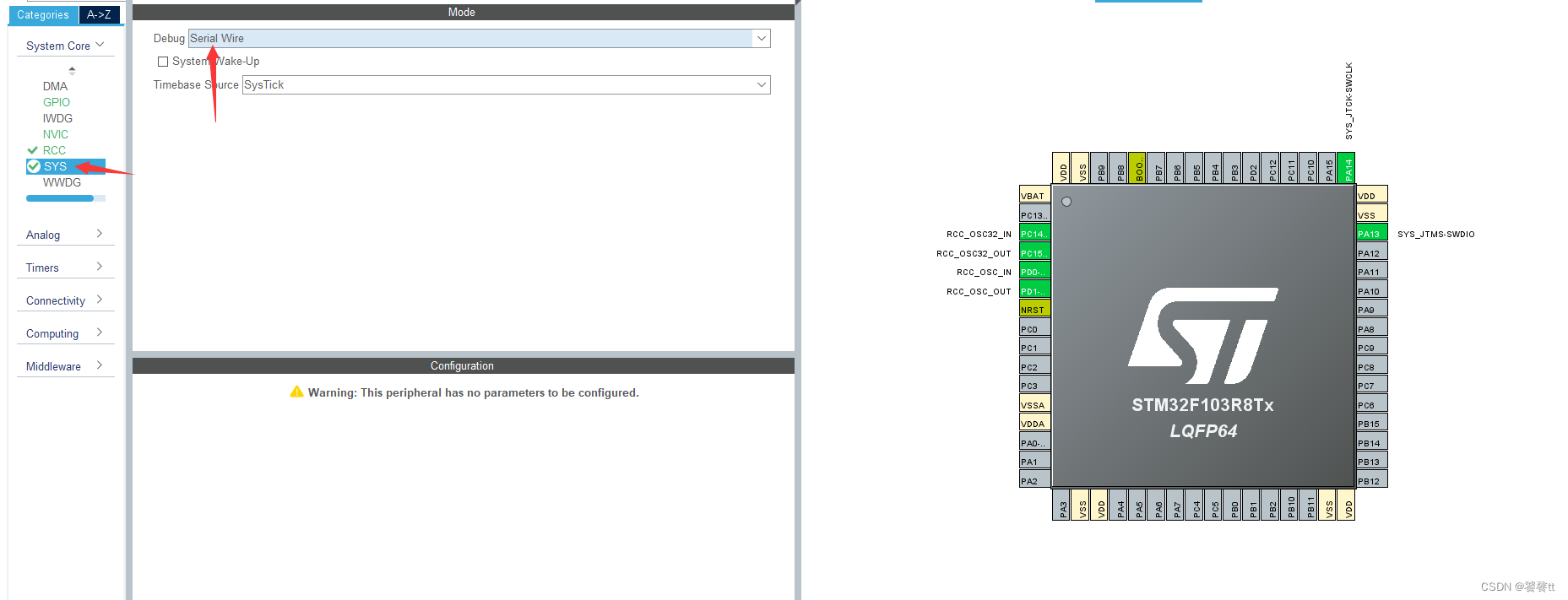
第二步–设置调试模式:
第三步–设置ADC基础设置、打开DMA
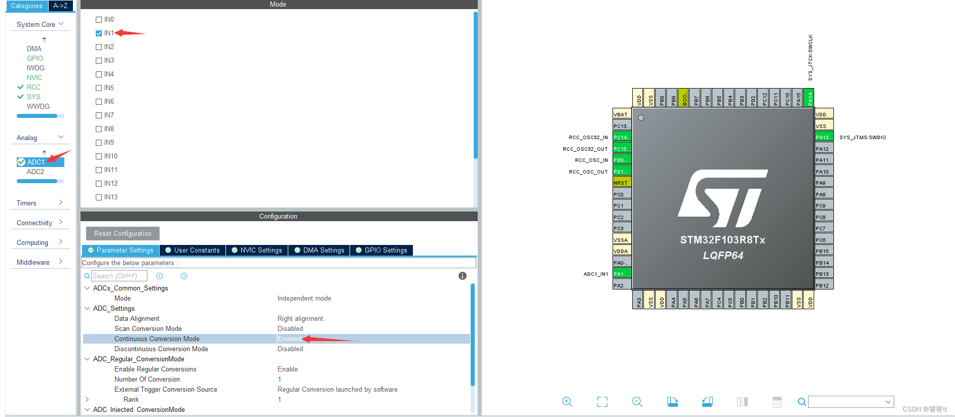
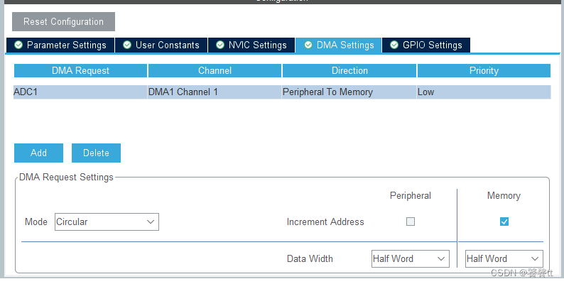
DMA模式选择为circular,代表循环模式,读完一次ADC之后,DMA继续读,并且继续往存放结果值的数组里面搬数据。
开启了DMA之后,32CubeMx默认帮我们开启了ADC的DMA中断,就是读取到满足条件的值之后,会产生一个中断。比如我们设置了DMA读10次数值,然后中断一次,那么DMA在搬了10次数据之后就会产生一个中断,我们需要到回调函数里面做相应的处理。这个中断是可以关掉的。
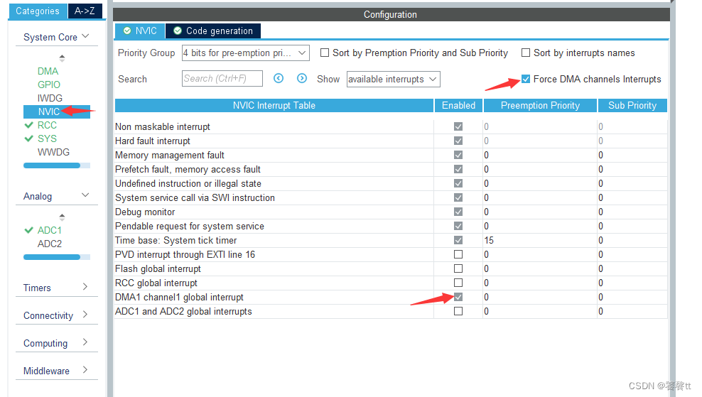
force DMA channels interrupts 这个对勾取消掉,就可以把下面灰色的对勾取消。这样设置后,读取10次(假设我们设置了DMA读10次)值之后,也不会进入中断。
第四步–设置芯片主频
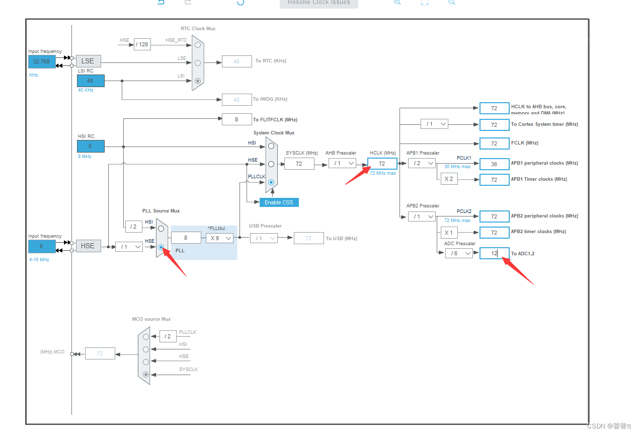
我选的是外部晶振,使用的是8Mhz频率的,倍频之后最大可以设置为72Mhz,那么这里就把主频开到最大,但是ADC的频率是不能太大的,32CubeMx会做一个限制,最多也就能选到12。ADC最快的时钟前面看其他博客有看到,但是现在没找到,先留个坑在这,以后知道多少了再来填。
完成了上面的设置后,基本就OK了,最后一步设置一下生成的项目文件
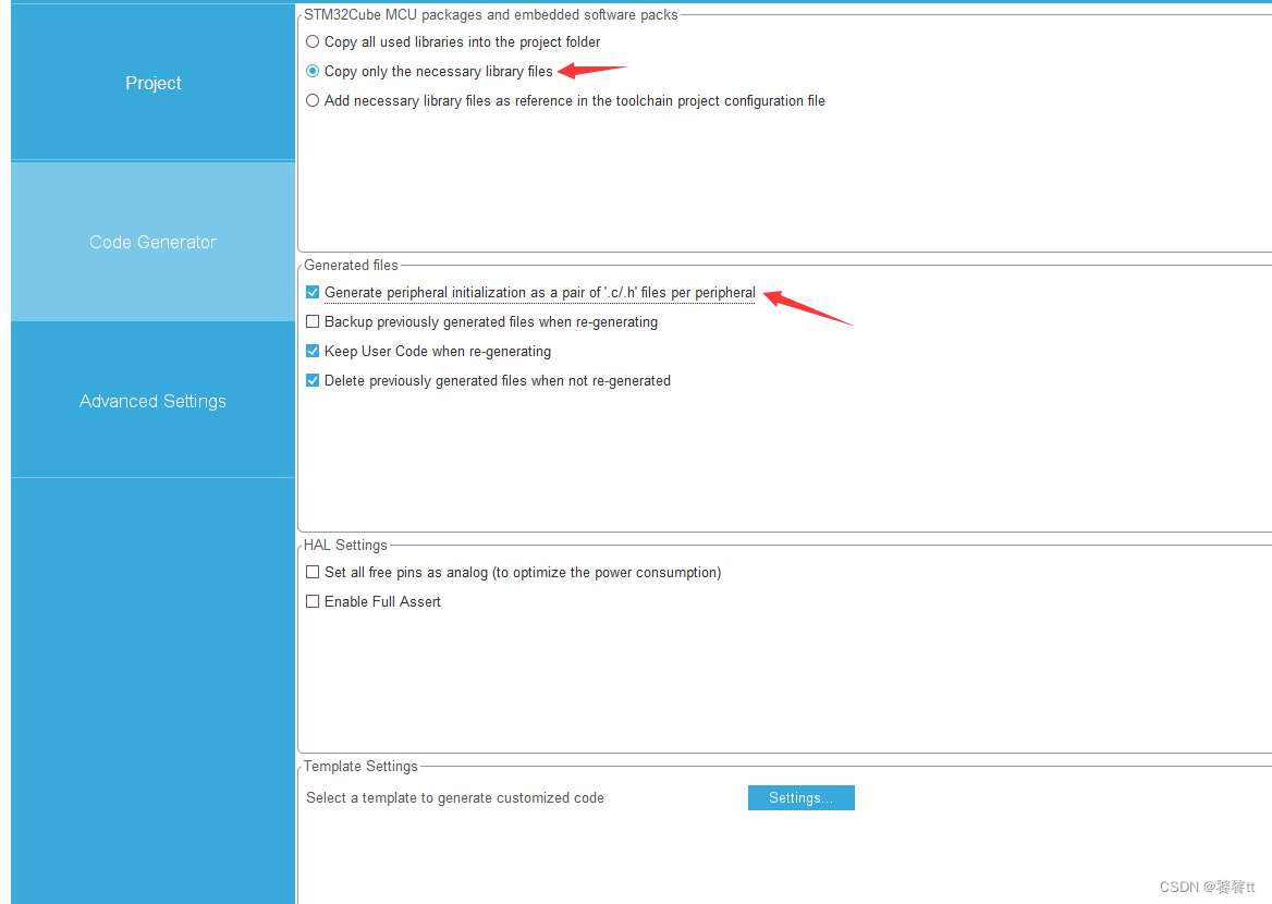
选择只包含使用到的头文件进来。
选择为外设初始化单独的.c和.h文件。
给项目命好名,然后选择生成MDK文件。生成项目,并打开项目。
主函数里面添加这几句调用函数,把ADC功能开起来
/* USER CODE BEGIN Header */
/**
  ******************************************************************************
  * @file           : main.c
  * @brief          : Main program body
  ******************************************************************************
  * @attention
  *
  * Copyright (c) 2022 STMicroelectronics.
  * All rights reserved.
  *
  * This software is licensed under terms that can be found in the LICENSE file
  * in the root directory of this software component.
  * If no LICENSE file comes with this software, it is provided AS-IS.
  *
  ******************************************************************************
  */
/* USER CODE END Header */
/* Includes ------------------------------------------------------------------*/
#include "main.h"
#include "adc.h"
#include "dma.h"
#include "gpio.h"

/* Private includes ----------------------------------------------------------*/
/* USER CODE BEGIN Includes */
typedef   unsigned char   u8;
typedef   unsigned int    u16;
/* USER CODE END Includes */

/* Private typedef -----------------------------------------------------------*/
/* USER CODE BEGIN PTD */

/* USER CODE END PTD */

/* Private define ------------------------------------------------------------*/
/* USER CODE BEGIN PD */
/* USER CODE END PD */

/* Private macro -------------------------------------------------------------*/
/* USER CODE BEGIN PM */

/* USER CODE END PM */

/* Private variables ---------------------------------------------------------*/

/* USER CODE BEGIN PV */
	float volt=0;
	u16   temp=0;
	u8 		i;
	uint16_t adcbuf[15]={0};
/* USER CODE END PV */

/* Private function prototypes -----------------------------------------------*/
void SystemClock_Config(void);
/* USER CODE BEGIN PFP */

/* USER CODE END PFP */

/* Private user code ---------------------------------------------------------*/
/* USER CODE BEGIN 0 */

/* USER CODE END 0 */

/**
  * @brief  The application entry point.
  * @retval int
  */
int main(void)
{
  /* USER CODE BEGIN 1 */

  /* USER CODE END 1 */

  /* MCU Configuration--------------------------------------------------------*/

  /* Reset of all peripherals, Initializes the Flash interface and the Systick. */
  HAL_Init();

  /* USER CODE BEGIN Init */

  /* USER CODE END Init */

  /* Configure the system clock */
  SystemClock_Config();

  /* USER CODE BEGIN SysInit */

  /* USER CODE END SysInit */

  /* Initialize all configured peripherals */
  MX_GPIO_Init();
  MX_DMA_Init();
  MX_ADC1_Init();										//里面已经选择好了相应的通道
  /* USER CODE BEGIN 2 */
	HAL_ADCEx_Calibration_Start(&hadc1);				//开启ADC1
	HAL_ADC_Start_DMA(&hadc1,(uint32_t *)adcbuf,10);	//开启负责ADC1的DMA通道,把存放结果的数组首地址传过来,搬运10次产生/不产生中断
  /* USER CODE END 2 */

  /* Infinite loop */
  /* USER CODE BEGIN WHILE */
  while (1)
  {
    /* USER CODE END WHILE */
	HAL_Delay(50);
    for(i=0;i<10;i++)
    {
        temp += adcbuf[i];
    }
    temp = temp/10;					//累加10次的结果 做平均处理
    volt = (float)temp/4096*3.24;	//处理过后的值 计算输入电压是多少
    temp = 0;
    /* USER CODE BEGIN 3 */
  }
  /* USER CODE END 3 */
}

/**
  * @brief System Clock Configuration
  * @retval None
  */
void SystemClock_Config(void)
{
  RCC_OscInitTypeDef RCC_OscInitStruct = {0};
  RCC_ClkInitTypeDef RCC_ClkInitStruct = {0};
  RCC_PeriphCLKInitTypeDef PeriphClkInit = {0};

  /** Initializes the RCC Oscillators according to the specified parameters
  * in the RCC_OscInitTypeDef structure.
  */
  RCC_OscInitStruct.OscillatorType = RCC_OSCILLATORTYPE_HSE;
  RCC_OscInitStruct.HSEState = RCC_HSE_ON;
  RCC_OscInitStruct.HSEPredivValue = RCC_HSE_PREDIV_DIV1;
  RCC_OscInitStruct.HSIState = RCC_HSI_ON;
  RCC_OscInitStruct.PLL.PLLState = RCC_PLL_ON;
  RCC_OscInitStruct.PLL.PLLSource = RCC_PLLSOURCE_HSE;
  RCC_OscInitStruct.PLL.PLLMUL = RCC_PLL_MUL9;
  if (HAL_RCC_OscConfig(&RCC_OscInitStruct) != HAL_OK)
  {
    Error_Handler();
  }

  /** Initializes the CPU, AHB and APB buses clocks
  */
  RCC_ClkInitStruct.ClockType = RCC_CLOCKTYPE_HCLK|RCC_CLOCKTYPE_SYSCLK
                              |RCC_CLOCKTYPE_PCLK1|RCC_CLOCKTYPE_PCLK2;
  RCC_ClkInitStruct.SYSCLKSource = RCC_SYSCLKSOURCE_PLLCLK;
  RCC_ClkInitStruct.AHBCLKDivider = RCC_SYSCLK_DIV1;
  RCC_ClkInitStruct.APB1CLKDivider = RCC_HCLK_DIV2;
  RCC_ClkInitStruct.APB2CLKDivider = RCC_HCLK_DIV1;

  if (HAL_RCC_ClockConfig(&RCC_ClkInitStruct, FLASH_LATENCY_2) != HAL_OK)
  {
    Error_Handler();
  }
  PeriphClkInit.PeriphClockSelection = RCC_PERIPHCLK_ADC;
  PeriphClkInit.AdcClockSelection = RCC_ADCPCLK2_DIV6;
  if (HAL_RCCEx_PeriphCLKConfig(&PeriphClkInit) != HAL_OK)
  {
    Error_Handler();
  }
}

/* USER CODE BEGIN 4 */

/* USER CODE END 4 */

/**
  * @brief  This function is executed in case of error occurrence.
  * @retval None
  */
void Error_Handler(void)
{
  /* USER CODE BEGIN Error_Handler_Debug */
  /* User can add his own implementation to report the HAL error return state */
  __disable_irq();
  while (1)
  {
  }
  /* USER CODE END Error_Handler_Debug */
}

#ifdef  USE_FULL_ASSERT
/**
  * @brief  Reports the name of the source file and the source line number
  *         where the assert_param error has occurred.
  * @param  file: pointer to the source file name
  * @param  line: assert_param error line source number
  * @retval None
  */
void assert_failed(uint8_t *file, uint32_t line)
{
  /* USER CODE BEGIN 6 */
  /* User can add his own implementation to report the file name and line number,
     ex: printf("Wrong parameters value: file %s on line %d\r\n", file, line) */
  /* USER CODE END 6 */
}
#endif /* USE_FULL_ASSERT */
输入值跟计算出来的理论值:本个项目是输入2.692V,通过理论计算出来的volt=2.68多,差了0.01V不到。
这次是使用了比较简单的ADC功能,还有很多高级功能,比如注入转换这类的高级功能还没时间细细研究。先跳过其他复杂功能继续往下学习。


 3万+
3万+


 被折叠的 条评论
为什么被折叠?
被折叠的 条评论
为什么被折叠?
 到【灌水乐园】发言


