


 文章介绍了ModelSim作为QuartusPrime的仿真工具,用于验证数字电路设计的功能和时序。内容包括ModelSim的工作原理、主要功能,如单步执行、波形查看和调试。文章还提供了一个简单的使用教程,涵盖新建工程、生成仿真文件、设置仿真、功能仿真及时序仿真的步骤。
quartus工具篇——modelsim的使用
1、modelsim简介
Quartus Prime是一款由英特尔开发的集成电路设计软件,而ModelSim是Quartus的一个可选工具,用于进行数字电路仿真和验证。下面是对ModelSim在Quartus中的一些简要介绍:
- 工作原理:ModelSim是一款基于事件驱动的数字仿真器,使用硬件描述语言(如VHDL或Verilog)来描述和模拟电路行为。它可以帮助设计人员验证他们的电路设计在真实硬件上的功能和时序。
- 仿真功能:ModelSim提供了丰富的仿真功能,包括单步执行、断点设置、波形查看、变量监视等。您可以在仿真环境中模拟和观察电路的行为,以确保其在各种情况下都能正确运行。
- 波形编辑器:ModelSim配备了强大的波形编辑器,可以用于查看和分析仿真波形。您可以对信号值、时间、层次结构等进行详细设置和调整,以便更好地理解电路的工作方式。
- 调试功能:ModelSim还提供了强大的调试功能,可用于定位和修复电路设计中的问题。您可以设置断点、监视变量、跟踪信号路径等,以辅助调试过程。
- 与Quartus集成:Quartus提供了与ModelSim的紧密集成,使您可以在Quartus环境中直接启动ModelSim仿真。这种无缝集成简化了设计流程,并使您能够快速切换设计和仿真环境。
需要注意的是,ModelSim作为Quartus的可选工具,通常需要单独安装,并且可能会需要额外的许可证。因此,在使用ModelSim之前,您需要检查您的Quartus版本以及相关许可证要求。
二、使用教程
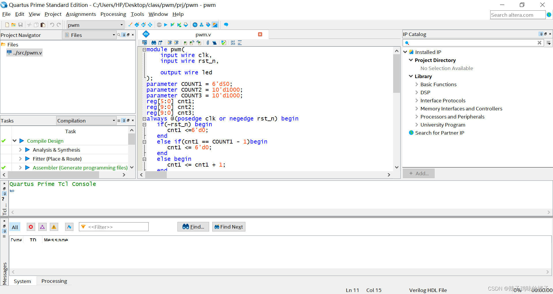
1、新建工程添加文件
这里操作很简单,这里就不再赘述,结果如下图:
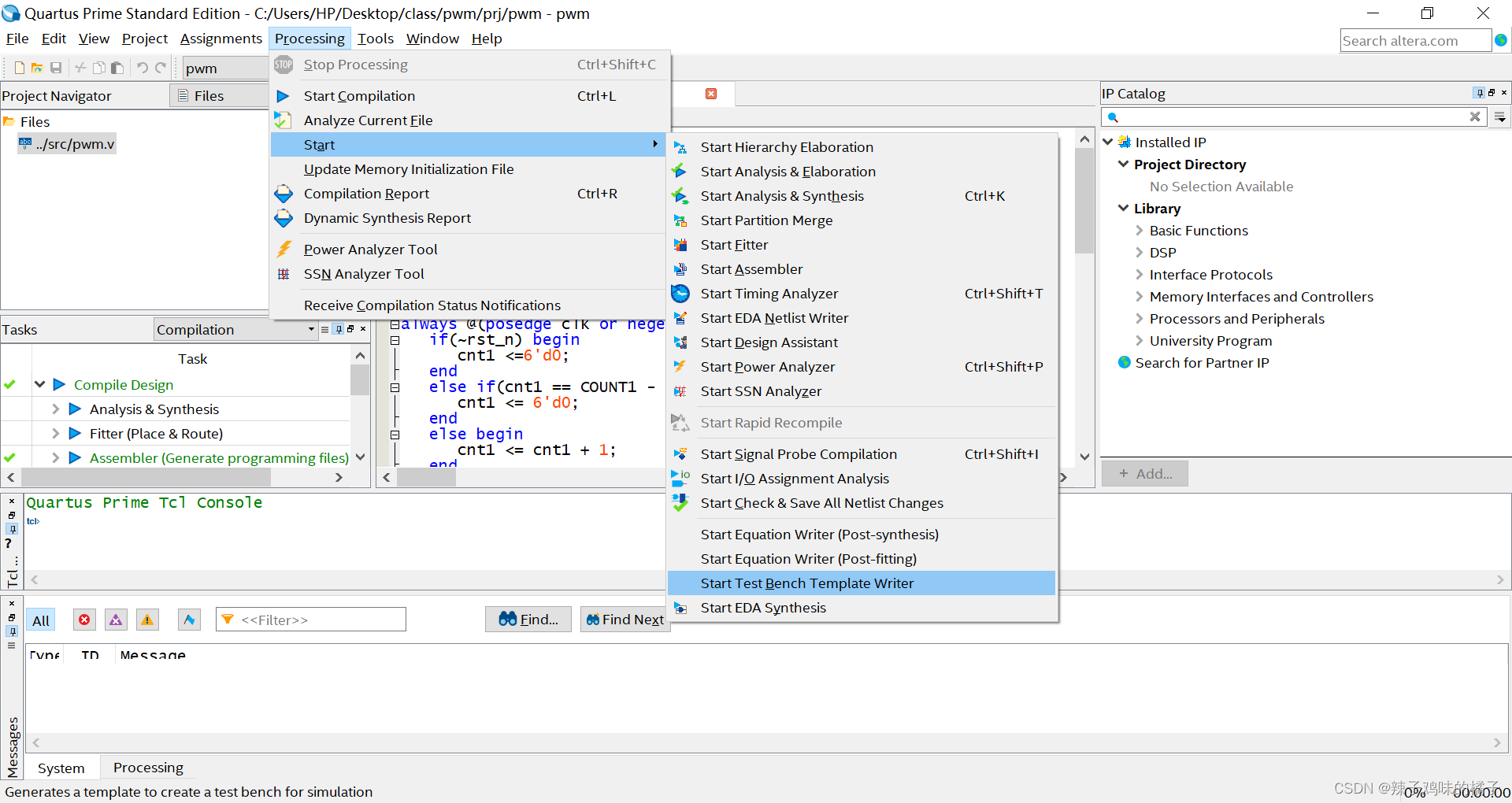
2、生成编写仿真文件
生成仿真文件
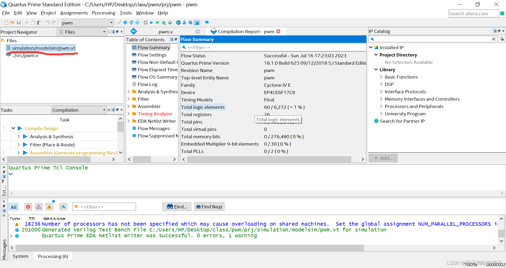
生成的文件会在你创建工程的目录下,如图:
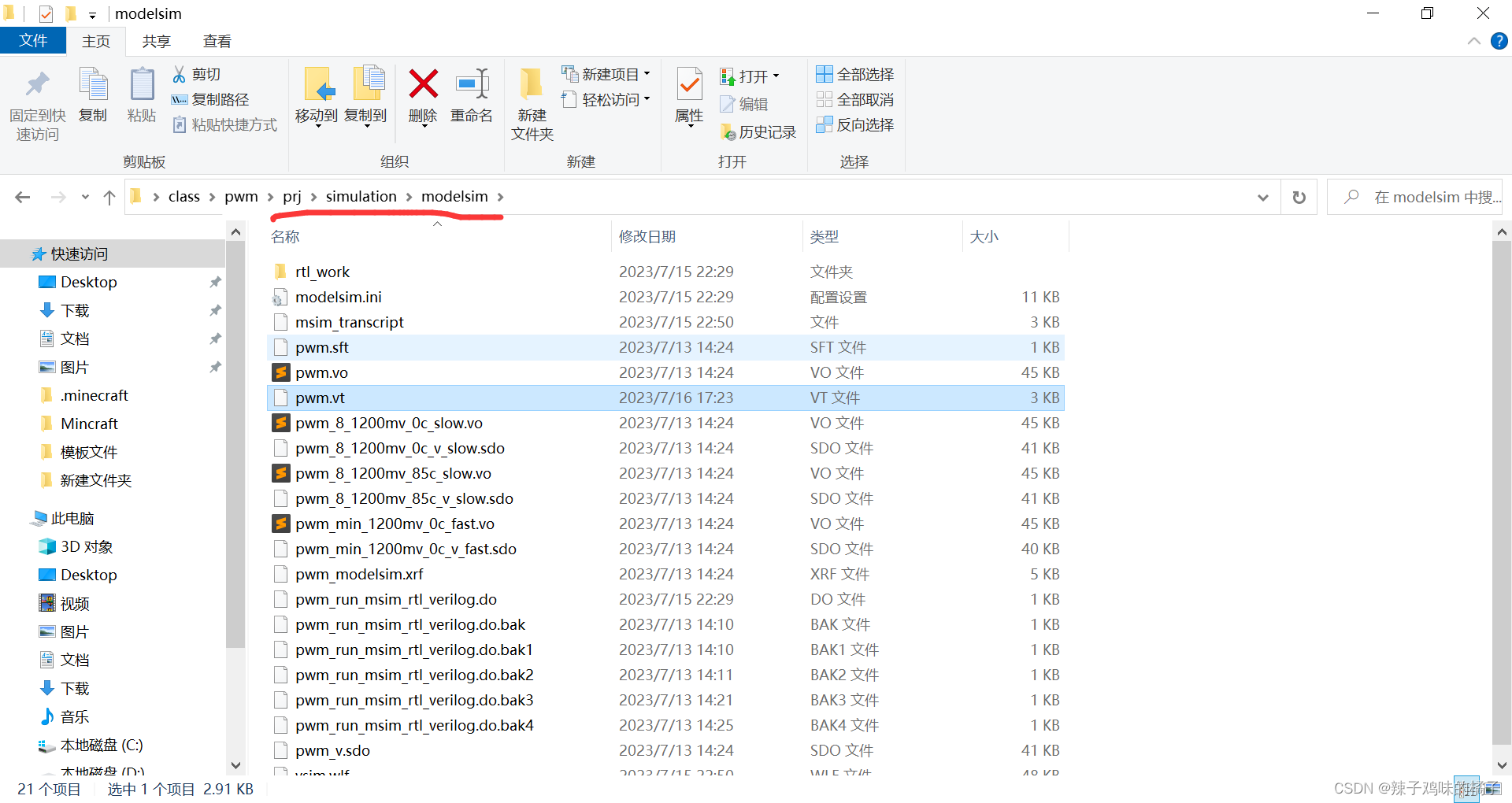
我这里是工程是创建在prj下,所以文件会生成在simulation->modelsim文件夹下,将.vt的文件添加进工程
重写.vt文件,可以将里面的内容替换成你自己编写的仿真文件的内容,一般是修改initial后的内容,
修改前:
// Copyright (C) 2018  Intel Corporation. All rights reserved.
// Your use of Intel Corporation's design tools, logic functions
// and other software and tools, and its AMPP partner logic
// functions, and any output files from any of the foregoing
// (including device programming or simulation files), and any
// associated documentation or information are expressly subject
// to the terms and conditions of the Intel Program License
// Subscription Agreement, the Intel Quartus Prime License Agreement,
// the Intel FPGA IP License Agreement, or other applicable license
// agreement, including, without limitation, that your use is for
// the sole purpose of programming logic devices manufactured by
// Intel and sold by Intel or its authorized distributors.  Please
// refer to the applicable agreement for further details.

// *****************************************************************************
// This file contains a Verilog test bench template that is freely editable to
// suit user's needs .Comments are provided in each section to help the user
// fill out necessary details.
// *****************************************************************************
// Generated on "07/16/2023 17:23:03"

// Verilog Test Bench template for design : pwm
//
// Simulation tool : ModelSim-Altera (Verilog)
//

`timescale 1 ps/ 1 ps
module pwm_vlg_tst();
// constants
// general purpose registers
reg eachvec;
// test vector input registers
reg clk;
reg rst_n;
// wires
wire led;

// assign statements (if any)
pwm i1 (
// port map - connection between master ports and signals/registers
	.clk(clk),
	.led(led),
	.rst_n(rst_n)
);
initial
begin
// code that executes only once
// insert code here --> begin

// --> end
$display("Running testbench");
end
always
// optional sensitivity list
// @(event1 or event2 or .... eventn)
begin
// code executes for every event on sensitivity list
// insert code here --> begin

@eachvec;
// --> end
end
endmodule
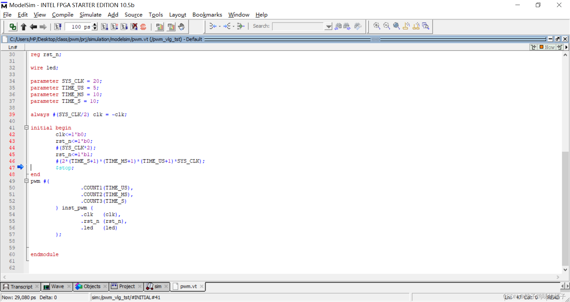
修改后:
// Copyright (C) 2018  Intel Corporation. All rights reserved.
// Your use of Intel Corporation's design tools, logic functions
// and other software and tools, and its AMPP partner logic
// functions, and any output files from any of the foregoing
// (including device programming or simulation files), and any
// associated documentation or information are expressly subject
// to the terms and conditions of the Intel Program License
// Subscription Agreement, the Intel Quartus Prime License Agreement,
// the Intel FPGA IP License Agreement, or other applicable license
// agreement, including, without limitation, that your use is for
// the sole purpose of programming logic devices manufactured by
// Intel and sold by Intel or its authorized distributors.  Please
// refer to the applicable agreement for further details.

// *****************************************************************************
// This file contains a Verilog test bench template that is freely editable to
// suit user's needs .Comments are provided in each section to help the user
// fill out necessary details.
// *****************************************************************************
// Generated on "07/16/2023 17:23:03"

// Verilog Test Bench template for design : pwm
//
// Simulation tool : ModelSim-Altera (Verilog)
//

`timescale 1 ps/ 1 ps
module pwm_vlg_tst();
reg clk;
reg rst_n;

wire led;

parameter SYS_CLK = 20;
parameter TIME_US = 5;
parameter TIME_MS = 10;
parameter TIME_S = 10;

always #(SYS_CLK/2) clk = ~clk;

initial begin
	clk<=1'b0;
	rst_n<=1'b0;
	#(SYS_CLK*2);
	rst_n<=1'b1;
	#(2*(TIME_S+1)*(TIME_MS+1)*(TIME_US+1)*SYS_CLK);
	$stop;
end
pwm #(
		.COUNT1(TIME_US),
		.COUNT2(TIME_MS),
		.COUNT3(TIME_S)
	) inst_pwm (
		.clk   (clk),
		.rst_n (rst_n),
		.led   (led)
	);
endmodule
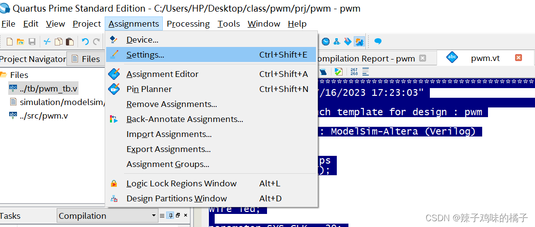
3、设置仿真
打开simuation选项:
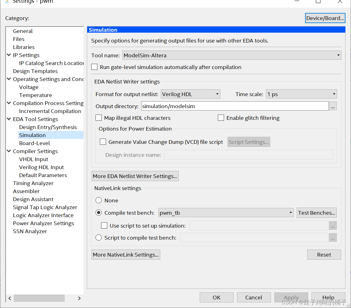
添加.vt文件
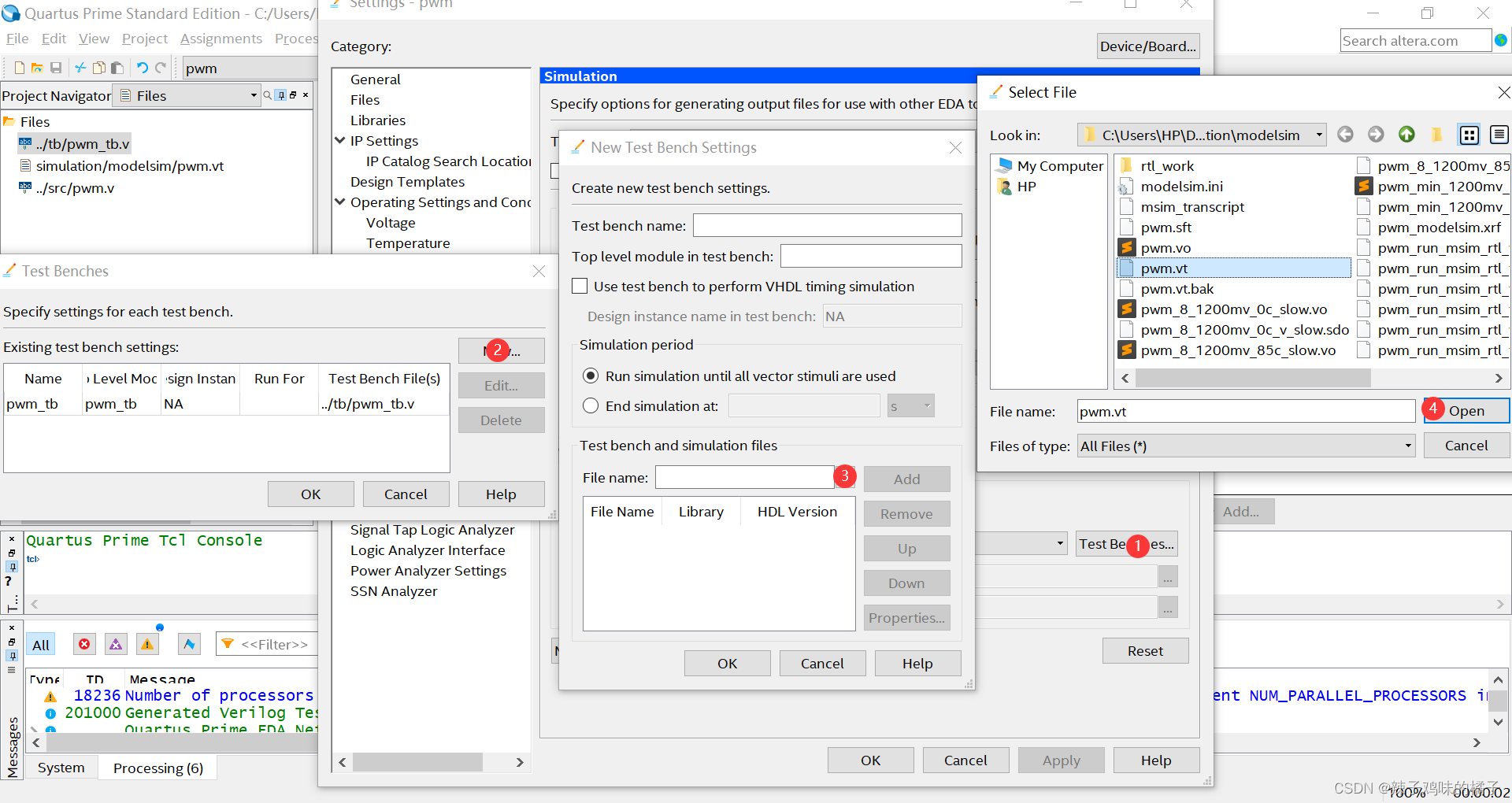
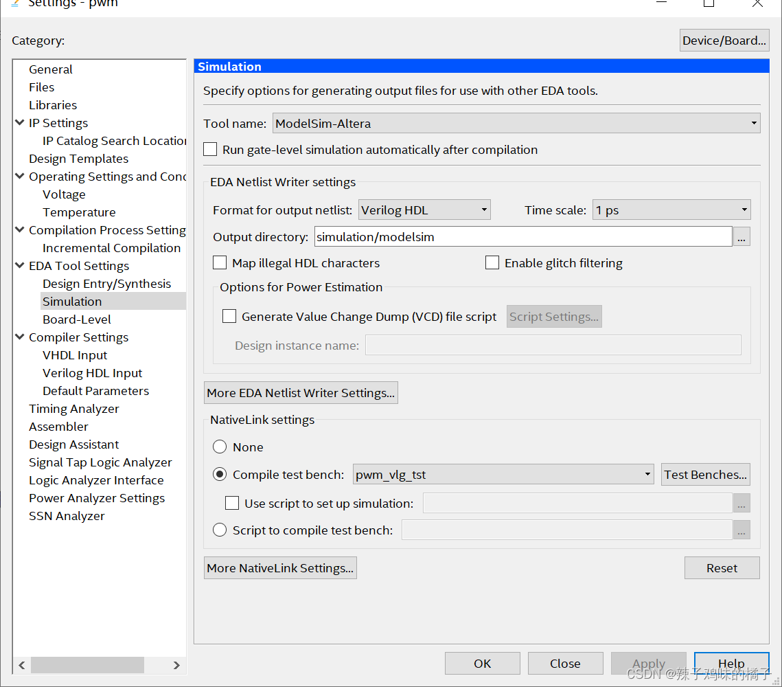
testbench填入仿真文件中的模块名
![[外链图片转存失败,源站可能有防盗链机制,建议将图片保存下来直接上传(img-a3CSTLKZ-1689500876759)(C:/Users/HP/AppData/Roaming/Typora/typora-user-images/image-20230716173546161.png)]](https://i-blog.csdnimg.cn/blog_migrate/cf605c17279b21ba32e9901f8ac9f258.png)
点击add添加即可,结果如下图
4、开启功能仿真
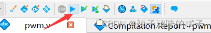
编译文件:
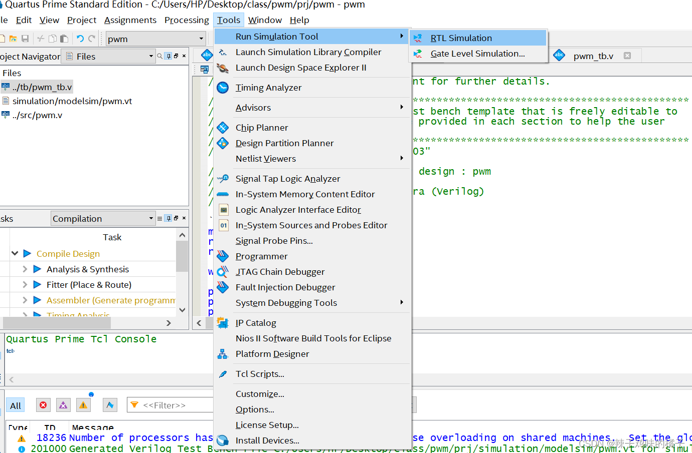
开启仿真:
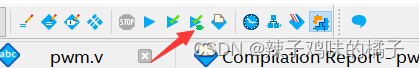
运行后会打开modelsim
点击wave查看仿真
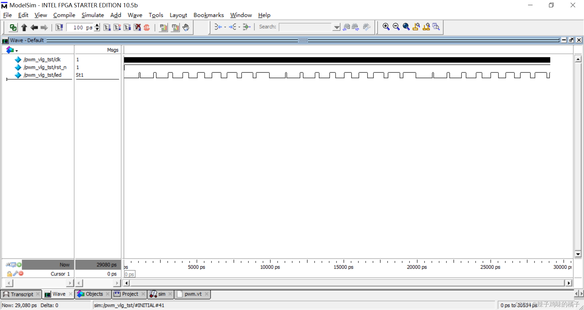
具体的modelsim操作这里就不进行细讲了
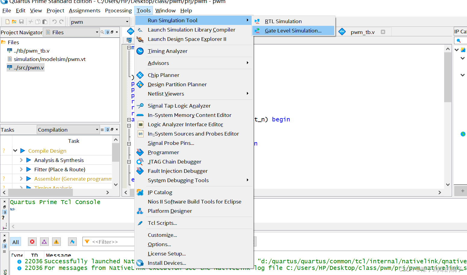
5、开启时序仿真
时序仿真需要运行项目
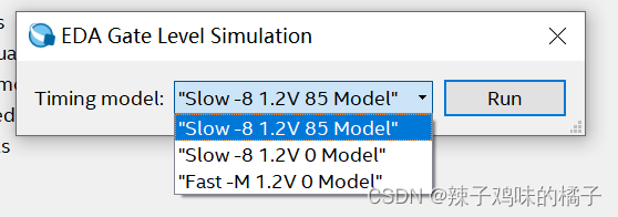
开启时序仿真
点击默认的,点击run开始运行
结果:

与功能仿真不同的是,时序仿真有延时,不能像功能仿真理想化
6、总结
modelsim在quartus中的操作相对简单,当然也可以直接在modelsim中进行操作,相对来说很复杂,得出的效果也是一样的。


 3309
3309

 被折叠的 条评论
为什么被折叠?
被折叠的 条评论
为什么被折叠?
 到【灌水乐园】发言


