课程设计:十字路口红绿灯控制器
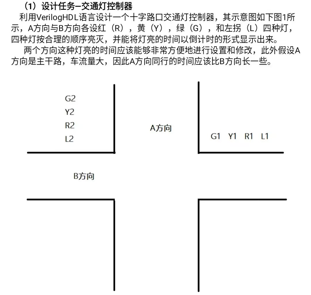
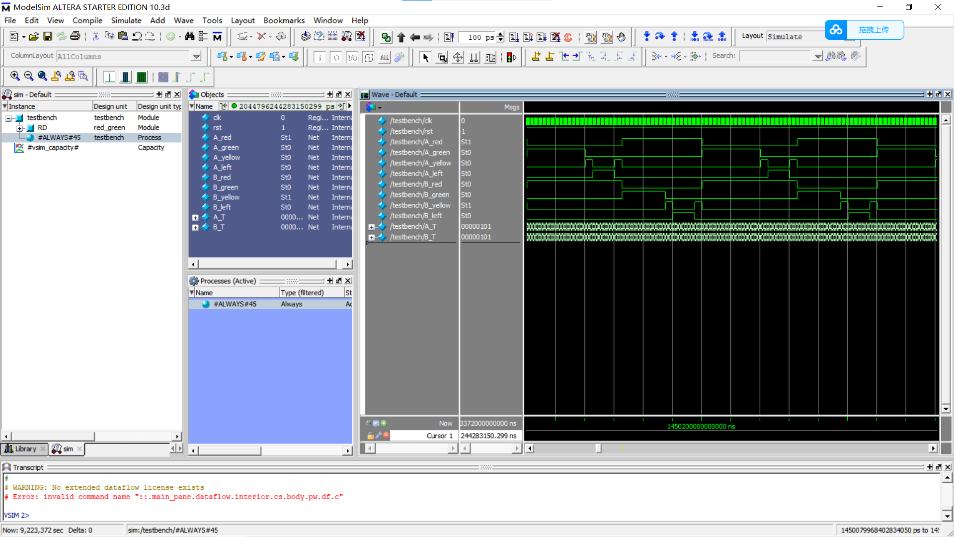
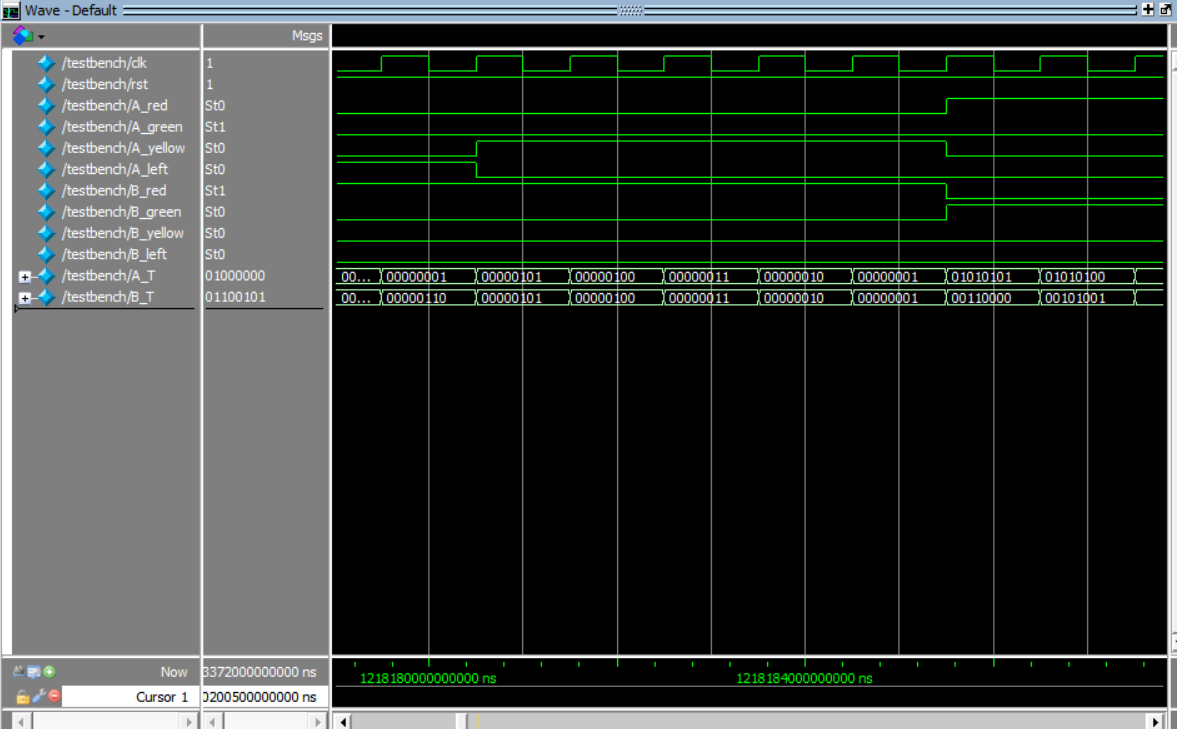
1.要求双方向8个灯的时序控制
2.要求显示倒计时

verilog hdl代码模块
module red_green(
     input clk, //系统时钟
     input rst,

     output reg A_red,
     output reg A_green,
     output reg A_yellow,
     output reg A_left,

     output reg B_red,
     output reg B_green,
     output reg B_yellow,
     output reg B_left,

     output reg[7:0] A_T,
     output reg[7:0] B_T
);
//灯的显示时间,系统分配32位宽
parameter A_yellow_time = 5;
parameter A_left_time = 15;
parameter A_red_time = 55;
parameter A_green_time = 40;

parameter B_yellow_time = 5;
parameter B_left_time = 15;
parameter B_red_time = 65;
parameter B_green_time = 30;

reg [2:0] A_state;
reg [2:0] B_state;
reg [7:0] A_count;
reg [7:0] B_count;
//A灯的状态
always @(posedge clk or negedge rst)

case(A_state)
    0:                 //A绿灯
        begin
        A_green <= 1'b1;
        A_yellow <= 1'b0;
        A_left <= 1'b0;
        A_red <=1'b0;
        end
    1:                 //A黄灯
        begin
        A_green <= 1'b0;
        A_yellow <= 1'b1;
        A_left <= 1'b0;
        A_red <=1'b0;
        end
    2:                 //A左转灯
        begin
        A_green <= 1'b0;
        A_yellow <= 1'b0;
        A_left <= 1'b1;
        A_red <=1'b0;
        end
    3:                 //A黄灯
        begin
        A_green <= 1'b0;
        A_yellow <= 1'b1;
        A_left <= 1'b0;
        A_red <=1'b0;
        end
default:              //A红灯
        begin
        A_green <= 1'b0;
        A_yellow <= 1'b0;
        A_left <= 1'b0;
        A_red <=1'b1;
        end
endcase

//A灯的计时以及状态变化
always @(posedge clk or negedge rst)
begin
if(rst==0)
begin
A_count<=A_green_time;
A_state<=0;
end
else
    begin
        if(A_count==1)   //计时到1时变换
            begin
                if(A_state==4)
                begin
                    A_state <=0;  //状态到最后一个时,A状态回到0循环
                    A_count <=A_green_time;
                end
                else
                    A_state <= A_state+1; //否则,下一个状态
                    case(A_state)
                    0: A_count <= A_yellow_time;
                    1: A_count <= A_left_time;
                    2: A_count <= A_yellow_time;
                    3: A_count <= A_red_time;
            default: A_count <= A_green_time;    //给下一个状态赋予时间
                    endcase
            end
        else A_count<=A_count-1;
    end
end


//B灯的状态
always @(posedge clk or negedge rst)

case(B_state)
    0:                 //B红灯
        begin
        B_green <= 1'b0;
        B_yellow <= 1'b0;
        B_left <= 1'b0;
        B_red <=1'b1;
        end
    1:                 //B绿灯
        begin
        B_green <= 1'b1;
        B_yellow <= 1'b0;
        B_left <= 1'b0;
        B_red <=1'b0;
        end
    2:                 //B黄灯
        begin
        B_green <= 1'b0;
        B_yellow <= 1'b1;
        B_left <= 1'b0;
        B_red <=1'b0;
        end
    3:                 //B左转灯
        begin
        B_green <= 1'b0;
        B_yellow <= 1'b0;
        B_left <= 1'b1;
        B_red <=1'b0;
        end
default:              //B黄灯
        begin
        B_green <= 1'b0;
        B_yellow <= 1'b1;
        B_left <= 1'b0;
        B_red <=1'b0;
        end
endcase
//B灯的计时以及状态变化
always @(posedge clk or negedge rst)
begin
if (rst==0)
begin
    B_count<=B_red_time;
    B_state<=0;
end
else
    begin
        if(B_count==1)   //计时到1时变换
            begin
                if(B_state==4)
                begin
                    B_state <=0;  //状态到最后一个时,B状态回到0循环
                    B_count <=B_red_time;
                end
                else
                    B_state <= B_state+1; //否则,下一个状态
                    case(B_state)
                    0: B_count <= B_green_time;
                    1: B_count <= B_yellow_time;
                    2: B_count <= B_left_time;
                    3: B_count <= B_yellow_time;
            default: B_count <= B_red_time;    //给下一个状态赋予时间
                    endcase
            end
        else B_count<=B_count-1;
    end
end


//移位加3法,二进制向BCD码的转换
reg [3:0] num_1; //bcd码的十位
reg [3:0] num_0; //bcd码的个位
integer i;
always @(posedge clk)
begin
    num_1=4'b0;   //bcd码的十位
    num_0=4'b0;   //bcd码的个位
    for (i=7;i>=0;i=i-1)
        begin
            if(num_1>=5)
                num_1=num_1+3;
            if(num_0>=5)
                num_0=num_0+3;    //加3

            num_1=num_1<<1;
            num_1[0]=num_0[3];

            num_0=num_0<<1;
            num_0[0]=A_count[i]; //移位
        end
    A_T={num_1,num_0};

    num_1=4'b0;   //bcd码的十位
    num_0=4'b0;   //bcd码的个位
    for (i=7;i>=0;i=i-1)
        begin
            if(num_1>=5)
                num_1=num_1+3;
            if(num_0>=5)
                num_0=num_0+3;    //加3

            num_1=num_1<<1;
            num_1[0]=num_0[3];

            num_0=num_0<<1;
            num_0[0]=B_count[i]; //移位
        end
    B_T={num_1,num_0};

end

endmodule
测试程序模块
`timescale 1ns/1ps   //时间单位1ns,时间精度1ps

module testbench;
    reg clk;   //系统时钟
    reg rst;   //复位
    wire A_red;
    wire A_green;
    wire A_yellow;
    wire A_left;

    wire B_red;
    wire B_green;
    wire B_yellow;
    wire B_left;

    wire [7:0]A_T;
    wire [7:0]B_T;
    //元件例化为RD,仿真连线
    red_green RD
    (
    .clk(clk),
    .rst(rst),
    .A_red(A_red),
    .A_green(A_green),
    .A_yellow(A_yellow),
    .A_left(A_left),
    .B_red(B_red),
    .B_green(B_green),
    .B_yellow(B_yellow),
    .B_left(B_left),

    .A_T(A_T),
    .B_T(B_T)
    );
//初始先复位一次
initial
    begin
        rst=0;
        #30;
        rst=1;
    end


//设置时钟每500000000个单位翻转一次,这样一个时钟周期为1秒
always
    begin
        clk=0;
        #500000000;
        clk=1;
        #500000000;
    end
endmodule

注意:
选择比较好的器件
测试文件命名为testbench.vt,否则不行。
采用BCD倒计时,经测试时序无错,代码结构清晰。
EDA课设,感谢论坛其他大佬的代码,基于站内其他作者单方向灯代码和二进制转BCD写出。


 该文描述了一个使用VerilogHDL编写的十字路口红绿灯控制器的设计,包括对双方向8个灯的时序控制和倒计时显示。代码中定义了不同的灯状态和显示时间,并实现了状态转换和计时功能。此外,还包含了将二进制时间转换为BCD码进行显示的部分。


 2435
2435

 被折叠的 条评论
为什么被折叠?


