


前言
定时器具有
1.Base
2.PWM
3.IC
4.OC
这四种功能,前面我们以及讲完了Base(按键部分),PWM功能,接下来我们要学习的是定时器的IC(输入捕获)功能。
IC
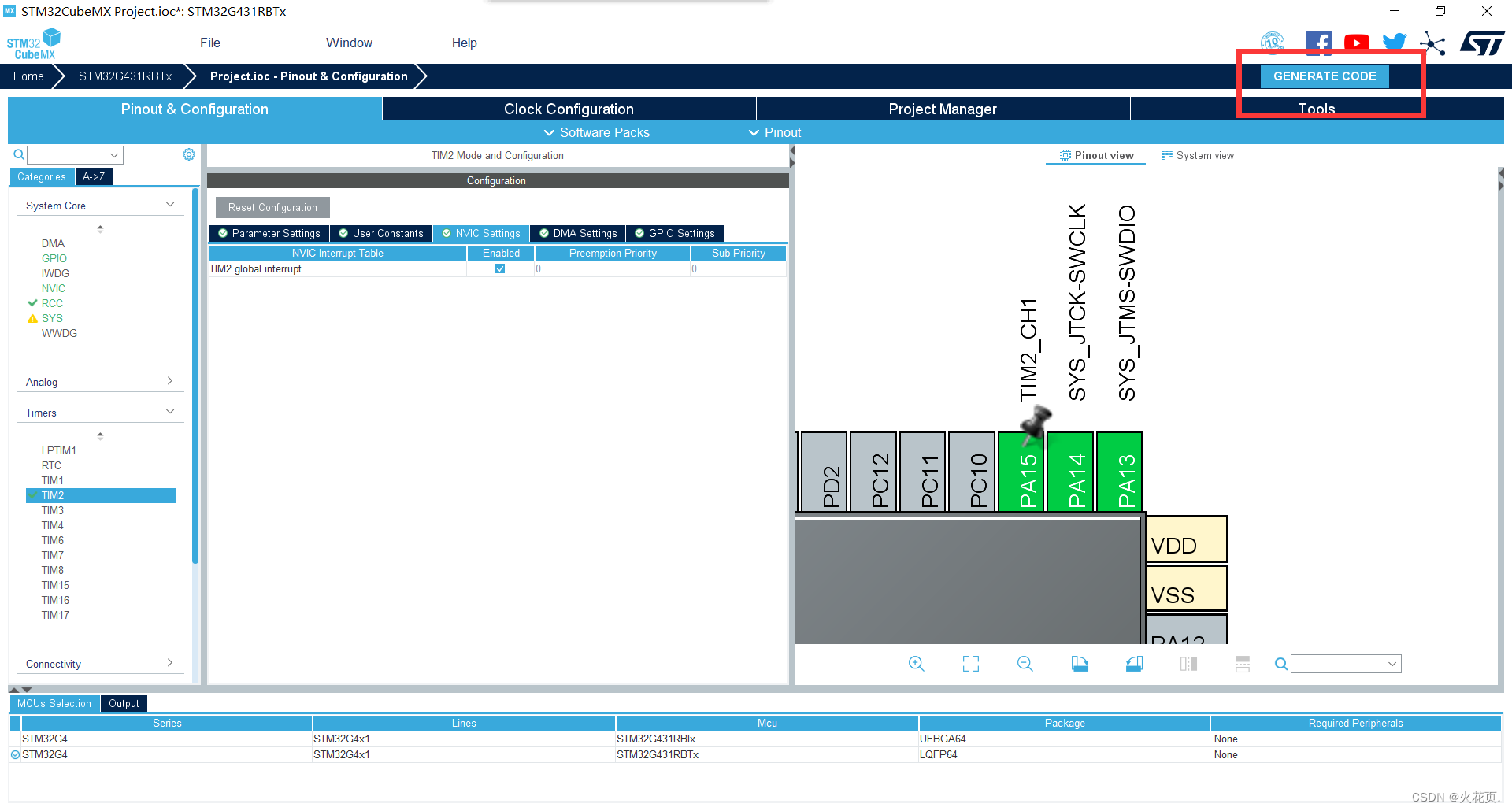
1.原理图以及配置元素
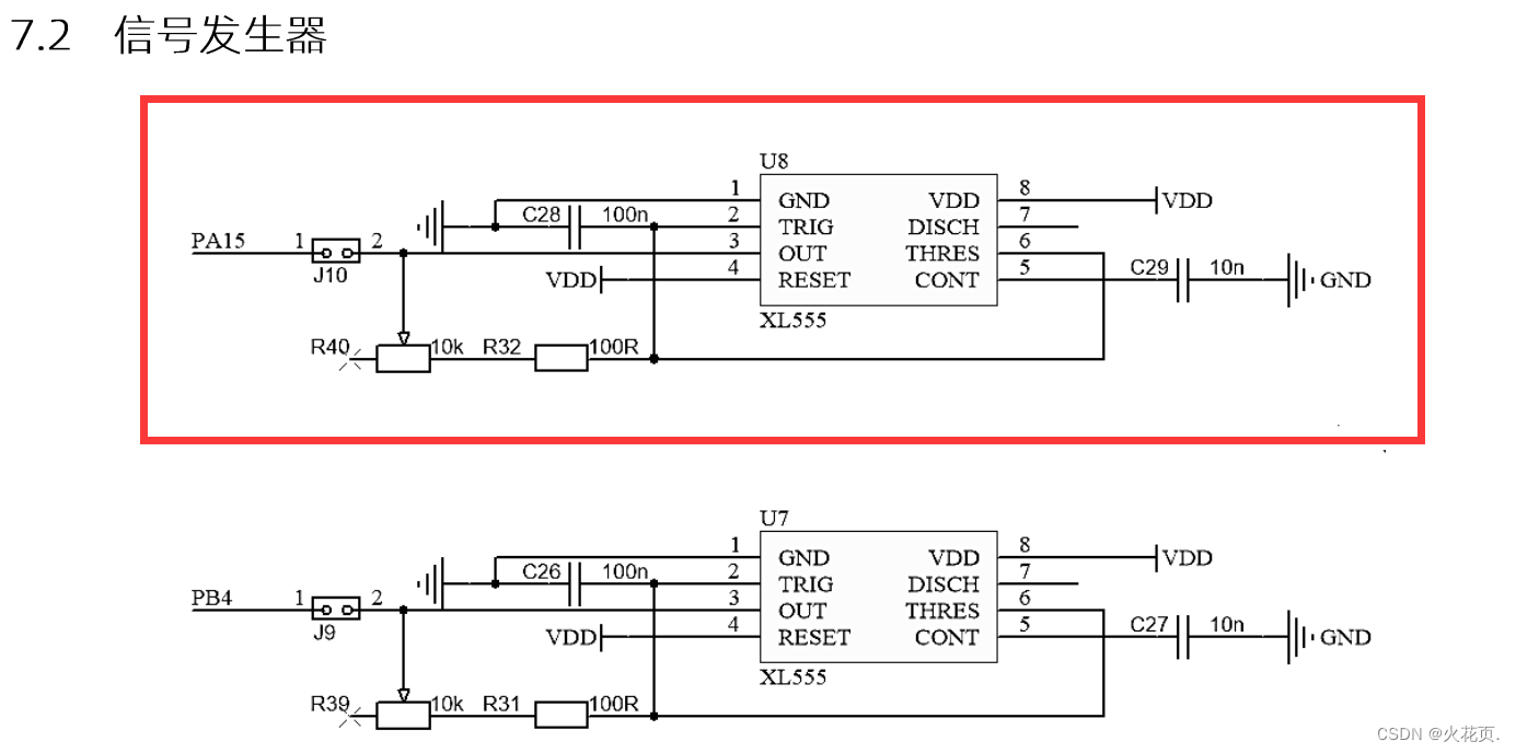
由图可知PA15为输入捕获接口与一个XL555信号发生器连在了一起。
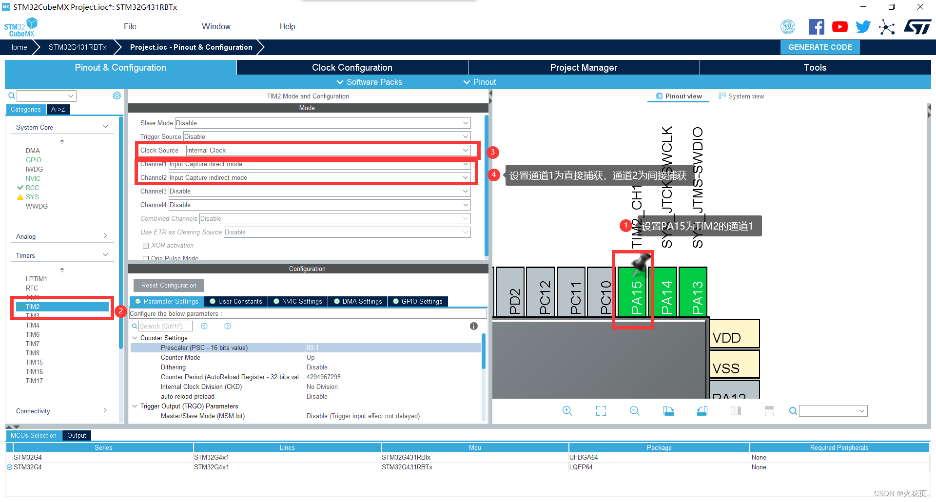
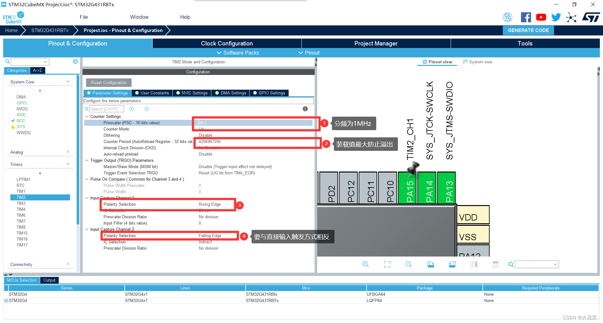
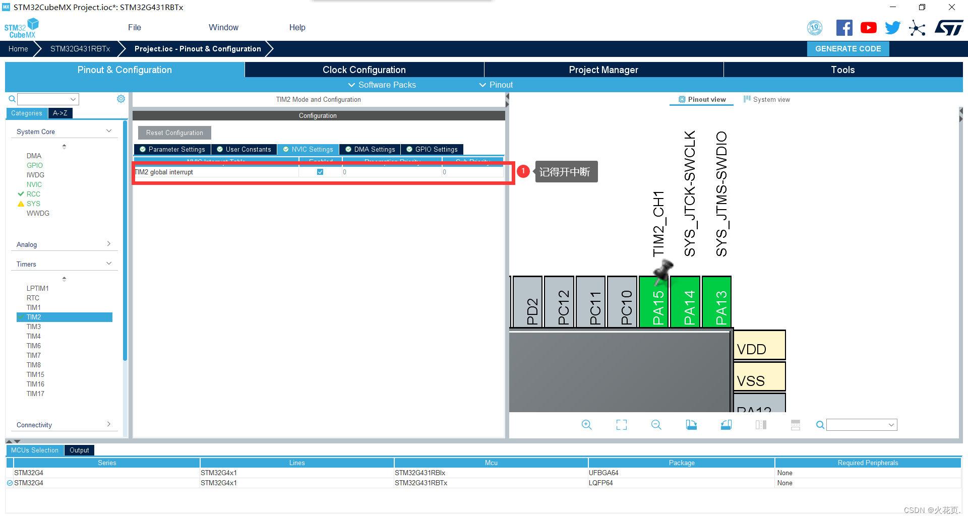
2.CubeMx的配置步骤
3.生成工程
点击GENERATE CODE生成代码后点击Open Project即可。
4.测试代码
interrupt.h
#ifndef __INTERRUPT_H__
#define __INTERRUPT_H__

#include "main.h"

void HAL_TIM_IC_CaptureCallback(TIM_HandleTypeDef *htim);

#endif
interrupt.c
#include "interrupt.h"

unsigned int Period = 0;
unsigned int HighTime = 0;

void HAL_TIM_IC_CaptureCallback(TIM_HandleTypeDef *htim)
{
	if(htim->Instance == TIM2)
	{
		if(htim->Channel == HAL_TIM_ACTIVE_CHANNEL_1)
		{
			Period = HAL_TIM_ReadCapturedValue(htim, TIM_CHANNEL_1); //读取直接通道
			HighTime = HAL_TIM_ReadCapturedValue(htim, TIM_CHANNEL_2); //读取间接通道
			__HAL_TIM_SetCounter(htim, 0);
			HAL_TIM_IC_Start_IT(htim, TIM_CHANNEL_1); //开启中断以便于下次采值
			HAL_TIM_IC_Start_IT(htim, TIM_CHANNEL_2);
		}
	}
}
main.c
/* USER CODE BEGIN Header */
/**
******************************************************************************
* @file : main.c
* @brief : Main program body
******************************************************************************
* @attention
*
* <h2><center>© Copyright (c) 2023 STMicroelectronics.
* All rights reserved.</center></h2>
*
* This software component is licensed by ST under BSD 3-Clause license,
* the "License"; You may not use this file except in compliance with the
* License. You may obtain a copy of the License at:
* opensource.org/licenses/BSD-3-Clause
*
******************************************************************************
*/
/* USER CODE END Header */
/* Includes ------------------------------------------------------------------*/
#include "main.h"
#include "tim.h"
#include "gpio.h"
/* Private includes ----------------------------------------------------------*/
/* USER CODE BEGIN Includes */
#include "lcd.h"
#include "stdio.h"
/* USER CODE END Includes */
/* Private typedef -----------------------------------------------------------*/
/* USER CODE BEGIN PTD */
/* USER CODE END PTD */
/* Private define ------------------------------------------------------------*/
/* USER CODE BEGIN PD */
/* USER CODE END PD */
/* Private macro -------------------------------------------------------------*/
/* USER CODE BEGIN PM */
/* USER CODE END PM */
/* Private variables ---------------------------------------------------------*/
/* USER CODE BEGIN PV */
extern unsigned int Period;
extern unsigned int HighTime;
char text[30];
/* USER CODE END PV */
/* Private function prototypes -----------------------------------------------*/
void SystemClock_Config(void);
/* USER CODE BEGIN PFP */
/* USER CODE END PFP */
/* Private user code ---------------------------------------------------------*/
/* USER CODE BEGIN 0 */
/* USER CODE END 0 */
/**
* @brief The application entry point.
* @retval int
*/
int main(void)
{
/* USER CODE BEGIN 1 */
/* USER CODE END 1 */
/* MCU Configuration--------------------------------------------------------*/
/* Reset of all peripherals, Initializes the Flash interface and the Systick. */
HAL_Init();
/* USER CODE BEGIN Init */
/* USER CODE END Init */
/* Configure the system clock */
SystemClock_Config();
/* USER CODE BEGIN SysInit */
/* USER CODE END SysInit */
/* Initialize all configured peripherals */
MX_GPIO_Init();
MX_TIM2_Init();
/* USER CODE BEGIN 2 */
HAL_TIM_IC_Start_IT(&htim2, TIM_CHANNEL_1);
HAL_TIM_IC_Start_IT(&htim2, TIM_CHANNEL_2);
LCD_Init();
LCD_Clear(Black);
LCD_SetBackColor(Black);
LCD_SetTextColor(White);
/* USER CODE END 2 */
/* Infinite loop */
/* USER CODE BEGIN WHILE */
while (1)
{
/* USER CODE END WHILE */
/* USER CODE BEGIN 3 */
sprintf(text, "frq:%.2f", 1000000.0 / Period); //分频成1MHz所以这里1000000.0作为被除数
LCD_DisplayStringLine(Line0, text);
sprintf(text, "Duty:%.2f", HighTime / (float)Period * 100); //占空比为高电平时间 / 周期 * 100%
LCD_DisplayStringLine(Line1, text);
}
/* USER CODE END 3 */
}
/**
* @brief System Clock Configuration
* @retval None
*/
void SystemClock_Config(void)
{
RCC_OscInitTypeDef RCC_OscInitStruct = {0};
RCC_ClkInitTypeDef RCC_ClkInitStruct = {0};
/** Configure the main internal regulator output voltage
*/
HAL_PWREx_ControlVoltageScaling(PWR_REGULATOR_VOLTAGE_SCALE1);
/** Initializes the RCC Oscillators according to the specified parameters
* in the RCC_OscInitTypeDef structure.
*/
RCC_OscInitStruct.OscillatorType = RCC_OSCILLATORTYPE_HSE;
RCC_OscInitStruct.HSEState = RCC_HSE_ON;
RCC_OscInitStruct.PLL.PLLState = RCC_PLL_ON;
RCC_OscInitStruct.PLL.PLLSource = RCC_PLLSOURCE_HSE;
RCC_OscInitStruct.PLL.PLLM = RCC_PLLM_DIV3;
RCC_OscInitStruct.PLL.PLLN = 20;
RCC_OscInitStruct.PLL.PLLP = RCC_PLLP_DIV2;
RCC_OscInitStruct.PLL.PLLQ = RCC_PLLQ_DIV2;
RCC_OscInitStruct.PLL.PLLR = RCC_PLLR_DIV2;
if (HAL_RCC_OscConfig(&RCC_OscInitStruct) != HAL_OK)
{
Error_Handler();
}
/** Initializes the CPU, AHB and APB buses clocks
*/
RCC_ClkInitStruct.ClockType = RCC_CLOCKTYPE_HCLK|RCC_CLOCKTYPE_SYSCLK
|RCC_CLOCKTYPE_PCLK1|RCC_CLOCKTYPE_PCLK2;
RCC_ClkInitStruct.SYSCLKSource = RCC_SYSCLKSOURCE_PLLCLK;
RCC_ClkInitStruct.AHBCLKDivider = RCC_SYSCLK_DIV1;
RCC_ClkInitStruct.APB1CLKDivider = RCC_HCLK_DIV1;
RCC_ClkInitStruct.APB2CLKDivider = RCC_HCLK_DIV1;
if (HAL_RCC_ClockConfig(&RCC_ClkInitStruct, FLASH_LATENCY_2) != HAL_OK)
{
Error_Handler();
}
}
/* USER CODE BEGIN 4 */
/* USER CODE END 4 */
/**
* @brief This function is executed in case of error occurrence.
* @retval None
*/
void Error_Handler(void)
{
/* USER CODE BEGIN Error_Handler_Debug */
/* User can add his own implementation to report the HAL error return state */
__disable_irq();
while (1)
{
}
/* USER CODE END Error_Handler_Debug */
}
#ifdef USE_FULL_ASSERT
/**
* @brief Reports the name of the source file and the source line number
* where the assert_param error has occurred.
* @param file: pointer to the source file name
* @param line: assert_param error line source number
* @retval None
*/
void assert_failed(uint8_t *file, uint32_t line)
{
/* USER CODE BEGIN 6 */
/* User can add his own implementation to report the file name and line number,
ex: printf("Wrong parameters value: file %s on line %d\r\n", file, line) */
/* USER CODE END 6 */
}
#endif /* USE_FULL_ASSERT */
/************************ (C) COPYRIGHT STMicroelectronics *****END OF FILE****/
5.演示效果

总结
以上就是IC的配置过程,测试代码以及测试效果
参考的学习视频:【2023蓝桥杯 嵌入式组适用】CT117E-M4 新款开发板 3小时省赛模块 速成总结
之前的模块配置方法及测试:
【STM32G431RBTx】备战蓝桥杯嵌入式→基本模块→LED
【STM32G431RBTx】备战蓝桥杯嵌入式→基本模块→LCD
【STM32G431RBTx】备战蓝桥杯嵌入式→基本模块→KEY→单击
【STM32G431RBTx】备战蓝桥杯嵌入式→基本模块→KEY→长按(持续响应)以及双击
【STM32G431RBTx】备战蓝桥杯嵌入式→基本模块→TIM→PWM
【STM32G431RBTx】备战蓝桥杯嵌入式→基本模块→ADC
【STM32G431RBTx】备战蓝桥杯嵌入式→基本模块→I2C→M24C02
【STM32G431RBTx】备战蓝桥杯嵌入式→基本模块→UART
2023年5月6日更新:
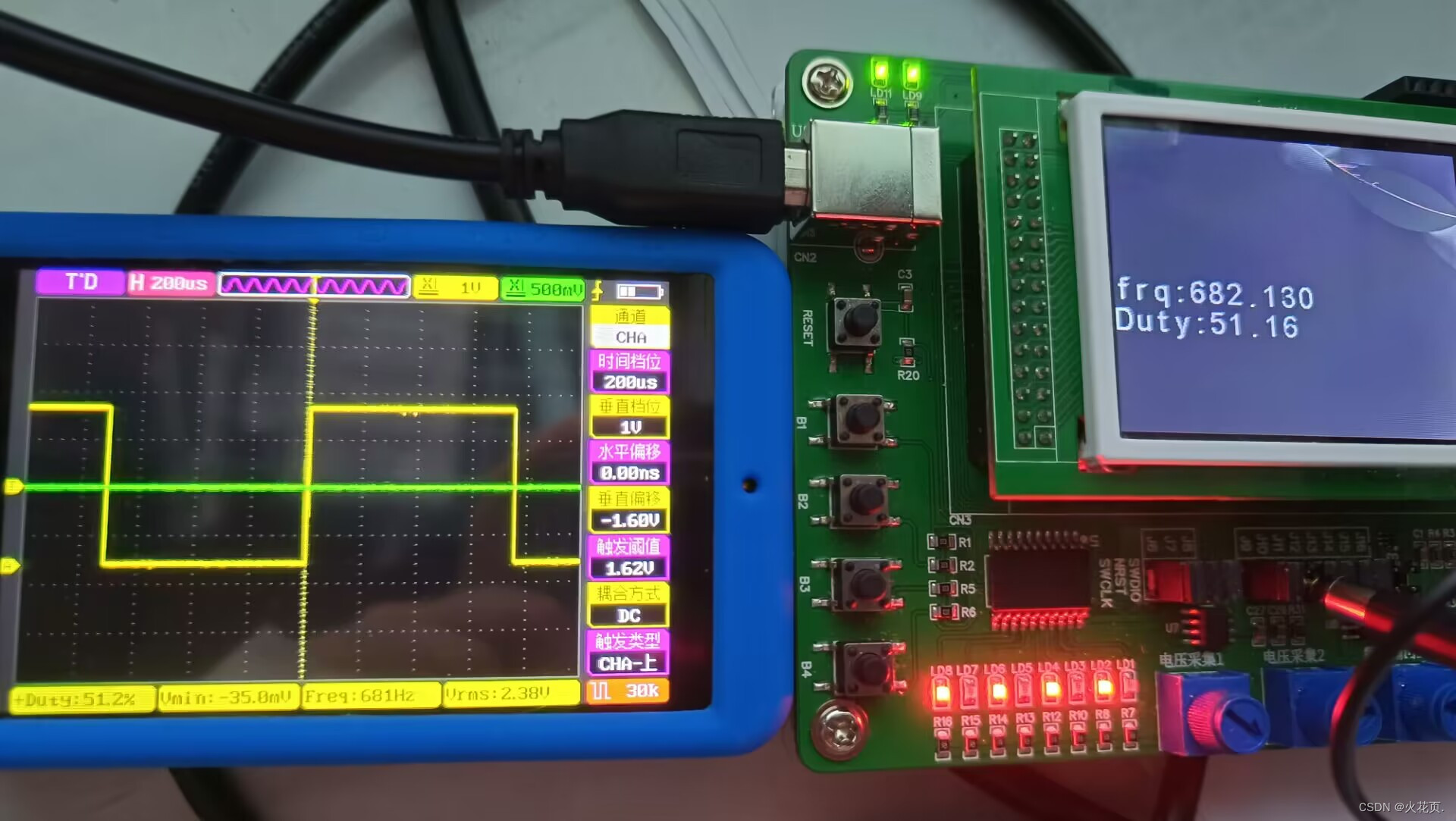
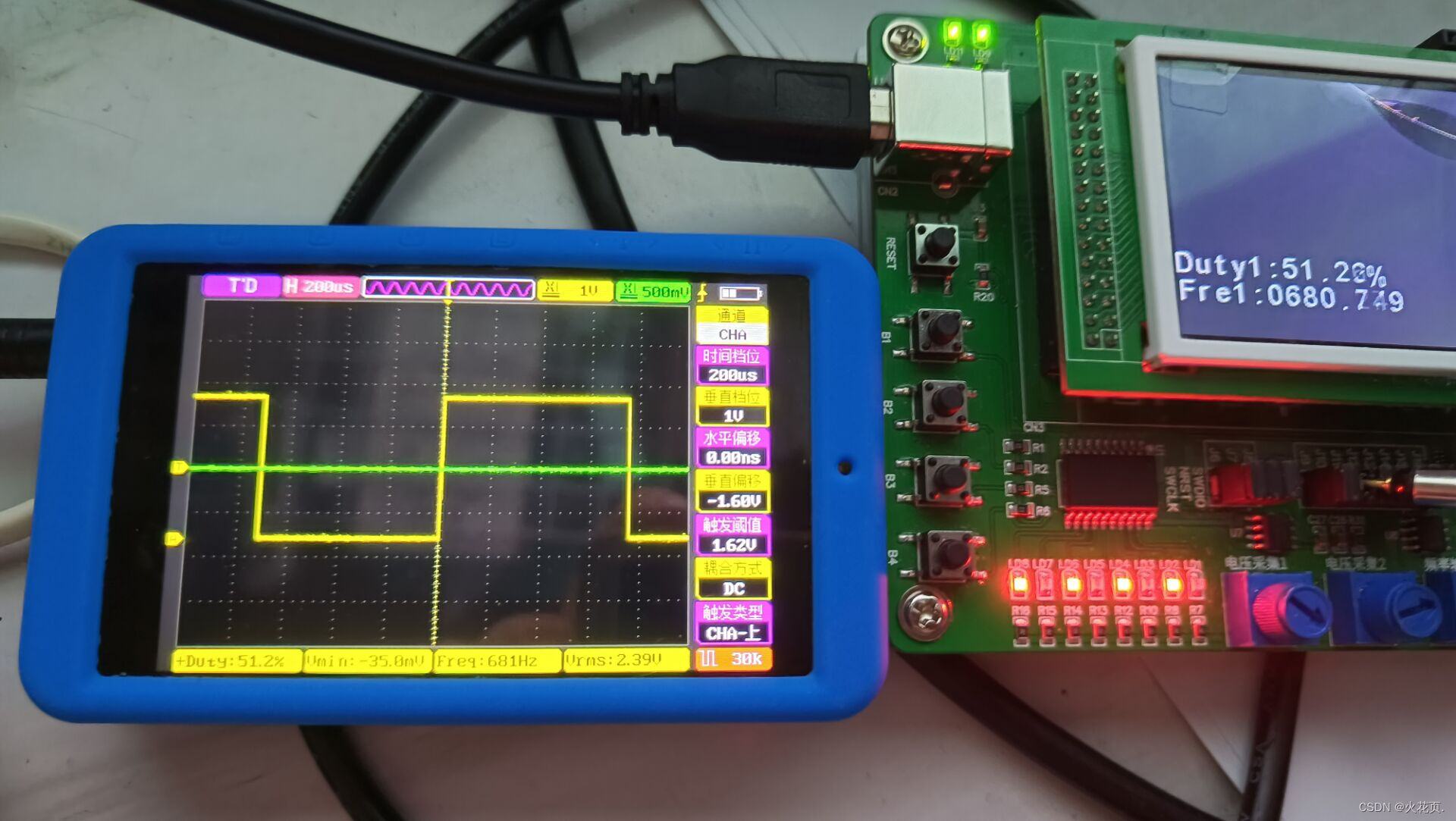
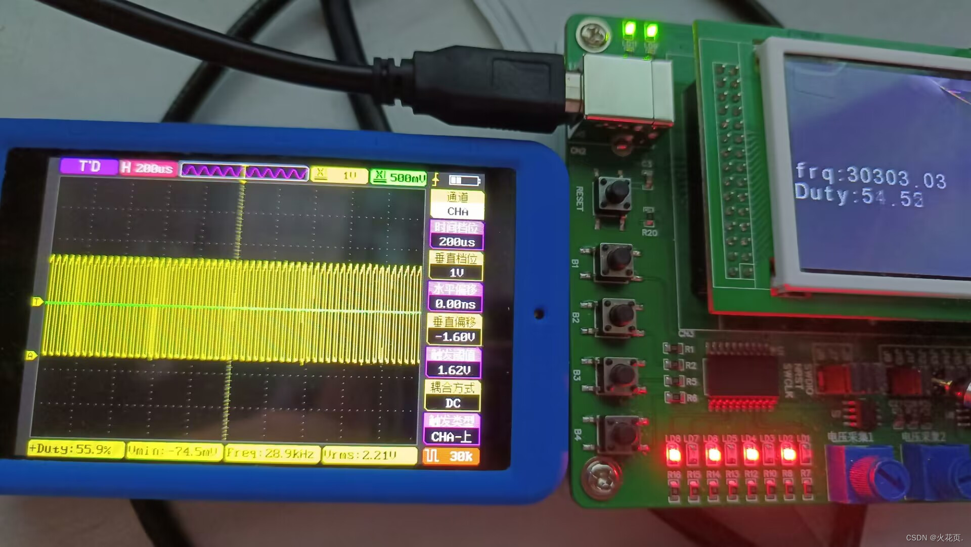
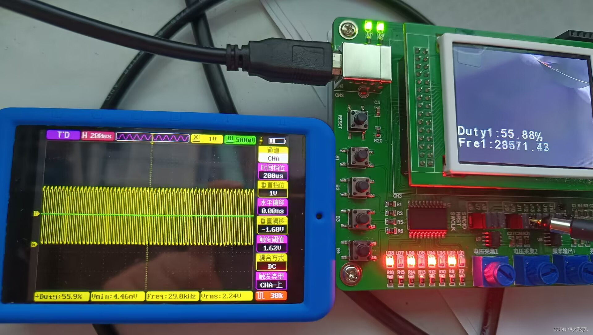
扩展模块写完之后,我在考虑双路IC采集占空比和本篇文章的采集算法哪个比较好,所以做了如下实验,实验步骤就是分别烧录两个工程改编的代码(改编就是把定时器和通道还有Cube配置一下),以R40为信号发生源和以示波器为标准采集比较两者采集的误差,现象如下六图:
低频(上图为本篇文章算法,下图为双路采集算法中的一路):
中频(上图为本篇文章算法,下图为双路采集算法中的一路):
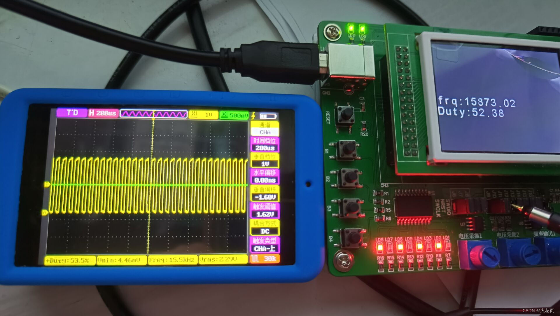
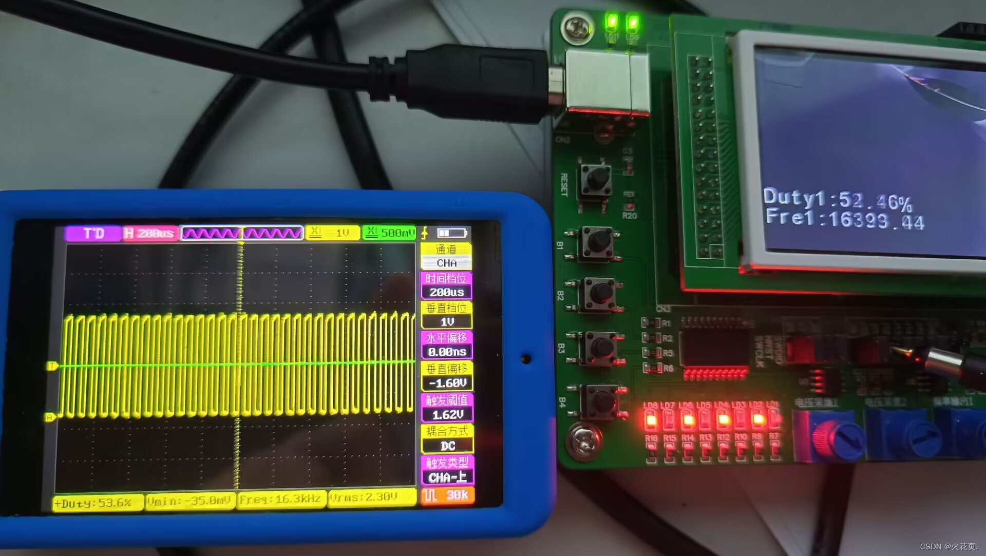
高频(上图为本篇文章算法,下图为双路采集算法中的一路):
(CSDN好像插不了五列表格…)
| 频率 | 单路采集频率误差 | 双路中其中一路采集频率误差 | 单路采集占空比误差和双路中其中一路采集占空比误差 |
|---|---|---|---|
| 低频 | 基本没有误差 | 基本没有误差 | 基本没有误差和基本没有误差 |
| 中频 | 300hz | 100hz | 1.1%和1.1% |
| 高频 | 1400hz | 500hz | 1.4%和1.2%(跳动比较快观察的可能有些不对) |
比较下来还是双路采集的写法比较有优势,尤其是在高频时最能体现,所以如果参加省赛的话,两种方法选一种方法就可以,如果参加国赛还是推荐用双路写法。
双路IC采集占空比


 4392
4392

 被折叠的 条评论
为什么被折叠?
被折叠的 条评论
为什么被折叠?
 到【灌水乐园】发言


