


文章目录
关于TOF相机,维基百科里有一个较好的概述,鉴于很多同学无法查看维基百科,所以此篇的内容为维基百科的翻译版。并加上一些个人的注解。
前言
A time-of-flight camera (ToF camera) is a range imaging camera system that employs time-of-flight techniques to resolve distance between the camera and the subject for each point of the image, by measuring the round trip time of an artificial light signal provided by a laser or an LED. Laser-based time-of-flight cameras are part of a broader class of scannerless LIDAR, in which the entire scene is captured with each laser pulse, as opposed to point-by-point with a laser beam such as in scanning LIDAR systems.1
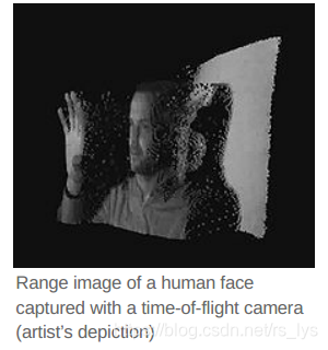
Time-of-flight camera products for civil applications began to emerge around 2000,2 as the semiconductor processes allowed the production of components fast enough for such devices. The systems cover ranges of a few centimeters up to several kilometers. The distance resolution is about 1 cm. The spatial resolution of time-of-flight cameras is generally low compared to standard 2D video cameras, with most commercially available devices at 320 × 240 pixels or less as of 2011.3456 Compared to other 3D laser scanning methods for capturing 3D images, TOF cameras operate more quickly by providing up to 160 operations per second.7
飞行时间相机(ToF相机)是采用飞行时间的距离成像相机系统通过测量由激光或LED提供的人造光信号的往返时间来解析相机和拍摄对象之间距离的技术。基于激光的飞行时间相机是更广泛的无扫描激光雷达类别的一部分,其中整个场景都是用每个激光脉冲捕获,而不是像扫描激光雷达系统那样用激光束逐点捕获。1【注:TOF不用有扫描的步骤,一次发射多个点覆盖场景并获取覆盖场景的全范围距离数据。】
民用TOF相机产品在2000年左右开始出现,2半导体工艺极大加快了这种器件的生产速度。这种系统的覆盖范围从几厘米到几公里,距离分辨率约为1厘米。与标准2D视频相比,飞行时间相机的空间分辨率通常较低,截至2011年,大多数商用设备的像素为320×240像素或更小。3 4 5 6与其他用于捕获3D图像的3D激光扫描方法相比,TOF相机速度更快,每秒可提供多达160次获取。7【注:TOF相机的特点是帧率高,分辨率低。】
设备种类(Types of devices)
Several different technologies for time-of-flight cameras have been developed.
RF-modulated light sources with phase detectors
Photonic Mixer Devices (PMD),8 the Swiss Ranger, and CanestaVision9 work by modulating the outgoing beam with an RF carrier, then measuring the phase shift of that carrier on the receiver side. This approach has a modular error challenge: measured ranges are modulo the RF carrier wavelength. The Swiss Ranger is a compact, short-range device, with ranges of 5 or 10 meters and a resolution of 176 x 144 pixels. With phase unwrapping algorithms, the maximum uniqueness range can be increased. The PMD can provide ranges up to 60 m. Illumination is pulsed LEDs rather than a laser.10 CanestaVision developer Canesta was purchased by Microsoft in 2010. The Kinect2 for Xbox One was based on ToF technology from Canesta.
Range gated imagers
These devices have a built-in shutter in the image sensor that opens and closes at the same rate as the light pulses are sent out. Because part of every returning pulse is blocked by the shutter according to its time of arrival, the amount of light received relates to the distance the pulse has traveled. The distance can be calculated using the equation, z = R (S2 − S1) / 2(S1 + S2) + R / 2 for an ideal camera. R is the camera range, determined by the round trip of the light pulse, S1 the amount of the light pulse that is received, and S2 the amount of the light pulse that is blocked.1112
The ZCam by 3DV Systems[1] is a range-gated system. Microsoft purchased 3DV in 2009. Microsoft’s second-generation Kinect sensor was developed using knowledge gained from Canesta and 3DV Systems.13
Similar principles are used in the ToF camera line developed by the Fraunhofer Institute of Microelectronic Circuits and Systems and TriDiCam. These cameras employ photodetectors with a fast electronic shutter.
The depth resolution of ToF cameras can be improved with ultra-fast gating intensified CCD cameras. These cameras provide gating times down to 200ps and enable ToF setup with sub-millimeter depth resolution.14
Range gated imagers can also be used in 2D imaging to suppress anything outside a specified distance range, such as to see through fog. A pulsed laser provides illumination, and an optical gate allows light to reach the imager only during the desired time period.15
Direct Time-of-Flight imagers
These devices measure the direct time-of-flight required for a single laser pulse to leave the camera and reflect back onto the focal plane array. Also known as “trigger mode”, the 3D images captured using this methodology image complete spatial and temporal data, recording full 3D scenes with single laser pulse. This allows rapid acquisition and rapid real-time processing of scene information. For time-sensitive autonomous operations, this approach has been demonstrated for autonomous space testing16 and operation such as used on the OSIRIS-REx Bennu asteroid sample and return mission17 and autonomous helicopter landing.1819
Advanced Scientific Concepts, Inc. provides application specific (e.g. aerial, automotive, space) Direct TOF vision systems20 known as 3D Flash LIDAR cameras. Their approach utilizes InGaAs Avalanche Photo Diode (APD) or PIN photodetector arrays capable of imaging laser pulse in the 980 nm to 1600 nm wavelengths.
已经开发了多种用于TOF相机的技术。
带有相位检测器的RF调制光源
Photonic Mixer Devices (PMD),8 Swiss Ranger和CanestaVision 9通过调制带有射频载波的输出光束,在接收器端测量该载波的相移。 该方法面对的挑战是模块化误差:测量范围是RF载波波长的模。 Swiss Ranger是一款紧凑的短距离设备,测距为5或10米,分辨率为176 x 144像素,使用相位展开算法,可以增加最大唯一性范围。 PMD可以提供最大60m的测距,照明光源采用脉冲LED而非激光。10 CanestaVision的开发商Canesta在2010年被Microsoft收购,Xbox One的Kinect2就是基于Canesta的TOF技术。
距离选通成像仪
这些设备在图像传感器中具有内置的快门,该快门以与发出光脉冲相同的速率打开和关闭。 由于每个返回脉冲的一部分会根据到达时间被快门遮挡,因此接收到的光量与脉冲的传播距离有关。 距离可以使用以下公式计算:对于理想的相机,z = R(S2-S1)/ 2(S1 + S2)+ R / 2。 R是相机范围,由光脉冲的往返行程确定,S1是接收到的光脉冲的数量,S2是被阻止的光脉冲的数量。11 12
3DV Systems的ZCam [1]是一个距离选通系统。微软在2009年收购了3DV。第二代Kinect传感器是基于从Canesta和3DV获得的经验开发的系统。13
弗劳恩霍夫微电子电路与系统研究所和TriDiCam开发的ToF相机系列使用了类似的原理。 这些相机使用带有快速电子快门的光电探测器。
使用超快速选通增强型CCD相机可以提高ToF相机的深度分辨率。
这些相机的选通时间低至200ps,并能够以亚毫米的深度分辨率进行ToF设置。14
距离选通成像器也可以用于2D成像中,以抑制指定距离范围之外的任何物体,例如透视雾。 脉冲激光提供照明,光闸仅在所需时间段内允许光到达成像器。15
直接TOF成像仪
这些设备测量单个激光脉冲离开相机并反射回焦平面阵列所需的直接飞行时间。 也称为“触发模式”,使用此方法捕获的3D图像可对空间和时间数据进行完整成像,并用单个激光脉冲记录完整的3D场景。这允许场景信息的快速获取和快速实时处理。 这种方法已被证明可用于对时间敏感的自主空间测试16和作业,比如用于OSIRIS-REx Bennu小行星样本和返回任务17以及直升机自主着陆。1819
Advanced Scientific Concepts,Inc.提供称为3D Flash LIDAR相机的特定于应用程序(例如,航空,汽车,太空)的直接TOF视觉系统20。 他们的方法利用InGaAs Avalanche Photo Diode (APD) 或PIN光电探测器阵列,能够对980 nm至1600 nm波长的激光脉冲成像。
部件(Components)
A time-of-flight camera consists of the following components:
Illumination unit: It illuminates the scene. For RF-modulated light sources with phase detector imagers, the light has to be modulated with high speeds up to 100 MHz, only LEDs or laser diodes are feasible. For Direct TOF imagers, a single pulse per frame (e.g. 30 Hz) is used. The illumination normally uses infrared light to make the illumination unobtrusive.
Optics: A lens gathers the reflected light and images the environment onto the image sensor (focal plane array). An optical band-pass filter only passes the light with the same wavelength as the illumination unit. This helps suppress non-pertinent light and reduce noise.
Image sensor: This is the heart of the TOF camera. Each pixel measures the time the light has taken to travel from the illumination unit (laser or LED) to the object and back to the focal plane array. Several different approaches are used for timing; see Types of devices above.
Driver electronics: Both the illumination unit and the image sensor have to be controlled by high speed signals and synchronized. These signals have to be very accurate to obtain a high resolution. For example, if the signals between the illumination unit and the sensor shift by only 10 picoseconds, the distance changes by 1.5 mm. For comparison: current CPUs reach frequencies of up to 3 GHz, corresponding to clock cycles of about 300 ps - the corresponding ‘resolution’ is only 45 mm.
Computation/Interface: The distance is calculated directly in the camera. To obtain good performance, some calibration data is also used. The camera then provides a distance image over some interface, for example USB or Ethernet.
TOF相机由以下部件组成:
照明单元:用于照明场景。 对于带有相位检测器成像器的RF调制光源,必须以高达100 MHz的高速调制光,只有LED或激光二极管才是可行的。 对于Direct TOF成像器,每帧使用单个脉冲(例如30 Hz)。 照明通常使用红外光使照明不引人注目。
光学器件:透镜收集反射的光并将环境成像到图像传感器(焦平面阵列)上。 光学带通滤光片仅使具有与照明单元相同波长的光通过。 这有助于抑制不相关的光线并减少噪声。
图像传感器:这是TOF相机的核心。 每个像素测量光从照明单元(激光或LED)传播到物体再回到焦平面阵列所花费的时间。 有多种不同的方法用于计时,参阅上面的设备类型。
驱动器电子设备:照明单元和图像传感器都必须由高速信号控制并同步。 这些信号必须非常准确才能获得高分辨率。 例如,如果照明单元和传感器之间的信号仅偏移10皮秒,则距离变化1.5毫米。 为了进行比较:当前的CPU达到高达3 GHz的频率,对应于大约300ps的时钟周期—相应的“分辨率”仅为45 mm。
计算/接口:距离直接在相机中计算。 为了获得良好的性能,还使用了一些校准数据。 摄像机通过某些接口(例如USB或以太网)提供距离图像。
原理(Principle)
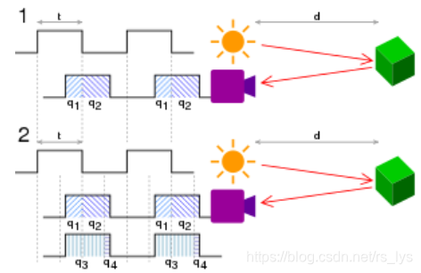
Principle of operation of a time-of-flight camera: In the pulsed method (1), the distance, d = ct/2*q2/(q1 + q2) , where c is the speed of light, t is the length of the pulse, q1 is the accumulated charge in the pixel when light is emitted and q2 is the accumulated charge when it is not. In the continuous-wave method (2), d = ct/2π arctanq3 - q4q1 - q2 .21
Diagrams illustrating the principle of a time-of-flight camera with analog timing
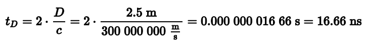
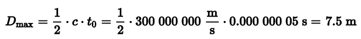
The simplest version of a time-of-flight camera uses light pulses or a single light pulse. The illumination is switched on for a very short time, the resulting light pulse illuminates the scene and is reflected by the objects in the field of view. The camera lens gathers the reflected light and images it onto the sensor or focal plane array. Depending upon the distance, the incoming light experiences a delay. As light has a speed of approximately c = 300,000,000 meters per second, this delay is very short: an object 2.5 m away will delay the light by:22
For amplitude modulated arrays, the pulse width of the illumination determines the maximum range the camera can handle. With a pulse width of e.g. 50 ns, the range is limited to
These short times show that the illumination unit is a critical part of the system. Only with special LEDs or lasers is it possible to generate such short pulses.
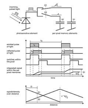
The single pixel consists of a photo sensitive element (e.g. a photo diode). It converts the incoming light into a current. In analog timing imagers, connected to the photo diode are fast switches, which direct the current to one of two (or several) memory elements (e.g. a capacitor) that act as summation elements. In digital timing imagers, a time counter, that can be running at several gigahertz, is connected to each photodetector pixel and stops counting when light is sensed.
In the diagram of an amplitude modulated array analog timer, the pixel uses two switches (G1 and G2) and two memory elements (S1 and S2). The switches are controlled by a pulse with the same length as the light pulse, where the control signal of switch G2 is delayed by exactly the pulse width. Depending on the delay, only part of the light pulse is sampled through G1 in S1, the other part is stored in S2. Depending on the distance, the ratio between S1 and S2 changes as depicted in the drawing.[9] Because only small amounts of light hit the sensor within 50 ns, not only one but several thousand pulses are sent out (repetition rate tR) and gathered, thus increasing the signal to noise ratio.
After the exposure, the pixel is read out and the following stages measure the signals S1 and S2. As the length of the light pulse is defined, the distance can be calculated with the formula:
In the example, the signals have the following values: S1 = 0.66 and S2 = 0.33. The distance is therefore:
In the presence of background light, the memory elements receive an additional part of the signal. This would disturb the distance measurement. To eliminate the background part of the signal, the whole measurement can be performed a second time with the illumination switched off. If the objects are further away than the distance range, the result is also wrong. Here, a second measurement with the control signals delayed by an additional pulse width helps to suppress such objects. Other systems work with a sinusoidally modulated light source instead of the pulse source.
For direct TOF imagers, such as 3D Flash LIDAR, a single short pulse from 5 to 10 ns is emitted by the laser. The T-zero event (the time the pulse leaves the camera) is established by capturing the pulse directly and routing this timing onto the focal plane array. T-zero is used to compare the return time of the returning reflected pulse on the various pixels of the focal plane array. By comparing T-zero and the captured returned pulse and comparing the time difference, each pixel accurately outputs a direct time-offlight measurement. The round trip of a single pulse for 100 meters is 660 ns. With a 10 ns pulse, the scene is illuminated and the range and intensity captured in less than 1 microsecond.
TOF相机的最简单形式使用光脉冲或单个光脉冲。 短时间内开启照明,所产生的光脉冲照亮场景并被视野中的物体反射, 相机镜头会收集反射的光并将其成像到传感器或焦平面阵列上。入射光会根据距离产生延迟,由于光的速度约为c = 300,000,000米/秒,因此延迟非常短:距离2.5 m的物体会将光延迟以下时间:22
对于调幅阵列,照明的脉冲宽度决定了相机可以处理的最大范围。 脉冲宽度为 50 ns,范围仅限于
这么短暂的时间表明照明单元是系统的关键部分。只有使用特殊的LED或激光,才可能产生这样的短脉冲。
单个像素由感光元件(例如,光电二极管)组成。 它将入射光转换为电流。 在模拟定时成像器中,与光电二极管相连的是快速开关,该快速开关将电流引导至用作求和元件的两个(或几个)存储元件(例如电容器)之一。 在数字定时成像器中,可以以几千兆赫运行的计时器连接到每个光电探测器像素,并在检测到光时停止计数。
在调幅阵列模拟计时器的图中,像素使用两个开关(G1和G2)和两个存储元件(S1和S2)。 开关由具有与光脉冲相同长度的脉冲控制,其中,开关G2的控制信号正好延迟了脉冲宽度。 根据延迟,仅一部分光脉冲通过S1中的G1进行采样,另一部分存储在S2中。 根据距离的不同,S1和S2之间的比例也会发生变化,如图所示。9 由于在50 ns内只有少量的光射到传感器上,因此不仅发出一个脉冲,而是发出数千个脉冲(重复率tR)并聚集,从而提高了信噪比。
曝光后,读出像素,随后测量信号S1和S2。 定义了光脉冲的长度后,可以使用以下公式计算距离:
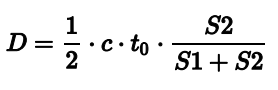
在此示例中,信号具有以下值:S1 = 0.66和S2 = 0.33。 因此,距离为:
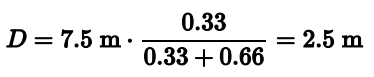
在存在背景光的情况下,存储元件会接收多余的信号,这会干扰距离测量。为了消除信号的背景部分,可以在关闭照明的情况下第二次执行整个测量。 如果物体距离距离范围远,则结果也是错误的,通过将控制信号延迟一个额外的脉冲宽度进行第二次测量有助于抑制此类物体。 其他系统使用正弦调制光源代替脉冲源。
对于直接的TOF成像仪,例如3D Flash LIDAR,激光会发出5到10ns的单个短脉冲。 通过直接捕获脉冲并将此时序路由到焦平面阵列来建立T-zero事件(脉冲离开相机的时间)。 T-zero用于比较焦平面阵列各个像素上返回反射脉冲的返回时间。通过比较T-zero和捕获的返回脉冲并比较时间差,每个像素可以准确地输出直接的飞行时间测量值。 单脉冲100米的往返行程为660 ns。 使用10 ns的脉冲,场景被照亮,并且在不到1微秒的时间内捕获范围和强度。
优点(Advantages)
Simplicity
In contrast to stereo vision or triangulation systems, the whole system is very compact: the illumination is placed just next to the lens, whereas the other systems need a certain minimum base line. In contrast to laser scanning systems, no mechanical moving parts are needed.
Efficient distance algorithm
It is a direct process to extract the distance information out of the output signals of the TOF sensor. As a result, this task uses only a small amount of processing power, again in contrast to stereo vision, where complex correlation algorithms are implemented. After the distance data has been extracted, object detection, for example, is also a straightforward process to carry out because the algorithms are not disturbed by patterns on the object.
Speed
Time-of-flight cameras are able to measure the distances within a complete scene with a single shot. As the cameras reach up to 160 frames per second, they are ideally suited to be used in real-time applications.
简单
与立体视觉或三角测量系统相比,整个系统非常紧凑:照明仅放置在镜头旁边,而其他系统则需要一定的最小基线。 与激光扫描系统相比,不需要机械运动部件。
高效的测距算法
从TOF传感器的输出信号中提取距离信息是直接的过程。 不像立体视觉中需要复杂的算法,该任务仅使用少量处理能力。在提取距离数据之后,类似于物体检测任务也是一种简单的执行过程,因为算法不受物体上图案的干扰。
速度
TOF相机能够一次获取完整场景中的距离,由于摄像头每秒可达到160帧,因此非常适合在实时应用中使用。
缺点(Disadvantages)
Background light
When using CMOS or other integrating detectors or sensors that use visible or near infra-red light (400 nm - 700 nm), although most of the background light coming from artificial lighting or the sun is suppressed, the pixel still has to provide a high dynamic range. The background light also generates electrons, which have to be stored. For example, the illumination units in many of today’s TOF cameras can provide an illumination level of about 1 watt. The Sun has an illumination power of about 1050 watts per square meter, and 50 watts after the optical band-pass filter. Therefore, if the illuminated scene has a size of 1 square meter, the light from the sun is 50 times stronger than the modulated signal. For nonintegrating TOF sensors that do not integrate light over time and are using near-infrared detectors (InGaAs) to capture the short laser pulse, direct viewing of the sun is a non issue because the image is not integrated over time, rather captured within a short acquisition cycle typically less than 1 microsecond. Such TOF sensors are used in space applications17 and in consideration for automotive applications.23
Interference
In certain types of TOF devices (but not all of them), if several time-of-flight cameras are running at the same time, the TOF cameras may disturb each other’s measurements. There exist several possibilities for dealing with this problem:Time multiplexing: A control system starts the measurement of the individual cameras consecutively, so that only one illumination unit is active at a time.
Different modulation frequencies: If the cameras modulate their light with different modulation frequencies, their light is collected in the other systems only as background illumination but does not disturb the distance measurement.For Direct TOF type cameras that use a single laser pulse for illumination, because the single laser pulse is short (e.g. 10 nanoseconds), the round trip TOF to and from the objects in the field of view is correspondingly short (e.g. 100 meters = 660 ns TOF round trip). For an imager capturing at 30 Hz, the probability of an interfering interaction is the time that the camera acquisition gate is open divided by the time between laser pulses or approximately 1 in 50,000 (0.66 μs divided by 33 ms).
Multiple reflections
In contrast to laser scanning systems where a single point is illuminated, the time-of-flight cameras illuminate a whole scene. For a phase difference device (amplitude modulated array), due to multiple reflections, the light may reach the objects along several paths. Therefore, the measured distance may be greater than the true distance. Direct TOF imagers are vulnerable if the light is reflecting from a specular surface. There are published papers available that outline the strengths and weaknesses of the various TOF devices and approaches.24
背景光
当使用CMOS或其他使用可见光或近红外光(400 nm-700 nm)的集成检测器或传感器时,尽管大部分来自人工照明或太阳的背景光有采用手段抑制,但像素仍然必须提供较高的动态范围。背景光也会产生电子而被存储,例如,当今许多TOF相机中的照明单元可以提供大约1瓦的照明水平,太阳的照明功率约为每平方米1050瓦,在光学带通滤波器之后的照明功率为50瓦,因此,如果照明场景的大小为1平方米,则来自太阳的光比调制信号强50倍。对于非集成TOF传感器,它不会随时间推移而积聚光,而是使用近红外检测器(InGaAs)来捕获短激光脉冲,因此直接观察太阳是没有问题的,因为图像不会随时间而积聚,而是在一个较短的周期采集(通常小于1微秒)。这种TOF传感器用于空间应用[17],并考虑用于汽车应用。23
干扰
在某些类型的TOF设备(但不是全部)中,如果同时运行多个TOF摄像头,则TOF摄像头可能会干扰彼此的测量。有几种可能的解决方案:
时分复用:一个控制系统会连续开始测量各个摄像机,因此一次仅激活一个照明单元。
不同的调制频率:如果摄像机以不同的调制频率调制其光,则它们的光在其他系统中仅作为背景照明收集,而不会干扰距离测量。
对于使用单个激光脉冲进行照明的直接TOF型相机,由于单个激光脉冲很短(例如10纳秒),因此往返于视场中物体的TOF往返行程相应较短(例如100米 = 660 ns TOF往返)。对于以30 Hz捕获的成像器,发生干扰相互作用的可能性是相机采集门打开的时间除以激光脉冲之间的时间,大约是1/50,000(0.66μs除以33 ms)。
多重反射
与照亮单个点的激光扫描系统相反,飞行时间相机照亮了整个场景。对于相位差设备(调幅阵列),由于多次反射,光可能会沿着多条路径到达对象, 因此测得的距离可能大于真实距离。如果光从镜面反射,则直接TOF成像仪很容易出现问题。 有公开的论文概述了各种TOF装置和方法的优缺点。24
应用(Applications)
Automotive applications
Time-of-flight cameras are used in assistance and safety functions for advanced automotive applications such as active pedestrian safety, precrash detection and indoor applications like out-ofposition (OOP) detection.2526
Human-machine interfaces and gaming
As time-of-flight cameras provide distance images in real time, it is easy to track movements of humans. This allows new interactions with consumer devices such as televisions. Another topic is to use this type of cameras to interact with games on video game consoles.27 The second-generation Kinect sensor originally included with the Xbox One console used a time-of-flight camera for its range imaging,28 enabling natural user interfaces and gaming applications using computer vision and gesture recognition techniques. Creative and Intel also provide a similar type of interactive gesture time-of-flight camera for gaming, the Senz3D based on the DepthSense 325 camera of Softkinetic.29. Infineon and PMD Technologies enable tiny integrated 3D depth cameras for close-range gesture control of consumer devices like all-in-one PCs and laptops (Picco flexx and Picco monstar cameras).30
Smartphone cameras
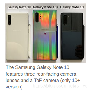
As of 2019, several smartphones include time-of-flight cameras. These are mainly used to improve the quality of photos by providing the camera software with information about foreground and background.31
Measurement and machine vision
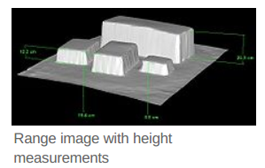
Other applications are measurement tasks, e.g. for the fill height in silos. In industrial machine vision, the time-of-flight camera helps to classify and locate objects for use by robots, such as items passing by on a conveyor. Door controls can distinguish easily between animals and humans reaching the door.
Robotics
Another use of these cameras is the field of robotics: Mobile robots can build up a map of their surroundings very quickly, enabling them to avoid obstacles or follow a leading person. As the distance calculation is simple, only little computational power is used.
Earth topography
ToF cameras have been used to obtain digital elevation models of the Earth’s surface topography,32 for studies in geomorphology.
汽车应用
TOF相机用于辅助和安全功能,用于先进的汽车应用,例如主动行人安全,事前碰撞检测和室内应用,例如错位(OOP)检测。25 26
人机界面和游戏
TOF相机实时提供距离图像,因此很容易跟踪人类的运动。 这允许与诸如电视之类的消费类设备进行新的交互。 另一个主题是使用这种类型的相机与视频游戏机上的游戏进行交互。27 Xbox One控制台最初随附的第二代Kinect传感器使用TOF相机进行距离成像,28使用计算机视觉和手势识别技术,实现了自然的用户界面和游戏应用程序。Creative和Intel还为游戏提供了类似类型的交互式手势TOF相机,即基于Softkinetic的DepthSense 325相机的Senz3D。29。 Infineon 和PMD Technologies 使微型集成3D深度相机能够对诸如多合一PC和笔记本电脑(Picco flexx和Picco monstar相机)等消费类设备进行近距离手势控制。30
智能手机相机
截至2019年,几款智能手机均包含TOF相机。这些主要用于通过为相机软件提供有关前景和背景的信息来提高照片的质量。31
测量与机器视觉
其他应用是测量任务,例如筒仓的填充高度。在工业机器视觉中,TOF摄像机有助于对机器人使用的对象进行分类和定位,例如在传送带上经过的物品。门控制器可以轻松地区分动物和人。
机器人
这些相机的另一个用途是机器人领域:移动机器人可以非常迅速地绘制周围环境的地图,从而使其能够避开障碍物或跟随领导者。 由于距离计算很简单,因此仅使用很少的计算能力。
地球地形
TOF相机已用于获取地球表面地形的数字高程模型,32 用于地貌研究。
品牌(Brands)
Active brands (as of 2011)
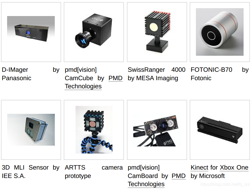
3D Flash LIDAR Cameras and Vision Systems by Advanced Scientific Concepts, Inc. for aerial, automotive and space applications
DepthSense - TOF cameras and modules, including RGB sensor and microphones by SoftKinetic
IRMA MATRIX - TOF camera, used for automatic passenger counting on mobile and stationary applications by iris-GmbH
Kinect - hands-free user interface platform by Microsoft for video game consoles and PCs, using time-of-flight cameras in its second generation of sensor devices.28
pmd - camera reference designs and software (pmd[vision], including TOF modules [CamBoard]) and TOF imagers (PhotonICs) by PMD Technologies
real.IZ 2+3D - High-resolution SXGA (1280×1024) TOF camera developed by startup company odos imaging, integrating conventional image capture with TOF ranging in the same sensor. Based on technology developed at Siemens.
Senz3D - TOF camera by Creative and Intel based on DepthSense 325 camera of Softkinetic, used for gaming.29
SICK - 3D industrial TOF cameras (Visionary-T) for industrial applications and software33
3D MLI Sensor - TOF imager, modules, cameras, and software by IEE (International Electronics & Engineering), based on modulated light intensity (MLI)
TOFCam Stanley - TOF camera by Stanley Electric
TriDiCam - TOF modules and software, the TOF imager originally developed by Fraunhofer Institute of Microelectronic Circuits and Systems, now developed by the spin out company TriDiCam
Hakvision - TOF stereo camera
Defunct brands
CanestaVision[34] - TOF modules and software by Canesta (company acquired by Microsoft in 2010)
D-IMager - TOF camera by Panasonic Electric Works
OptriCam - TOF cameras and modules by Optrima (rebranded DepthSense prior to SoftKinetic merger in 2011)
ZCam - TOF camera products by 3DV Systems, integrating full-color video with depth information (assets sold to Microsoft in 2009)
SwissRanger - an industrial TOF-only camera line originally by the Centre Suisse d’Electronique et Microtechnique, S.A. (CSEM), now developed by Mesa Imaging (Mesa Imaging acquired by Heptagon in 2014)
Fotonic - TOF cameras and software powered by Panasonic CMOS chip (Fotonic acquired by Autoliv in 2018)
进一步阅读(Further reading)
Hansard, Miles; Lee, Seungkyu; Choi, Ouk; Horaud, Radu (2012). “Time-of-flight cameras: Principles, Methods and Applications” (http://hal.inria.fr/docs/00/72/56/54/PDF/TOF.pdf)(PDF). SpringerBriefs in Computer Science. doi:10.1007/978-1-4471-4658-2 (https://doi.org/10.1007%2F978-1-4471-4658-2). ISBN 978-1-4471-4657-5. “This book describes a variety of recent research into time-of-flight imaging: […] the underlying measurement principle […] the associated sources of error and ambiguity […] the geometric calibration of time-of-flight cameras, particularly when used in combination with ordinary color cameras […and] use time-of-flight data in conjunction with traditional stereo matching techniques. The five chapters, together, describe a complete depth and color 3D reconstruction pipeline.”
参考文献(References)
Iddan, Gavriel J.; Yahav, Giora (2001-01-24). “3D imaging in the studio (and elsewhere…)” (https://web.archive.org/web/20090612071500/http://www.3dvsystems.com/technology/3D%20Imaging%20in%20the%20studio.pdf) (PDF). Proceedings of SPIE. 4298. San Jose,CA: SPIE (published 2003-04-29). p. 48. doi:10.1117/12.424913 (https://doi.org/10.1117%2F12.424913). Archived from the original (http://www.3dvsystems.com/technology/3D%20Imaging%20in%20the%20studio.pdf) (PDF) on 2009-06-12. Retrieved 2009-08-17. “The [timeof-flight] camera belongs to a broader group of sensors known as scanner-less LIDAR (i.e.laser radar having no mechanical scanner); an early [1990] example is [Marion W.] Scott and his followers at Sandia.” ↩︎ ↩︎
“Product Evolution” (https://web.archive.org/web/20090228203547/http://www.3dvsystems.com/technology/product.html#1). 3DV Systems. Archived from the original (http://www.3dvsystems.com/technology/product.html#1) on 2009-02-28. Retrieved 2009-02-19. “Z-Cam, the first depth video camera, was released in 2000 and was targeted primarily at broadcasting organizations.” ↩︎ ↩︎
Schuon, Sebastian; Theobalt, Christian; Davis, James; Thrun, Sebastian (2008-07-15). “High-quality scanning using time-of-flight depth superresolution” (http://www-cs.stanford.edu/people/theobalt/TOF_CV_Superresolution_final.pdf) (PDF). IEEE Computer Society Conference on Computer Vision and Pattern Recognition Workshops, 2008. Institute of Electrical and Electronics Engineers. pp. 1–7. CiteSeerX 10.1.1.420.2946 (https://citeseerx.ist.psu.edu/viewdoc/summary?doi=10.1.1.420.2946). doi:10.1109/CVPRW.2008.4563171 (https://doi.org/10.1109%2FCVPRW.2008.4563171). ISBN 978-1-4244-2339-2. Retrieved 2009 07-31. “The Z-cam can measure full frame depth at video rate and at a resolution of 320×240 pixels.” ↩︎ ↩︎
“Canesta’s latest 3D Sensor - “Cobra” … highest res CMOS 3D depth sensor in the world” (https://www.youtube.com/watch?v=5_PVx1NbUZQ) (Flash Video). Sunnyvale, California: Canesta. 2010-10-25. “Canesta “Cobra” 320 x 200 Depth Sensor, capable of 1mm depth resolution, USB powered, 30 to 100 fps […] The complete camera module is about the size of a silver dollar” ↩︎ ↩︎
“SR4000 Data Sheet” (http://www.mesa-imaging.ch/dlm.php?fname=pdf/SR4000_Data_Sheet.pdf) (PDF) (Rev 2.6 ed.). Zürich, Switzerland: Mesa Imaging. August 2009: 1. Retrieved 2009-08-18. “176 x 144 pixel array (QCIF)” ↩︎ ↩︎
“PMD[vision] CamCube 2.0 Datasheet” (https://web.archive.org/web/20120225210428/http://www.pmdtec.com/fileadmin/pmdtec/downloads/documentation/datasheet_camcube.pdf) (PDF) (No. 20090601 ed.). Siegen, Germany: PMD Technologies. 2009-06-01: 5. Archived from the original (http://www.pmdtec.com/fileadmin/pmdtec/downloads/documentation/datasheet_camcube.pdf) (PDF) on 2012-02-25. Retrieved 2009-07-31. “Type of Sensor: PhotonICs PMD 41k-S (204 x 204)” ↩︎ ↩︎
http://ww2.bluetechnix.com/en/products/depthsensing/list/argos/ ↩︎ ↩︎
Christoph Heckenkamp: Das magische Auge - Grundlagen der Bildverarbeitung: Das PMD Prinzip (http://www.inspect online.com/whitepaper/das-magische-auge). In: Inspect. Nr. 1, 2008, S. 25–28. ↩︎ ↩︎
Gokturk, Salih Burak; Yalcin, Hakan; Bamji, Cyrus (24 January 2005). “A Time-Of-Flight Depth Sensor - System Description, Issues and Solutions” (https://web.archive.org/web/20070623233559/http://www.canesta.com/assets/pdf/technicalpapers/CVPR_Submission_TOF.pdf) (PDF). IEEE Computer Society Conference on Computer Vision and Pattern Recognition Workshops, 2004: 35–45. doi:10.1109/CVPR.2004.291 (https://doi.org/10.1109%2FCVPR.2004.291). Archived from the original (http://www.canesta.com/assets/pdf/technicalpapers/CVPR_Submission_TOF.pdf) (PDF) on 2007-06-23. Retrieved 2009-07-31. “The differential structure accumulates photo-generated charges in two collection nodes using two modulated gates. The gate modulation signals are synchronized with the light source, and hence depending on the phase of incoming light, one node collects more charges than the other. At the end of integration, the voltage difference between the two nodes is read out as a measure of the phase of the reflected light.” ↩︎ ↩︎ ↩︎
“Mesa Imaging - Products” (http://www.mesa-imaging.ch). August 17, 2009. ↩︎ ↩︎
US patent 5081530 (https://worldwide.espacenet.com/textdoc?DB=EPODOC&IDX=US5081530), Medina, Antonio, “Three Dimensional Camera and Rangefinder”, issued 1992-01-14, assigned to Medina, Antonio ↩︎ ↩︎
Medina A, Gayá F, Pozo F (2006). “Compact laser radar and three-dimensional camera”. J. Opt. Soc. Am. A. 23 (4): 800–805. Bibcode:2006JOSAA…23…800M (https://ui.adsabs.harvard.edu/abs/2006JOSAA…23…800M). doi:10.1364/JOSAA.23.000800 (https://doi.org/10.1364%2FJOSAA.23.000800). PMID 16604759 (https://pubmed.ncbi.nlm.nih.gov/16604759). ↩︎ ↩︎
“Kinect for Windows developer’s kit slated for November, adds ‘green screen’ technology” (http://www.pcworld.com/article/2042958/kinect-for-windows-developers-kit-slated-for-november-adds-green-screen-technology.html). PCWorld. 2013-06-26. ↩︎ ↩︎
“Submillimeter 3-D Laser Radar for Space Shuttle Tile Inspection.pdf” (http://www.stanfordcomputeroptics.com/download/Submillimeter%203-D%20Laser%20Radar%20for%20Space%20Shuttle%20Tile%20Inspection.pdf) (PDF). ↩︎ ↩︎
“Sea-Lynx Gated Camera - active laser camera system” (https://web.archive.org/web/20100813110630/http://www.laseroptronix.se/gated/sealynx.pdf) (PDF). Archived from the original (http://www.laseroptronix.se/gated/sealynx.pdf) (PDF) on 2010-08-13. ↩︎ ↩︎
Reisse, Robert; Amzajerdian, Farzin; Bulyshev, Alexander; Roback, Vincent (4 June 2013). “Helicopter flight test of 3D imaging flash LIDAR technology for safe, autonomous, and precise planetary landing” (https://ntrs.nasa.gov/archive/nasa/casi.ntrs.nasa.gov/201300134
72.pdf) (PDF). Laser Radar Technology and Applications XVIII. 8731: 87310H. doi:10.1117/12.2015961 (https://doi.org/10.1117%2F12.2015961). hdl:2060/20130013472 (https://hdl.handle.net/2060%2F20130013472). ↩︎ ↩︎“ASC’s 3D Flash LIDAR camera selected for OSIRIS-REx asteroid mission” (http://www.nasaspaceflight.com/2012/05/ascs-lidar-camera-osiris-rex-asteroid-mission/). NASASpaceFlight.com. 2012-05-13. ↩︎ ↩︎ ↩︎
“Autonomous Aerial Cargo/Utility System Program” (https://archive.today/20140406180528/http://www.onr.navy.mil/en/Science-Technology/Departments/Code-35/All-Programs/aerospace-research-351/Autonomous-Aerial-Cargo-Utility-AACUS.aspx). Office of Naval Research. Archived from the original (http://www.onr.navy.mil/en/Science-Technology/Departments/Code-35/All Programs/aerospace-research-351/Autonomous-Aerial-Cargo-Utility-AACUS.aspx) on 2014-04-06. ↩︎ ↩︎
“Products” (http://www.advancedscientificconcepts.com/products/overview.html). Advanced Scientific Concepts. ↩︎ ↩︎
“Time-of-Flight Camera — An Introduction" (http://eu.mouser.com/applications/time-of-flight-robotics). Mouser Electronics. ↩︎
“CCD/CMOS Lock-In Pixel for Range Imaging: Challenges, Limitations and State-of-the-Art” (https://pdfs.semanticscholar.org/1b8d/d5859923001073d49613e27b539ec6686463.pdf) - CSEM ↩︎ ↩︎
“Automotive” (http://www.advancedscientificconcepts.com/applications/automotive.htm). Advanced Scientific Concepts. ↩︎ ↩︎
Aue, Jan; Langer, Dirk; Muller-Bessler, Bernhard; Huhnke, Burkhard (2011-06-09). “Efficient segmentation of 3D LIDAR point clouds handling partial occlusion” (https://ieeexplore.ieee.org/document/5940442/). 2011 IEEE Intelligent Vehicles Symposium (IV). Baden-Baden, Germany: IEEE. doi:10.1109/ivs.2011.5940442 (https://doi.org/10.1109%2Fivs.2011.5940442). ISBN 978-1-4577-08909. ↩︎ ↩︎
Hsu, Stephen; Acharya, Sunil; Rafii, Abbas; New, Richard (25 April 2006). Performance of a Time-of-Flight Range Camera for Intelligent Vehicle Safety Applications (https://web.archive.org/web/20061206105733/http://www.canesta.com/assets/pdf/technicalpapers/canesta_amaa06_paper_final1.pdf) (PDF). Advanced Microsystems for Automotive Applications 2006. VDI-Buch. Springer. pp. 205–219. CiteSeerX 10.1.1.112.6869 (https://citeseerx.ist.psu.edu/viewdoc/summary?doi=10.1.1.112.6869). doi:10.1007/3-540-33410-6_16 (https://doi.org/10.1007%2F3-540-33410-6_16). ISBN 978-3-540-33410-1. Archived from the original (http://www.canesta.com/assets/pdf/technicalpapers/canesta_amaa06_paper_final1.pdf) (PDF) on 2006-12-06. Retrieved 2018-06-25. ↩︎ ↩︎
Elkhalili, Omar; Schrey, Olaf M.; Ulfig, Wiebke; Brockherde, Werner; Hosticka, Bedrich J. (September 2006), “A 64x8 pixel 3-D CMOS time-of flight image sensor for car safety applications” (http://publica.fraunhofer.de/documents/N-48683.html), European Solid State Circuits Conference 2006, pp. 568–571, doi:10.1109/ESSCIR.2006.307488 (https://doi.org/10.1109%2FESSCIR.2006.307488), ISBN 978-1-4244-0302-8, retrieved 2010-03-05 ↩︎ ↩︎
Captain, Sean (2008-05-01). “Out of Control Gaming” (http://www.popsci.com/gear-gadgets/article/2008-05/out-control-gaming). PopSci.com. Popular Science. Retrieved 2009-06-15. ↩︎ ↩︎
Rubin, Peter (2013-05-21). “Exclusive First Look at Xbox One” (https://www.wired.com/gadgetlab/2013/05/xbox-one/). Wired. Wired Magazine. Retrieved 2013-05-22. ↩︎ ↩︎ ↩︎
Sterling, Bruce (2013-06-04). “Augmented Reality: SoftKinetic 3D depth camera and Creative Senz3D Peripheral Camera for Intel devices” (https://www.wired.com/beyond_the_beyond/2013/06/augmented-reality-softkinetic-3d-depth-camera-and-creative-senz3d-peripheral-camera-for-intel-devices/). Wired Magazine. Retrieved 2013-07-02. ↩︎ ↩︎ ↩︎
Lai, Richard. “PMD and Infineon to enable tiny integrated 3D depth cameras (hands-on)” (https://www.engadget.com/2013/06/06/pmd-infineon-camboard-pico-s-3d-depth-camera/). Engadget. Retrieved 2013-10-09. ↩︎ ↩︎
Heinzman, Andrew (2019-04-04). “What Is a Time of Flight (ToF) Camera, and Why Does My Phone Have One?” (https://www.howtogeek.com/409704/what-is-a-time-of-flight-tof-camera-and-why-does-my-phone-have-one/). How-To Geek. ↩︎ ↩︎
Nitsche, M.; Turowski, J. M.; Badoux, A.; Rickenmann, D.; Kohoutek, T. K.; Pauli, M.; Kirchner, J. W. (2013). “Range imaging: A new method for high-resolution topographic measurements in small- and medium-scale field sites”. Earth Surface Processes and
Landforms. 38 (8): 810. Bibcode:2013ESPL…38…810N (https://ui.adsabs.harvard.edu/abs/2013ESPL…38…810N). doi:10.1002/esp.3322 (https://doi.org/10.1002%2Fesp.3322). ↩︎ ↩︎TBA. “SICK - Visionary-T y Visionary-B: 3D de un vistazo - Handling&Storage” (http://www.handling-storage.com/sick—visionary-t-y-visionary-b–3d-de-un-vistazo.html). www.handlingstorage.com (in Spanish). Retrieved 2017-04-18. ↩︎


 1158
1158

 被折叠的 条评论
为什么被折叠?
被折叠的 条评论
为什么被折叠?
 到【灌水乐园】发言


