


基于05/31/2018
Gary Sullivan and Stephen Estrop
Microsoft Corporation
April 2002, updated November 2008
此篇描述了在 Windows 系统中渲染时建议使用的 8bit YUV 格式。本文介绍了在 YUV 和 RGB 格式之间转换的技术,也提供了对 YUV 格式进行采样的方法。本文适用于 anyone working with YUV video decoding or rendering in Windows.
简介
在整个视频行业中定义了许多 YUV 格式。本文指出了在 Windows 中进行视频播放所建议使用的 8 位 YUV 格式。建议解码器提供商和显示供应商支持本文中描述的格式。本文不涉及 YUV 格式的其他用途,例如摄影。
本文中描述的格式均使用 8bit 来对每个像素的 Y 通道(也称 luma 通道)进行编码,对于每个 U 和 V 采样也使用 8bit 进行编码。但是对于大多数格式来说,平均每个像素使用不到 24bit,因为它们包含的 U 和 V 采样少于 Y。本文不包含 10bit 或者更高 Y 通道的格式(见下一篇)。
注意
对于本文而言,术语 U 等效 Cb,属于 V 等效 Cr。
本文包含以下几部分:
- YUV Sampling. 介绍最常见的 YUV 采样技术。
- Surface Definitions. 介绍建议的 YUV 格式。
- Color Space and Chroma Sampling Rate Conversions. 提供了一些在 YUV 和 RGB 格式之间转换以及在不同 YUV 格式之间转换的指南。
- Identifying YUV Formats in Media Foundation. 说明如何在 Media Foundation 中描述 YUV 格式类型。
YUV Sampling
Chroma 通道可以有可以有比 luma 通道更低的采样率而不会带来明显的画质损失。使用符号 "A:B:C" 表示 YUV 采样的比例:
- 4:4:4 表示 chroma 通道采样没有减少。
- 4:2:2 表示 2:1 水平超采样(downsampling),垂直方向没有。每一行,每四个 Y 采样对应两个 U 和两个 V(原文用了 or)。
- 4:2:0 表示 2:1 水平超采样和 2:1 垂直超采样。
- 4:1:1 表示 4:1 水平超采样,垂直方向没有。在一行中每四个 Y 对应一个 U 或 V(原文用了 and)。4:1:1 采样比其他格式不太常见,本文没有详细讨论。
下图显示了如何进行超采样。Luma 用×表示,色度 chroma 用⚪表示。
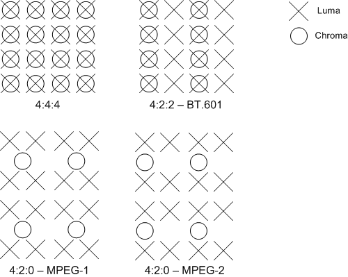
上图的 4:2:2 采样定义在 BT.601 标准中。这里还有两种 4:2:0 采样。一种用于 MPEG-2 视频。另一种用于 MPEG-1、H.261 和 H.263。
与 MPEG-1 的方案相比,MPEG-2 的方案在和 4:2:2 或 4:4:4 格式转换时更简单。MPEG-2 的方案建议在 Windows 中首选。
Surface Definitions
This section describes the 8-bit YUV formats that are recommended for video rendering. These fall into several categories:
- 4:4:4 Formats, 32 Bits per Pixel
- 4:2:2 Formats, 16 Bits per Pixel
- 4:2:0 Formats, 16 Bits per Pixel
- 4:2:0 Formats, 12 Bits per Pixel
首先,你应该了解以下概念:
- Surface origin. 对于本文中的 YUV 格式来说,原点 (0,0) 始终在左上角。
- Stride. 一个 surface 的 stride,有时也叫 pitch,是 surface 宽度的字节数。原点为左上角时,stride 始终为正。
- Alignment. 对齐由图形显示驱动决定。surface 必须始终是对齐的 DWORD;(我理解的是图像首地址必须是32的整数倍?)对齐可以大于 32 bits,这取决于硬件的需要。
- Packed 格式与 planar 格式。YUV 格式可以分为 packed 格式和 planar 格式。packed 格式中,Y,U,和 V 被存储在单个数组里。然后像素被组织成宏像素,其布局取决于具体格式。planar 格式中,Y,U 和 V 被分别存储在三个平面中(plane)。(看完就懂了)
本文中描述的每种 YUV 格式都有一个指定的 FOURCC 代码。FOURCC 代码是通过连接四个 ASCII 字符创建的32位无符号整数。
- 4:4:4 (32 bpp) (32 bits 每像素)
- 4:2:2 (16 bpp)
- 4:2:0 (16 bpp)
- 4:2:0 (12 bpp)
4:4:4 Formats, 32 Bits per Pixel
AYUV
唯一一种建议使用的 4:4:4 格式。FOURCC code AYUV。是 packed format,每个像素被编码为四个连续的字节,按下图所示的顺序存储。

字母 A 表示 alpha 通道(透明度?)。
4:2:2 Formats, 16 Bits per Pixel
有两种建议使用的 4:2:2 格式,FOURCC 码如下:
- YUY2
- UYVY
两种都是 packed formats,其中宏像素是两个像素编码成的四个连续字节。这时 chroma 色度在水平方向采样减半。
YUY2
YUY2 格式中,数组可以被视为 unsigned char 数组,第一个字节是第一个 Y 采样,第二个字节是第一个 U (Cb) 采样,第三个字节是第二个 Y 采样,第四个字节是第一个 V (Cr) 采样,如下图所示:

If the image is addressed as an array of little-endian WORD values, the first WORD contains the first Y sample in the least significant bits (LSBs) and the first U (Cb) sample in the most significant bits (MSBs). The second WORD contains the second Y sample in the LSBs and the first V (Cr) sample in the MSBs.
YUY2 是 Microsoft DirectX Video Acceleration (DirectX VA) 的首选 4:2:2 格式。It is expected to be an intermediate-term requirement for DirectX VA accelerators supporting 4:2:2 video.
UYVY
此格式与 YUY2 类似,只是字节顺序不同。下图一看就懂 the chroma and luma bytes are flipped (Figure 4). If the image is addressed as an array of two little-endian WORD values, the first WORD contains U in the LSBs and Y0 in the MSBs, and the second WORD contains V in the LSBs and Y1 in the MSBs.

4:2:0 Formats, 16 Bits per Pixel
Two 4:2:0 16-bits per pixel (bpp) formats are recommended, with the following FOURCC codes:
- IMC1
- IMC3
Both of these YUV formats are planar formats. The chroma channels are subsampled by a factor of two in both the horizontal and vertical dimensions.
IMC1
All of the Y samples appear first in memory as an array of unsigned char values. This is followed by all of the V (Cr) samples, and then all of the U (Cb) samples. The V and U planes have the same stride as the Y plane, resulting in unused areas of memory, as shown in Figure 5. The U and V planes must start on memory boundaries that are a multiple of 16 lines. Figure 5 shows the origin of U and V for a 352 x 240 video frame. The starting address of the U and V planes are calculated as follows:
syntaxCopy
BYTE* pV = pY + (((Height + 15) & ~15) * Stride);
BYTE* pU = pY + (((((Height * 3) / 2) + 15) & ~15) * Stride);
where pY is a byte pointer to the start of the memory array, as shown in the following diagram.

IMC3
This format is identical to IMC1, except the U and V planes are swapped, as shown in the following diagram.

4:2:0 Formats, 12 Bits per Pixel
Four 4:2:0 12-bpp formats are recommended, with the following FOURCC codes:
- IMC2
- IMC4
- YV12
- NV12
In all of these formats, the chroma channels are subsampled by a factor of two in both the horizontal and vertical dimensions.
IMC2
This format is the same as IMC1 except for the following difference: The V (Cr) and U (Cb) lines are interleaved at half-stride boundaries. In other words, each full-stride line in the chroma area starts with a line of V samples, followed by a line of U samples that begins at the next half-stride boundary (Figure 7). This layout makes more efficient use of address space than IMC1. It cuts the chroma address space in half, and thus the total address space by 25 percent. Among 4:2:0 formats, IMC2 is the second-most preferred format, after NV12. The following image illustrates this process.

IMC4
This format is identical to IMC2, except the U (Cb) and V (Cr) lines are swapped, as shown in the following illustration.

YV12
All of the Y samples appear first in memory as an array of unsigned char values. This array is followed immediately by all of the V (Cr) samples. The stride of the V plane is half the stride of the Y plane; and the V plane contains half as many lines as the Y plane. The V plane is followed immediately by all of the U (Cb) samples, with the same stride and number of lines as the V plane, as shown in the following illustration.

NV12
All of the Y samples appear first in memory as an array of unsigned char values with an even number of lines. The Y plane is followed immediately by an array of unsigned char values that contains packed U (Cb) and V (Cr) samples. When the combined U-V array is addressed as an array of little-endian WORD values, the LSBs contain the U values, and the MSBs contain the V values. NV12 is the preferred 4:2:0 pixel format for DirectX VA. It is expected to be an intermediate-term requirement for DirectX VA accelerators supporting 4:2:0 video. The following illustration shows the Y plane and the array that contains packed U and V samples.

Color Space and Chroma Sampling Rate Conversions
本部分介绍如何在 YUV 和 RGB 之间转换,以及如何在不同的 YUV 格式之间转换。我们在这里举例两种 RGB 格式:8-bit computer RGB,又叫 sRGB 或 "full-scale" RGB,和 studio video RGB,或 "RGB with head-room and toe-room."他们定义如下:
- Computer RGB 使用 8 bits 表示每个红、绿、蓝采样。黑色为 R = G = B = 0,白色为 R = G = B = 255。
- Studio video RGB uses some number of bits N for each sample of red, green, and blue, where N is 8 or more. Studio video RGB uses a different scaling factor than computer RGB, and it has an offset. Black is represented by R = G = B = 16*2^(N-8), and white is represented by R = G = B = 235*2^(N-8). However, actual values may fall outside this range.
Studio video RGB is the preferred RGB definition for video in Windows, while computer RGB is the preferred RGB definition for non-video applications. In either form of RGB, the chromaticity coordinates are as specified in ITU-R BT.709 for the definition of the RGB color primaries. The (x,y) coordinates of R, G, and B are (0.64, 0.33), (0.30, 0.60), and (0.15, 0.06), respectively. Reference white is D65 with coordinates (0.3127, 0.3290). Nominal gamma is 1/0.45 (approximately 2.2), with precise gamma defined in detail in ITU-R BT.709.
Conversion between RGB and 4:4:4 YUV
We first describe conversion between RGB and 4:4:4 YUV. To convert 4:2:0 or 4:2:2 YUV to RGB, we recommend converting the YUV data to 4:4:4 YUV, and then converting from 4:4:4 YUV to RGB. The AYUV format, which is a 4:4:4 format, uses 8 bits each for the Y, U, and V samples. YUV can also be defined using more than 8 bits per sample for some applications.
Two dominant YUV conversions from RGB have been defined for digital video. Both are based on the specification known as ITU-R Recommendation BT.709. The first conversion is the older YUV form defined for 50-Hz use in BT.709. It is the same as the relation specified in ITU-R Recommendation BT.601, also known by its older name, CCIR 601. It should be considered the preferred YUV format for standard-definition TV resolution (720 x 576) and lower-resolution video. It is characterized by the values of two constants Kr and Kb:
syntaxCopy
Kr = 0.299
Kb = 0.114
The second conversion is the newer YUV form defined for 60-Hz use in BT.709, and should be considered the preferred format for video resolutions above SDTV. It is characterized by different values for these two constants:
syntaxCopy
Kr = 0.2126
Kb = 0.0722
Conversion from RGB to YUV is defined by starting with the following:
syntaxCopy
L = Kr * R + Kb * B + (1 - Kr - Kb) * G
The YUV values are then obtained as follows:
syntaxCopy
Y =                   floor(2^(M-8) * (219*(L-Z)/S + 16) + 0.5)
U = clip3(0, (2^M)-1, floor(2^(M-8) * (112*(B-L) / ((1-Kb)*S) + 128) + 0.5))
V = clip3(0, (2^M)-1, floor(2^(M-8) * (112*(R-L) / ((1-Kr)*S) + 128) + 0.5))
where
- M is the number of bits per YUV sample (M >= 8).
- Z is the black-level variable. For computer RGB, Z equals 0. For studio video RGB, Z equals 16*2^(N-8), where N is the number of bits per RGB sample (N >= 8).
- S is the scaling variable. For computer RGB, S equals 255. For studio video RGB, S equals 219*2^(N-8).
The function floor(x) returns the largest integer less than or equal to x. The function clip3(x, y, z) is defined as follows:
syntaxCopy
clip3(x, y, z) = ((z < x) ? x : ((z > y) ? y : z))
Note
clip3 should be implemented as a function rather than a preprocessor macro; otherwise multiple evaluations of the arguments will occur.
The Y sample represents brightness, and the U and V samples represent the color deviations toward blue and red, respectively. The nominal range for Y is 16*2^(M-8) to 235*2^(M-8). Black is represented as 16*2^(M-8), and white is represented as 235*2^(M-8). The nominal range for U and V are 16*2^(M-8) to 240*2^(M-8), with the value 128*2^(M-8) representing neutral chroma. However, actual values may fall outside these ranges.
For input data in the form of studio video RGB, the clip operation is necessary to keep the U and V values within the range 0 to (2^M)-1. If the input is computer RGB, the clip operation is not required, because the conversion formula cannot produce values outside of this range.
These are the exact formulas without approximation. Everything that follows in this document is derived from these formulas. This section describes the following conversions:
- Converting RGB888 to YUV 4:4:4
- Converting 8-bit YUV to RGB888
- Converting 4:2:0 YUV to 4:2:2 YUV
- Converting 4:2:2 YUV to 4:4:4 YUV
- Converting 4:2:0 YUV to 4:4:4 YUV
Converting RGB888 to YUV 4:4:4
In the case of computer RGB input and 8-bit BT.601 YUV output, we believe that the formulas given in the previous section can be reasonably approximated by the following:
syntaxCopy
Y = ( (  66 * R + 129 * G +  25 * B + 128) >> 8) +  16
U = ( ( -38 * R -  74 * G + 112 * B + 128) >> 8) + 128
V = ( ( 112 * R -  94 * G -  18 * B + 128) >> 8) + 128
These formulas produce 8-bit results using coefficients that require no more than 8 bits of (unsigned) precision. Intermediate results will require up to 16 bits of precision.
Converting 8-bit YUV to RGB888
From the original RGB-to-YUV formulas, one can derive the following relationships for BT.601.
syntaxCopy
Y = round( 0.256788 * R + 0.504129 * G + 0.097906 * B) +  16
U = round(-0.148223 * R - 0.290993 * G + 0.439216 * B) + 128
V = round( 0.439216 * R - 0.367788 * G - 0.071427 * B) + 128
Therefore, given:
syntaxCopy
C = Y - 16
D = U - 128
E = V - 128
the formulas to convert YUV to RGB can be derived as follows:
syntaxCopy
R = clip( round( 1.164383 * C                   + 1.596027 * E  ) )
G = clip( round( 1.164383 * C - (0.391762 * D) - (0.812968 * E) ) )
B = clip( round( 1.164383 * C +  2.017232 * D                   ) )
where clip() denotes clipping to a range of [0..255]. We believe these formulas can be reasonably approximated by the following:
syntaxCopy
R = clip(( 298 * C           + 409 * E + 128) >> 8)
G = clip(( 298 * C - 100 * D - 208 * E + 128) >> 8)
B = clip(( 298 * C + 516 * D           + 128) >> 8)
These formulas use some coefficients that require more than 8 bits of precision to produce each 8-bit result, and intermediate results will require more than 16 bits of precision.
To convert 4:2:0 or 4:2:2 YUV to RGB, we recommend converting the YUV data to 4:4:4 YUV, and then converting from 4:4:4 YUV to RGB. The sections that follow present some methods for converting 4:2:0 and 4:2:2 formats to 4:4:4.
Converting 4:2:0 YUV to 4:2:2 YUV
Converting 4:2:0 YUV to 4:2:2 YUV requires vertical upconversion by a factor of two. This section describes an example method for performing the upconversion. The method assumes that the video pictures are progressive scan.
Note
The 4:2:0 to 4:2:2 interlaced scan conversion process presents atypical problems and is difficult to implement. This article does not address the issue of converting interlaced scan from 4:2:0 to 4:2:2.
Let each vertical line of input chroma samples be an array Cin[] that ranges from 0 to N - 1. The corresponding vertical line on the output image will be an array Cout[] that ranges from 0 to 2N - 1. To convert each vertical line, perform the following process:
syntaxCopy
Cout[0]     = Cin[0];
Cout[1]     = clip((9 * (Cin[0] + Cin[1]) - (Cin[0] + Cin[2]) + 8) >> 4);
Cout[2]     = Cin[1];
Cout[3]     = clip((9 * (Cin[1] + Cin[2]) - (Cin[0] + Cin[3]) + 8) >> 4);
Cout[4]     = Cin[2]
Cout[5]     = clip((9 * (Cin[2] + Cin[3]) - (Cin[1] + Cin[4]) + 8) >> 4);
...
Cout[2*i]   = Cin[i]
Cout[2*i+1] = clip((9 * (Cin[i] + Cin[i+1]) - (Cin[i-1] + Cin[i+2]) + 8) >> 4);
...
Cout[2*N-3] = clip((9 * (Cin[N-2] + Cin[N-1]) - (Cin[N-3] + Cin[N-1]) + 8) >> 4);
Cout[2*N-2] = Cin[N-1];
Cout[2*N-1] = clip((9 * (Cin[N-1] + Cin[N-1]) - (Cin[N-2] + Cin[N-1]) + 8) >> 4);
where clip() denotes clipping to a range of [0..255].
Note
The equations for handling the edges can be mathematically simplified. They are shown in this form to illustrate the clamping effect at the edges of the picture.
In effect, this method calculates each missing value by interpolating the curve over the four adjacent pixels, weighted toward the values of the two nearest pixels (Figure 11). The specific interpolation method used in this example generates missing samples at half-integer positions using a well-known method called Catmull-Rom interpolation, also known as cubic convolution interpolation.

In signal processing terms, the vertical upconversion should ideally include a phase shift compensation to account for the half-pixel vertical offset (relative to the output 4:2:2 sampling grid) between the locations of the 4:2:0 sample lines and the location of every other 4:2:2 sample line. However, introducing this offset would increase the amount of processing required to generate the samples, and make it impossible to reconstruct the original 4:2:0 samples from the upsampled 4:2:2 image. It would also make it impossible to decode video directly into 4:2:2 surfaces and then use those surfaces as reference pictures for decoding subsequent pictures in the stream. Therefore, the method provided here does not take into account the precise vertical alignment of the samples. Doing so is probably not visually harmful at reasonably high picture resolutions.
If you start with 4:2:0 video that uses the sampling grid defined in H.261, H.263, or MPEG-1 video, the phase of the output 4:2:2 chroma samples will also be shifted by a half-pixel horizontal offset relative to the spacing on the luma sampling grid (a quarter-pixel offset relative to the spacing of the 4:2:2 chroma sampling grid). However, the MPEG-2 form of 4:2:0 video is probably more commonly used on PCs and does not suffer from this problem. Moreover, the distinction is probably not visually harmful at reasonably high picture resolutions. Trying to correct for this problem would create the same sort of problems discussed for the vertical phase offset.
Converting 4:2:2 YUV to 4:4:4 YUV
Converting 4:2:2 YUV to 4:4:4 YUV requires horizontal upconversion by a factor of two. The method described previously for vertical upconversion can also be applied to horizontal upconversion. For MPEG-2 and ITU-R BT.601 video, this method will produce samples with the correct phase alignment.
Converting 4:2:0 YUV to 4:4:4 YUV
To convert 4:2:0 YUV to 4:4:4 YUV, you can simply follow the two methods described previously. Convert the 4:2:0 image to 4:2:2, and then convert the 4:2:2 image to 4:4:4. You can also switch the order of the two upconversion processes, as the order of operation does not really matter to the visual quality of the result.
Other YUV Formats
Some other, less common YUV formats include the following:
- AI44 is a palettized YUV format with 8 bits per sample. Each sample contains an index in the 4 most significant bits (MSBs) and an alpha value in the 4 least significant bits (LSBs). The index refers to an array of YUV palette entries, which must be defined in the media type for the format. This format is primarily used for subpicture images.
- NV11 is a 4:1:1 planar format with 12 bits per pixel. The Y samples appear first in memory. The Y plane is followed by an array of packed U (Cb) and V (Cr) samples. When the combined U-V array is addressed as an array of little-endian WORD values, the U samples are contained in the LSBs of each WORD, and the V samples are contained in the MSBs. (This memory layout is similar to NV12 although the chroma sampling is different.)
- Y41P is a 4:1:1 packed format, with U and V sampled every fourth pixel horizontally. Each macropixel contains 8 pixels in three bytes, with the following byte layout:
U0 Y0 V0 Y1 U4 Y2 V4 Y3 Y4 Y5 Y6 Y7 - Y41T is identical to Y41P, except the least-significant bit of each Y sample specifies the chroma key (0 = transparent, 1 = opaque).
- Y42T is identical to UYVY, except the least-significant bit of each Y sample specifies the chroma key (0 = transparent, 1 = opaque).
- YVYU is equivalent to YUYV except the U and V samples are swapped.
Identifying YUV Formats in Media Foundation
Each of the YUV formats described in this article has an assigned FOURCC code. A FOURCC code is a 32-bit unsigned integer that is created by concatenating four ASCII characters.
There are various C/C++ macros that make it easier to declare FOURCC values in source code. For example, the MAKEFOURCC macro is declared in Mmsystem.h, and the FCC macro is declared in Aviriff.h. Use them as follows:
DWORD fccYUY2 = MAKEFOURCC('Y','U','Y','2');
DWORD fccYUY2 = FCC('YUY2');
You can also declare a FOURCC code directly as a string literal simply by reversing the order of the characters. For example:
DWORD fccYUY2 = '2YUY'; // Declares the FOURCC 'YUY2'
Reversing the order is necessary because the Windows operating system uses a little-endian architecture. 'Y' = 0x59, 'U' = 0x55, and '2' = 0x32, so '2YUY' is 0x32595559.
In Media Foundation, formats are identified by a major type GUID and a subtype GUID. The major type for computer video formats is always MFMediaType_Video . The subtype can be constructed by mapping the FOURCC code to a GUID, as follows:
XXXXXXXX-0000-0010-8000-00AA00389B71
where XXXXXXXX is the FOURCC code. Thus, the subtype GUID for YUY2 is:
32595559-0000-0010-8000-00AA00389B71
Constants for the most common YUV format GUIDs are defined in the header file mfapi.h. For a list of these constants, see Video Subtype GUIDs.


 686
686

 被折叠的 条评论
为什么被折叠?
被折叠的 条评论
为什么被折叠?
 到【灌水乐园】发言


