


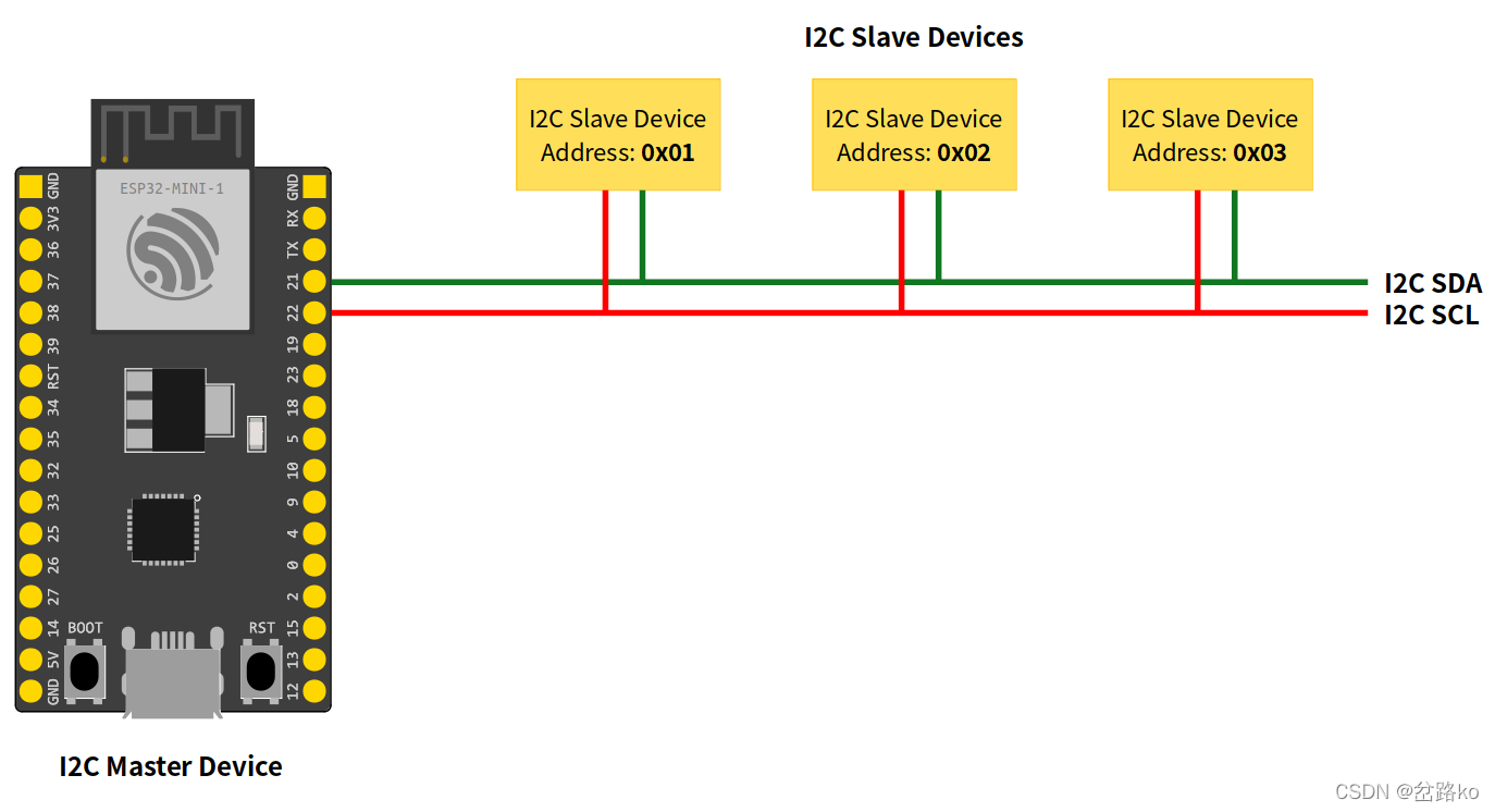
一、I2C简介
I2C协议涉及使用两条线路来发送和接收数据:Arduino控制器板定期脉冲的串行时钟引脚(SCL)和串行数据引脚(SDA),用于在两个器件之间发送数据。当时钟线从低电平变为高电平(称为时钟脉冲的上升沿)时,一个信息位(将按顺序形成特定器件的地址和命令或数据)通过SDA线从电路板传输到I2C器件。当这些信息被逐位发送时,被调用的设备执行请求,并在需要时使用控制器在SCL上仍然生成的时钟信号作为定时,通过同一条线路将其数据发送回电路板。
由于I2C协议允许每个启用的设备都有自己唯一的地址,并且作为控制器和外围设备轮流通过单条线路进行通信,因此Arduino板可以与许多设备或其他板进行通信(反过来),同时仅使用微控制器的两个引脚。
二、ESP32 I2C 脚位
默认引脚可能因主板而异。在通用 ESP32 上,默认的 I2C 引脚为:
亲测可用脚位:1,2,3,4,5,6,7,8,9,10,18,19
SDA: GPIO8
SCL: GPIO9


#ifndef Pins_Arduino_h
#define Pins_Arduino_h

#include <stdint.h>

#define EXTERNAL_NUM_INTERRUPTS 22
#define NUM_DIGITAL_PINS        22
#define NUM_ANALOG_INPUTS       6

#define analogInputToDigitalPin(p)  (((p)<NUM_ANALOG_INPUTS)?(esp32_adc2gpio[(p)]):-1)
#define digitalPinToInterrupt(p)    (((p)<NUM_DIGITAL_PINS)?(p):-1)
#define digitalPinHasPWM(p)         (p < EXTERNAL_NUM_INTERRUPTS)

static const uint8_t TX = 21;
static const uint8_t RX = 20;

static const uint8_t SDA = 8;
static const uint8_t SCL = 9;

static const uint8_t SS    = 7;
static const uint8_t MOSI  = 6;
static const uint8_t MISO  = 5;
static const uint8_t SCK   = 4;

static const uint8_t A0 = 0;
static const uint8_t A1 = 1;
static const uint8_t A2 = 2;
static const uint8_t A3 = 3;
static const uint8_t A4 = 4;
static const uint8_t A5 = 5;

#endif /* Pins_Arduino_h */
三、ICO工作模式
主控模式:在此模式下,ESP32 生成时钟信号并启动与从设备之间的通信。
从模式在从模式中,时钟由主设备生成,如果目标地址与目标地址相同,则响应主设备。
四、I2C 类库介绍
使用此库 WireMaster.ino 主设备模式
#include "Wire.h"
#define I2C_DEV_ADDR 0x55
uint32_t i = 0;
void setup() {
  Serial.begin(115200);
  Serial.setDebugOutput(true);
  Wire.begin();
}

void loop() {
  delay(5000);
  //Write message to the slave
  Wire.beginTransmission(I2C_DEV_ADDR);
  Wire.printf("Hello World! %u", i++);
  uint8_t error = Wire.endTransmission(true);
  Serial.printf("endTransmission: %u\n", error);
  //Read 16 bytes from the slave
  error = Wire.requestFrom(I2C_DEV_ADDR, 16);
  Serial.printf("requestFrom: %u\n", error);
  if(error){
    uint8_t temp[error];
    Wire.readBytes(temp, error);
    log_print_buf(temp, error);
  }
}
WireSlave.ino从设备模式
#include "Wire.h"

#define I2C_DEV_ADDR 0x55
uint32_t i = 0;
void onRequest(){
  Wire.print(i++);
  Wire.print(" Packets.");
  Serial.println("onRequest");
}

void onReceive(int len){
  Serial.printf("onReceive[%d]: ", len);
  while(Wire.available()){
    Serial.write(Wire.read());
  }
  Serial.println();
}

void setup() {
  Serial.begin(115200);
  Serial.setDebugOutput(true);
  Wire.onReceive(onReceive);
  Wire.onRequest(onRequest);
  Wire.begin((uint8_t)I2C_DEV_ADDR);

#if CONFIG_IDF_TARGET_ESP32
  char message[64];
  snprintf(message, 64, "%u Packets.", i++);
  Wire.slaveWrite((uint8_t *)message, strlen(message));
#endif
}

void loop() {

}
五、方法介绍
具体信息可以查看这个链接
https://docs.espressif.com/projects/arduino-esp32/en/latest/api/i2c.html
begin 此功能用于启动外围设备,使用默认配置。
setPins此函数用于定义和引脚。SDA SCL,需要在begin之前调用。 此方法需要在begin后调用
setClock使用此函数设置总线时钟。如果不使用此功能,将使用此默认值。
getClock获取总线时钟数值。
六、备注
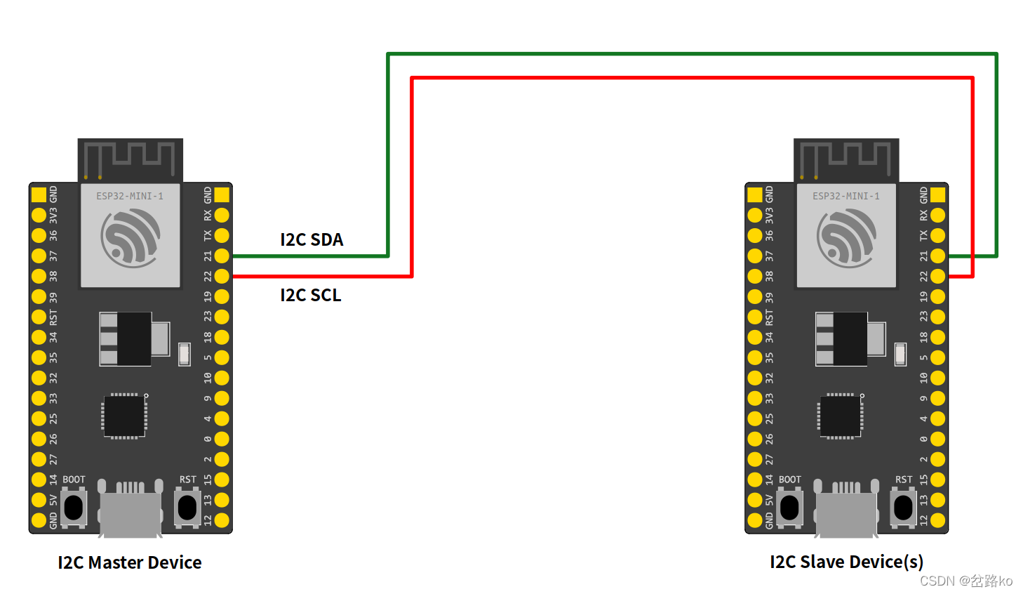
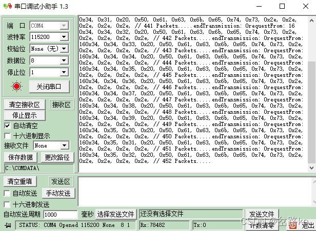
需要使用两块 ESP32-C3 开发板, 用杜邦线 使 两块板子的8脚相连,9脚相连,串口调试助手效果图。


 364
364

 被折叠的 条评论
为什么被折叠?
被折叠的 条评论
为什么被折叠?
 到【灌水乐园】发言


