


4.1 Preliminaries
The Direct3D initialization process requires us to be familiar with some basic graphics concepts and Direct3D types. We introduce these ideas and types in this section, so that we do not have to digress in the next section.
4.1.1 Direct3D Overview
Direct3D is a low-level graphics API (application programming interface) that enables us to render 3D worlds using 3D hardware acceleration. Essentially, Direct3D provides the software interfaces through which we control the graphics hardware. For example, to instruct the graphics device to clear the render target (e.g., the screen), we would call the Direct3D method ID3D10Device::ClearRenderTargetView. Having the Direct3D layer between the application and the graphics hardware means we do not have to worry about the specifics of the 3D hardware, so long as it is a Direct3D 10-capable device.
A Direct3D 10-capable graphics device must support the entire Direct3D 10 capability set, with few exceptions (some things like the multisampling count still need to be queried). This is in contrast to Direct3D 9, where a device only had to support a subset of Direct3D 9 capabilities; consequently, if a Direct3D 9 application wanted to use a certain feature, it was necessary to first check if the available hardware supported that feature, as calling a Direct3D function not implemented by the hardware resulted in failure. In Direct3D 10, device capability checking is no longer necessary since it is now a strict requirement that a Direct3D 10 device implement the entire Direct3D 10 capability set.
4.1.2 COM
Component Object Model (COM) is the technology that allows DirectX to be programming language independent and have backward compatibility. We usually refer to a COM object as an interface, which for our purposes can be thought of and used as a C++ class. Most of the details of COM are hidden to us when programming DirectX with C++. The only thing that we must know is that we obtain pointers to COM interfaces through special functions or by the methods of another COM interface — we do not create a COM interface with the C++ new keyword. In addition, when we are done with an interface we call its Release method (all COM interfaces inherit functionality from the IUnknown COM interface, which provides the Release method) rather than delete it — COM objects perform their own memory management.
There is, of course, much more to COM, but more detail is not necessary for using DirectX effectively.
| Note | COM interfaces are prefixed with a capital I. For example, the COM interface that represents a 2D texture is called ID3D10Texture2D. |
4.1.3 Textures and Data Resource Formats
A 2D texture is a matrix of data elements. One use for 2D textures is to store 2D image data, where each element in the texture stores the color of a pixel. However, this is not the only usage; for example, in an advanced technique called normal mapping, each element in the texture stores a 3D vector instead of a color. Therefore, although it is common to think of textures as storing image data, they are really more general purpose than that. A 1D texture is like a 1D array of data elements, and a 3D texture is like a 3D array of data elements. As will be discussed in later chapters, textures are more than just arrays of data; they can have mipmap levels, and the GPU can do special operations on them, such as applying filters and multisampling. In addition, a texture cannot store arbitrary kinds of data; it can only store certain kinds of data formats, which are described by the DXGI_FORMAT enumerated type. Some example for mats are:
-
DXGI_FORMAT_R32G32B32_FLOAT: Each element has three 32-bit floating-point components.
-
DXGI_FORMAT_R16G16B16A16_UNORM: Each element has four 16-bit components mapped to the [0, 1] range.
-
DXGI_FORMAT_R32G32_UINT: Each element has two 32-bit unsigned integer components.
-
DXGI_FORMAT_R8G8B8A8_UNORM: Each element has four 8-bit unsigned components mapped to the [0, 1] range.
-
DXGI_FORMAT_R8G8B8A8_SNORM: Each element has four 8-bit signed components mapped to the [−1, 1] range.
-
DXGI_FORMAT_R8G8B8A8_SINT: Each element has four 8-bit signed integer components mapped to the [−128, 127] range.
-
DXGI_FORMAT_R8G8B8A8_UINT: Each element has four 8-bit unsigned integer components mapped to the [0, 255] range.
Note that the R, G, B, A letters are used to stand for red, green, blue, and alpha, respectively. Colors are formed as combinations of the basis colors red, green, and blue (e.g., equal values of red and green make yellow). The alpha channel or alpha component is generally used to control transparency. However, as we said earlier, textures need not store color information; for example, the format
DXGI_FORMAT_R32G32B32_FLOAT
has three floating-point components and can therefore store a 3D vector with floating-point coordinates. There are also typeless formats, where we just reserve memory and then specify how to reinterpret the data at a later time (sort of like a cast) when the texture is bound to the pipeline; for example, the following typeless format reserves elements with four 8-bit components, but does not specify the data type (e.g., integer, floating-point, unsigned integer):
DXGI_FORMAT_R8G8B8A8_TYPELESS
4.1.4 The Swap Chain and Page Flipping
To avoid flickering in animation, it is best to draw a frame of animation into an off-screen texture called the back buffer. Once the entire scene has been drawn to the back buffer for the given frame of animation, it is presented to the screen as one complete frame; in this way, the viewer does not watch as the frame gets drawn — the viewer only sees complete frames. The ideal time to present the frame to the screen is during the vertical blanking interval. To implement this, two texture buffers are maintained by the hardware, one called the front buffer and a second called the back buffer. The front buffer stores the image data currently being displayed on the monitor, while the next frame of animation is being drawn to the back buffer. After the frame has been drawn to the back buffer, the roles of the back buffer and front buffer are reversed: The back buffer becomes the front buffer and the front buffer becomes the back buffer for the next frame of animation. Swapping the roles of the back and front buffers is called presenting. Presenting is an efficient operation, as the pointer to the current front buffer and the pointer to the current back buffer just need to be swapped. Figure 4.1 illustrates the process.
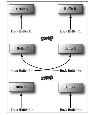
Figure 4.1: We first render to Buffer B, which is serving as the current back buffer. Once the frame is completed, the pointers are swapped and Buffer B becomes the front buffer and Buffer A becomes the new back buffer. We then render the next frame to Buffer A. Once the frame is completed, the pointers are swapped and Buffer A becomes the front buffer and Buffer B becomes the back buffer again.
The front and back buffer form a swap chain. In Direct3D, a swap chain is represented by the IDXGISwapChain interface. This interface stores the front and back buffer textures, as well as provides methods for resizing the buffers (IDXGISwapChain::ResizeBuffers) and presenting (IDXGISwapChain::Present). We will discuss these methods in detail in §4.5.
Using two buffers (front and back) is called double buffering. More than two buffers can be employed; using three buffers is called triple buffering. Two buffers are usually sufficient, however.
| Note | Even though the back buffer is a texture (so an element should be called a texel), we often call an element a pixel since, in the case of the back buffer, it stores color information. Sometimes people will call an element of a texture a pixel, even if it doesn’t store color information (e.g., “the pixels of a normal map”). |
4.1.5 Depth Buffering
The depth buffer is an example of a texture that does not contain image data, but rather depth information about a particular pixel. The possible depth values range from 0.0 to 1.0, where 0.0 denotes the closest an object can be to the viewer and 1.0 denotes the farthest an object can be from the viewer. There is a one-to-one correspondence between each element in the depth buffer and each pixel in the back buffer (i.e., the ijth element in the back buffer corresponds to the ijth element in the depth buffer). So if the back buffer had a resolution of 1280×1024, there would be 1280×1024 depth entries.
Figure 4.2 shows a simple scene where some objects partially obscure the objects behind them. In order for Direct3D to determine which pixels of an object are in front of another, it uses a technique called depth buffering or z-buffering. Let us emphasize that with depth buffering, the order in which we draw the objects does not matter.

| Remark | To handle the depth problem, one might suggest drawing the objects in the scene in the order of farthest to nearest. In this way, near objects will be painted over far objects, and the correct results should be rendered. This is how a painter would draw a scene. However, this method has its own problems — sorting a large data set and intersecting geometry. Besides, the graphics hardware gives us depth buffering for free. |
To illustrate how depth buffering works, let’s look at an example. Consider Figure 4.3, which shows the volume the viewer sees (left) and a 2D side view of that volume (right). From the figure, we observe that three different pixels compete to be rendered onto the pixel P on the view window. (Of course, we know the closest pixel should be rendered to P since it obscures the ones behind it, but the computer does not.) First, before any rendering takes place, the back buffer is cleared to a default color (like black or white), and the depth buffer is cleared to a default value — usually 1.0 (the farthest depth value a pixel can have). Now, suppose that the objects are rendered in the order of cylinder, sphere, and cone. The following table summarizes how the pixel P and its corresponding depth value are updated as the objects are drawn; a similar process happens for the other pixels.
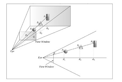
Figure 4.3: The view window corresponds to the 2D image (back buffer) we generate of the 3D scene. We see that three different pixels can be projected to the pixel P. Intuition tells us that P1 should be written to P since it is closer to the viewer and blocks the other two pixels. The depth buffer algorithm provides a mechanical procedure for determining this on a computer. Note that we show the depth values relative to the 3D scene being viewed, but they are actually normalized to the range [0.0, 1.0] when stored in the depth buffer.
| Operation | P | d | Description |
|---|---|---|---|
| Clear operation | Black | 1.0 | Pixel and corresponding depth entry initialized. |
| Draw cylinder | P3 | d3 | Since d3≤ d = 1.0, the depth test passes and we update the buffers by setting P = P3 and d = d3. |
| Draw sphere | P1 | d1 | Since d1≤ d = d3, the depth test passes and we update the buffers by setting P = P1 and d = d1. |
| Draw cone | P1 | d1 | Since d2 > d = d1, the depth test fails and we do not update the buffers. |
As you can see, we only update the pixel and its corresponding depth value in the depth buffer when we find a pixel with a smaller depth value. In this way, after all is said and done, the pixel that is closest to the viewer will be the one rendered. (You can try switching the drawing order around and working through this example again if you are still not convinced.)
To summarize, depth buffering works by computing a depth value for each pixel and performing a depth test. The depth test compares the depths of pixels competing to be written to a particular pixel location on the back buffer. The pixel with the depth value closest to the viewer wins, and that is the pixel that gets written to the back buffer. This makes sense because the pixel closest to the viewer obscures the pixels behind it.
The depth buffer is a texture, so it must be created with certain data formats. The formats used for depth buffering are as follows:
-
DXGI_FORMAT_D32_FLOAT_S8X24_UINT: Specifies a 32-bit floating-point depth buffer, with 8 bits (unsigned integer) reserved for the stencil buffer mapped to the [0, 255] range and 24 bits used for padding.
-
DXGI_FORMAT_D32_FLOAT: Specifies a 32-bit floating-point depth buffer.
-
DXGI_FORMAT_D24_UNORM_S8_UINT: Specifies an unsigned 24-bit depth buffer mapped to the [0, 1] range with 8 bits (unsigned integer) reserved for the stencil buffer mapped to the [0, 255] range.
-
DXGI_FORMAT_D16_UNORM: Specifies an unsigned 16-bit depth buffer mapped to the [0, 1] range.
| Note | An application is not required to have a stencil buffer, but if it does, the stencil buffer is always attached to the depth buffer. For example, the 32-bit format DXGI_FORMAT_D24_UNORM_S8_UINT uses 24 bits for the depth buffer and 8 bits for the stencil buffer. For this reason, the depth buffer is better called the depth/stencil buffer. Using the stencil buffer is a more advanced topic and will be explained in Chapter 9. |
4.1.6 Texture Resource Views
A texture can be bound to different stages of the rendering pipeline; for example, it is common to use a texture as a render target (i.e., Direct3D draws into the texture) and as a shader resource (i.e., the texture will be sampled in a shader). A texture resource created for these two purposes would be given the bind flags:
D3D10_BIND_RENDER_TARGET | D3D10_BIND_SHADER_RESOURCE
indicating the two pipeline stages the texture will be bound to. Actually, resources are not directly bound to a pipeline stage; instead, their associated resource views are bound to different pipeline stages. For each way we wish to use a texture, Direct3D requires that we create a resource view of that texture at initialization time. This is mostly for efficiency, as the SDK documentation points out: “This allows validation and mapping in the runtime and driver to occur at view creation, minimizing type checking at bind time.” So for the example of using a texture as a render target and shader resource, we would need to create two views: a render target view (ID3D10RenderTargetView) and a shader resource view (ID3D10ShaderResourceView). Resource views essentially do two things: They tell Direct3D how the resource will be used (i.e., what stage of the pipeline you will bind it to), and if the resource format was specified as typeless at creation time, then we must now state the type when creating a view. Thus, with typeless formats, it is possible for the elements of a texture to be viewed as floating-point values in one pipeline stage and as integers in another.
In order to create a specific view to a resource, the resource must be created with that specific bind flag. For instance, if the resource was not created with the D3D10_BIND_DEPTH_STENCIL bind flag (which indicates the texture will be bound to the pipeline as a depth/stencil buffer), then we cannot create an ID3D10DepthStencilView to that resource. If you try, you should get a Direct3D debug error like the following:
ERROR: ID3D10Device::CreateDepthStencilView: A DepthStencilViewcannot be created of a Resource that did not specifyD3D10_BIND_DEPTH_STENCIL.
We will have a chance to see code for creating a render target view and a depth/stencil view in §4.2 of this chapter. Creating a shader resource view will be seen in Chapter 7. Using a texture as a render target and shader resource will come much later in this book.
| Note | The August 2007 SDK documentation says: “Creating a fully-typed resource restricts the resource to the format it was created with. This enables the runtime to optimize access ….” Therefore, you should only create a typeless resource if you really need it; otherwise, create a fully typed resource. |
4.1.7 Multisampling
Because the pixels on a monitor are not infinitely small, an arbitrary line cannot be represented perfectly on the computer monitor. The upper line in Figure 4.4 illustrates a “stairstep” (aliasing) effect, which can occur when approximating a line by a matrix of pixels.
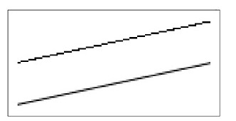
Figure 4.4: On the top we observe aliasing (the stairstep effect when trying to represent a line by a matrix of pixels). On the bottom, we see an antialiased line, which generates the final color of a pixel by sampling and using its neighboring pixels; this results in a smoother image and dilutes the stairstep effect.
Shrinking the pixel sizes by increasing the monitor resolution can alleviate the problem significantly to where the stairstep effect goes largely unnoticed.
When increasing the monitor resolution is not possible or not enough, we can apply antialiasing techniques. Direct3D supports an antialiasing technique called multisampling, which works by taking the neighboring pixels into consideration when computing the final color of a pixel. Thus, the technique is called multisampling because it uses multiple pixel samples to compute the final color of a pixel.
In the next section, we will be required to fill out a DXGI_SAMPLE_DESC structure. This structure has two members and is defined as follows:
2 DXGI_FORMAT Format, UINT SampleCount, UINT * pNumQualityLevels);
In the demos of this book, we do not use multisampling. To indicate this, we set the sample count to 1 and the quality level to 0.
| Note | A DXGI_SAMPLE_DESC structure needs to be filled out for both the swap chain buffer and the depth buffer. Both the back buffer and depth buffer must be created with the same multisampling settings; sample code illustrating this is given in the next section. |
2 UINT Count;
3 UINT Quality;
4 } DXGI_SAMPLE_DESC, * LPDXGI_SAMPLE_DESC;


 1254
1254

 被折叠的 条评论
为什么被折叠?
被折叠的 条评论
为什么被折叠?
 到【灌水乐园】发言


