


为什么要做极线校正?
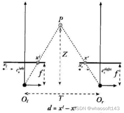
三维重建是通过双目立体匹配实现的如图1,通过匹配空间中点在两个图像中的投影点,再根据三角关系得到P的Z值。

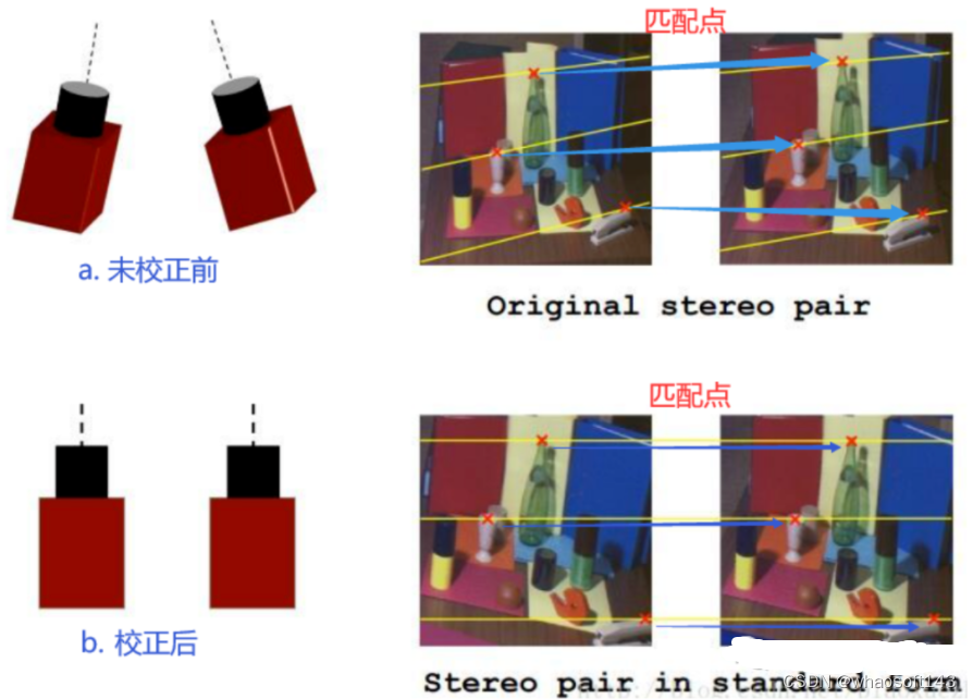
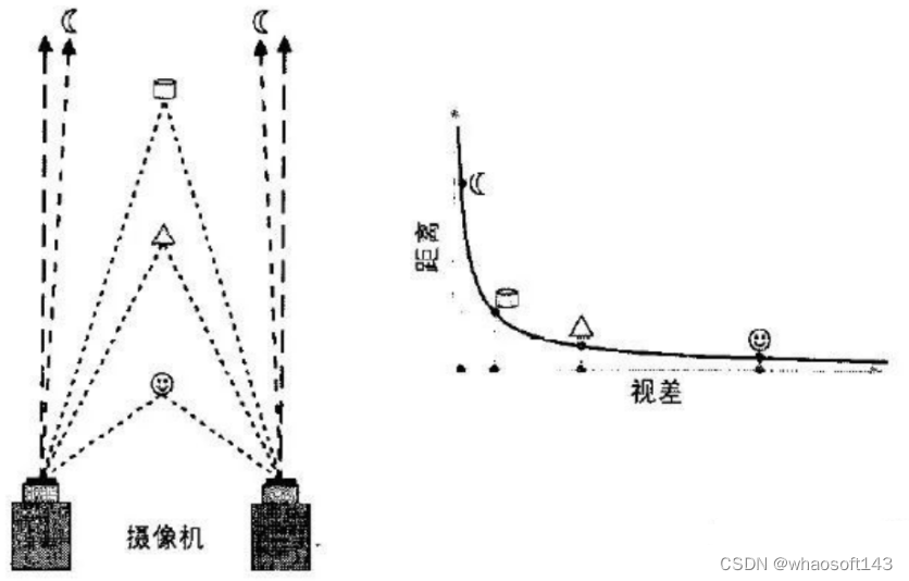
我们双目相机拍摄的时候实际情况下如下图a,两个图像做匹配时如我们图中蓝色箭头指示的匹配点那样,需要在全图中进行查找。但是如果我们对相机进行校正,使得它们成像面平行且行对齐如下图b,匹配点在同一行。那么我们只需在同行上查找,大大节约时间。因此,极线校正目的是对两幅图像的二维匹配搜索变成一维,节省计算量,排除虚假匹配点。
做极线校正我们需要知道哪些基础的立体视觉相关的基础知识?
1. 齐次坐标,刚体变换
- 齐次坐标
用n+1维矢量表示n维矢量,主要用途是可以方便矩阵运算。(参考下式)
- 刚体变换
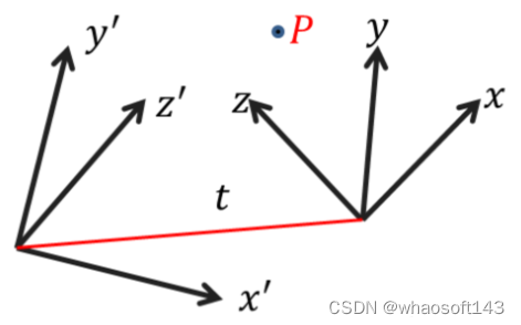
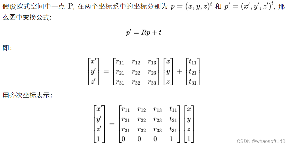
刚性物体无论位置和方向发生变换还是在不同坐标系下观察同一个物体,它的形状和大小都保持不变;
- 3个旋转3个平移共6个自由度;
- 用途:
- 计算一个刚体经过旋转和平移后的新坐标 ;
- 计算同一刚体在不同坐标系下的坐标。
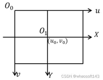
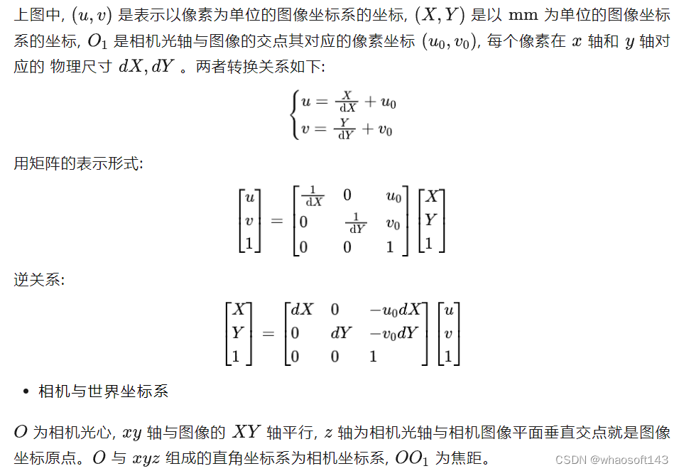
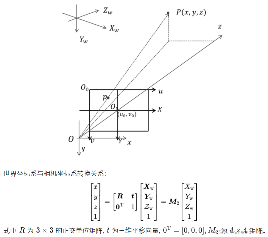
2.图像坐标系,相机坐标系,世界坐标系
- 图像坐标系
3.相机投影模型(针孔投影模型)
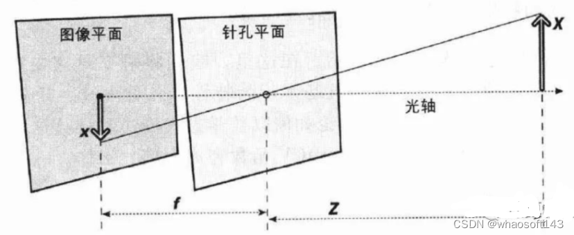
把图像平面放到针孔前方(数学上等价,计算更简单):
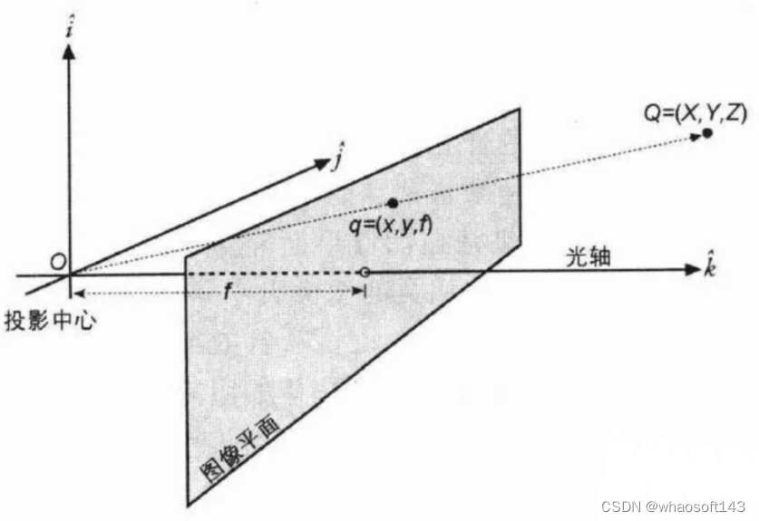
当已知图像点p时,由针孔成像模型,任何位于射线OP上的空间点的图像点都是p点,因此空间点不是唯一确定的。
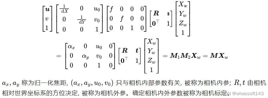
- 投影关系 (从世界坐标系到图像坐标系)
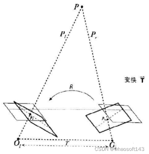
4.对极几何
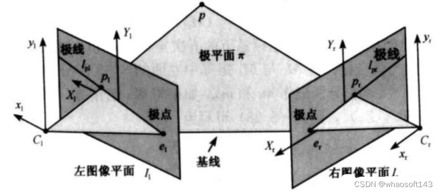
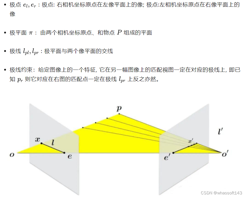
极线约束给出了对应点重要的约束条件,它将对应点匹配从整幅图像中查找压缩到一条线上查找,大大减小了搜索范围,对对应点的匹配起指导作用。
极限校正怎么实现?
1.三角测量原理
假设我们两台摄像机像平面精准位于同一平面上,且行对齐,两个光轴严格平行。
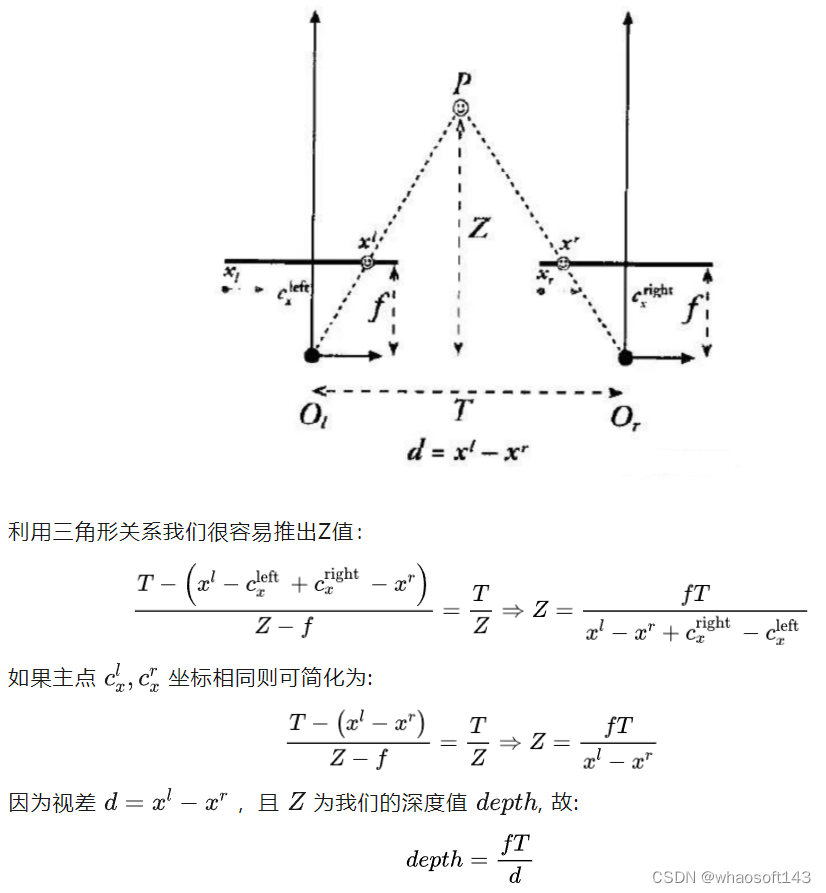
- 视差与深度图关系:
- 视差与深度成反比,视差接近0时,微小的视差变化会产生较大的深度变化
- 当视差较大时,微小的视差变化几乎不会引起深度多大的变化
- 因此,立体视觉系统仅物体距离相机较近时具有较高的深度精度
2.极线校正原理
校正过程:将相机在数学上对准到同一观察平面上,使得相机上像素行是严格对齐的
校正目的:对两幅图像的二维匹配搜索变成一维,节省计算量,排除虚假匹配点
3.校正算法步骤:(参考文献A compact algorithm for rectification of stereo pairs)

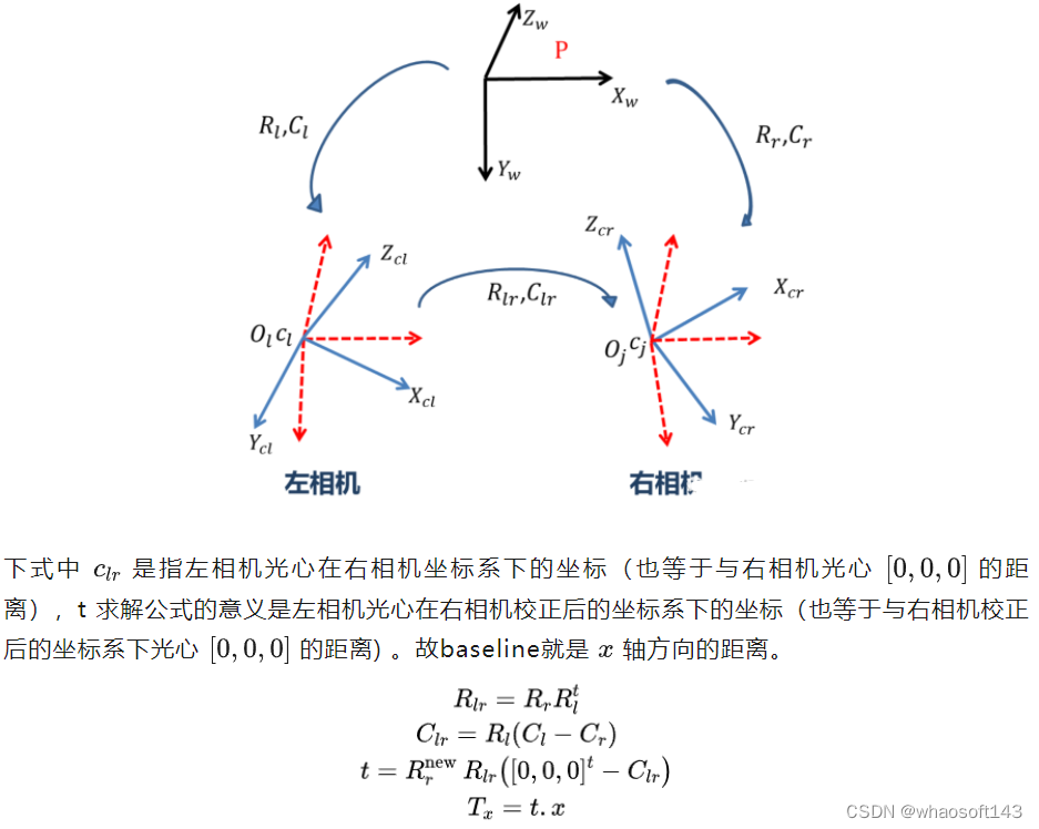
4.校正后,baseline 计算:
极线校正代码怎么写?
// see: "A compact algorithm for rectification of stereo pairs", A. Fusiello, E. Trucco, and A. Verri, 2000
// 极线校正
REAL Camera::StereoRectifyFusiello(const cv::Size& size1, const Camera& camera1, const cv::Size& size2, const Camera& camera2, Matrix3x3& R1, Matrix3x3& R2, Matrix3x3& K1, Matrix3x3& K2)
{
 // compute relative pose
 // 计算相对位姿
 RMatrix poseR;
 CMatrix poseC;
 ComputeRelativePose(camera1.R, camera1.C, camera2.R, camera2.C, poseR, poseC);

 // new x axis (baseline, from C1 to C2)
 // 新的x轴,基线方向
 const Point3 v1(camera2.C-camera1.C);
 // new y axes (orthogonal to old z and new x)
 // 新的y轴,垂直旧的Z轴(光轴)和新的X轴
 const Point3 v2(camera1.Direction().cross(v1));
 // new z axes (no choice, orthogonal to baseline and y)
 // 新的Z轴,垂直上面两个新轴
 const Point3 v3(v1.cross(v2));

 // new extrinsic (translation unchanged)
 // 新的外参,平移不变
 RMatrix R;
 R.SetFromRowVectors(normalized(v1), normalized(v2), normalized(v3));

 // new intrinsic (arbitrary)
 // 新的内参
 K1 = camera1.K; K1(0,1) = 0;
 K2 = camera2.K; K2(0,1) = 0;
 K1(1,1) = K2(1,1) = (camera1.K(1,1)+camera2.K(1,1))/2;

 // new rotations
 // 新的选择从校正前的相机坐标系转到校正后的相机坐标系
 R1 = R*camera1.R.t();
 R2 = R*camera2.R.t();
 // 计算新的基线距离
 const Point3 t(R2 * (poseR*(-poseC)));
 ASSERT(ISEQUAL(-t.x, norm(v1)) && ISZERO(t.y) && ISZERO(t.z));
 return t.x;
} // StereoRectifyFusiello- 1.
- 2.
- 3.
- 4.
- 5.
- 6.
- 7.
- 8.
- 9.
- 10.
- 11.
- 12.
- 13.
- 14.
- 15.
- 16.
- 17.
- 18.
- 19.
- 20.
- 21.
- 22.
- 23.
- 24.
- 25.
- 26.
- 27.
- 28.
- 29.
- 30.
- 31.
- 32.
- 33.
- 34.
- 35.
- 36.
- 37.
- 38.
- 39.
- 40.
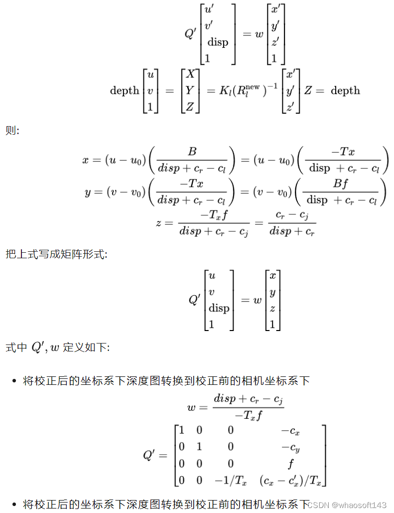
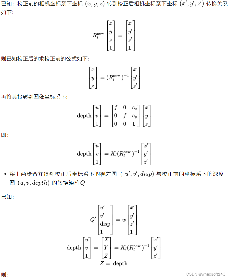
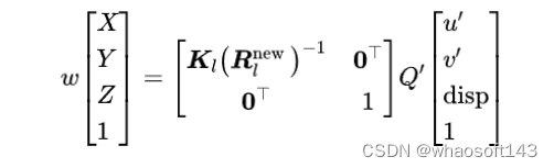
极线校正后的视差图转校正前的深度图怎么转,代码怎么实现?
视差图是校正后的坐标系下得到的值,首先将其转换为校正后坐标系下的深度图
- 代码实现
bool Image::StereoRectifyImages(const Image& image1, const Image& image2, const Point3fArr& points1, const Point3fArr& points2, Image8U3& rectifiedImage1, Image8U3& rectifiedImage2, Image8U& mask1, Image8U& mask2, Matrix3x3& H, Matrix4x4& Q)
{
 ASSERT(image1.IsValid() && image2.IsValid());
 ASSERT(image1.GetSize() == image1.image.size() && image2.GetSize() ==        image2.image.size());
 ASSERT(points1.size() && points2.size());

 #if 0
 { // display projection pairs
  std::vector<Point2f> matches1, matches2;
  FOREACH(i, points1) {
   matches1.emplace_back(reinterpret_cast<const Point2f&>(points1[i]));
   matches2.emplace_back(reinterpret_cast<const Point2f&>(points2[i]));
  }
  RECTIFY::DrawMatches(const_cast<Image8U3&>(image1.image),       const_cast<Image8U3&>(image2.image), matches1, matches2);
 }
 #endif

 // compute rectification
 // 校正计算
 Matrix3x3 K1, K2, R1, R2;
 #if 0
 const REAL t(Camera::StereoRectify(image1.GetSize(), image1.camera, image2.GetSize(), image2.camera, R1, R2, K1, K2));
 #elif 1
 const REAL t(Camera::StereoRectifyFusiello(image1.GetSize(), image1.camera, image2.GetSize(), image2.camera, R1, R2, K1, K2));
 #else
 Pose pose;
 ComputeRelativePose(image1.camera.R, image1.camera.C, image2.camera.R, image2.camera.C, pose.R, pose.C);
 cv::Mat P1, P2;
 cv::stereoRectify(image1.camera.K, cv::noArray(), image2.camera.K, cv::noArray(), image1.GetSize(), pose.R, Vec3(pose.GetTranslation()), R1, R2, P1, P2, Q, 0/*cv::CALIB_ZERO_DISPARITY*/, -1);
 K1 = P1(cv::Rect(0,0,3,3));
 K2 = P2(cv::Rect(0,0,3,3));
 const Point3 _t(R2 * pose.GetTranslation());
 ASSERT((ISZERO(_t.x) || ISZERO(_t.y)) && ISZERO(_t.z));
 const REAL t(ISZERO(_t.x)?_t.y:_t.x);
 #if 0
 cv::Mat map1, map2;
 cv::initUndistortRectifyMap(image1.camera.K, cv::noArray(), R1, K1, image1.GetSize(), CV_16SC2, map1, map2);
 cv::remap(image1.image, rectifiedImage1, map1, map2, cv::INTER_CUBIC);
 cv::initUndistortRectifyMap(image2.camera.K, cv::noArray(), R2, K2, image1.GetSize(), CV_16SC2, map1, map2);
 cv::remap(image2.image, rectifiedImage2, map1, map2, cv::INTER_CUBIC);
 return;
 #endif
 #endif
 if (ISZERO(t))
  return false;

 // adjust rectified camera matrices such that the entire area common to both source images is contained in the rectified images
 // 调整校正后的相机矩阵,使两个源图像的公共区域都包含在校正后的图像中
 cv::Size size1(image1.GetSize()), size2(image2.GetSize());
 if (!points1.empty())
  Camera::SetStereoRectificationROI(points1, size1, image1.camera, points2, size2, image2.camera, R1, R2, K1, K2);
 ASSERT(size1 == size2);

 // compute rectification homography (from original to rectified image)
 // 计算校正的单应性矩阵(描述的是两个图像像素坐标的转换矩阵H[u,v,1]^t=[u',v',1]^t)(从原始图像到校正图像)
 const Matrix3x3 H1(K1 * R1 * image1.camera.GetInvK()); H = H1;
 const Matrix3x3 H2(K2 * R2 * image2.camera.GetInvK());

 #if 0
 { // display epipolar lines before and after rectification
  Pose pose;
  ComputeRelativePose(image1.camera.R, image1.camera.C, image2.camera.R, image2.camera.C, pose.R, pose.C);
  const Matrix3x3 F(CreateF(pose.R, pose.C, image1.camera.K, image2.camera.K));
  std::vector<Point2f> matches1, matches2;
  #if 1
  FOREACH(i, points1) {
   matches1.emplace_back(reinterpret_cast<const Point2f&>(points1[i]));
   matches2.emplace_back(reinterpret_cast<const Point2f&>(points2[i]));
  }
  #endif
  RECTIFY::DrawRectifiedImages(image1.image.clone(), image2.image.clone(), F, H1, H2, matches1, matches2);
 }
 #endif

 // rectify images (apply homographies)
 // 校正图像,就是利用单应性矩阵,把原图像每个像素坐标转换到校正的图像下。
 rectifiedImage1.create(size1);
 cv::warpPerspective(image1.image, rectifiedImage1, H1, rectifiedImage1.size());
 rectifiedImage2.create(size2);
 cv::warpPerspective(image2.image, rectifiedImage2, H2, rectifiedImage2.size());

 // mark valid regions covered by the rectified images
 // 标记正确图像覆盖的有效区域
 struct Compute {
  static void Mask(Image8U& mask, const cv::Size& sizeh, const cv::Size& size, const Matrix3x3& H) {
   mask.create(sizeh);
   mask.memset(0);
   std::vector<Point2f> corners(4);
   corners[0] = Point2f(0,0);
   corners[1] = Point2f((float)size.width,0);
   corners[2] = Point2f((float)size.width,(float)size.height);
   corners[3] = Point2f(0,(float)size.height);
   cv::perspectiveTransform(corners, corners, H);
   std::vector<std::vector<Point2i>> contours(1);
   for (int i=0; i<4; ++i)
    contours.front().emplace_back(ROUND2INT(corners[i]));
   cv::drawContours(mask, contours, 0, cv::Scalar(255), cv::FILLED);
  }
 };
 Compute::Mask(mask1, size1, image1.GetSize(), H1);
 Compute::Mask(mask2, size2, image2.GetSize(), H2);

 // from the formula that relates disparity to depth as z=B*f/d where B=-t and d=x_l-x_r
 // and the formula that converts the image projection from right to left x_r=K1*K2.inv()*x_l
 // compute the inverse projection matrix that transforms image coordinates in image 1 and its
 // corresponding disparity value to the 3D point in camera 1 coordinates as:
 // 根据depth=Bf/d的关系,计算投影矩阵Q将校正的视差图转到为校正的深度图。
 ASSERT(ISEQUAL(K1(1,1),K2(1,1)));
 Q = Matrix4x4::ZERO;
 //   Q * [x, y, disparity, 1] = [X, Y, Z, 1] * w
 ASSERT(ISEQUAL(K1(0,0),K2(0,0)) && ISZERO(K1(0,1)) && ISZERO(K2(0,1)));
 Q(0,0) = Q(1,1) = REAL(1);
 Q(0,3) = -K1(0,2);
 Q(1,3) = -K1(1,2);
 Q(2,3) =  K1(0,0);
 Q(3,2) = -REAL(1)/t;
 Q(3,3) =  (K1(0,2)-K2(0,2))/t;

 // compute Q that converts disparity from rectified to depth in original image
 // 计算将视差从校正到原始图像深度转换的Q值
 Matrix4x4 P(Matrix4x4::IDENTITY);
 cv::Mat(image1.camera.K*R1.t()).copyTo(cv::Mat(4,4,cv::DataType<Matrix4x4::Type>::type,P.val)(cv::Rect(0,0,3,3)));
 Q = P*Q;
 return true;
}- 1.
- 2.
- 3.
- 4.
- 5.
- 6.
- 7.
- 8.
- 9.
- 10.
- 11.
- 12.
- 13.
- 14.
- 15.
- 16.
- 17.
- 18.
- 19.
- 20.
- 21.
- 22.
- 23.
- 24.
- 25.
- 26.
- 27.
- 28.
- 29.
- 30.
- 31.
- 32.
- 33.
- 34.
- 35.
- 36.
- 37.
- 38.
- 39.
- 40.
- 41.
- 42.
- 43.
- 44.
- 45.
- 46.
- 47.
- 48.
- 49.
- 50.
- 51.
- 52.
- 53.
- 54.
- 55.
- 56.
- 57.
- 58.
- 59.
- 60.
- 61.
- 62.
- 63.
- 64.
- 65.
- 66.
- 67.
- 68.
- 69.
- 70.
- 71.
- 72.
- 73.
- 74.
- 75.
- 76.
- 77.
- 78.
- 79.
- 80.
- 81.
- 82.
- 83.
- 84.
- 85.
- 86.
- 87.
- 88.
- 89.
- 90.
- 91.
- 92.
- 93.
- 94.
- 95.
- 96.
- 97.
- 98.
- 99.
- 100.
- 101.
- 102.
- 103.
- 104.
- 105.
- 106.
- 107.
- 108.
- 109.
- 110.
- 111.
- 112.
- 113.
- 114.
- 115.
- 116.
- 117.
- 118.
- 119.
- 120.
- 121.
- 122.
- 123.
- 124.
- 125.
- 根据求解的转换矩阵进行视差图和深度图相互转换
/**
 * @brief 根据原图的深度图计算校正后的图像的视差图,视差图事先根据有效尺寸分配好。
 *
 * @param[in] depthMap        原图的深度图
 * @param[in] invH      转换矩阵:把校正图的像素坐标转换到原图
 * @param[in] invQ            转换矩阵把[x*z y*z z 1]*w in original image coordinates(z即为depth) 转到[x' y' disparity 1] in rectified coordinates
 * @param[in] subpixelSteps   亚像素精度,如果是4则对于精度是0.25,主要是视差值存储的都是整型。所以得到的视差会乘这个值转成整型。具体转回float真值时会除掉这个数
 * @param[in] disparityMap    视差图
 */
void SemiGlobalMatcher::Depth2DisparityMap(const DepthMap& depthMap, const Matrix3x3& invH, const Matrix4x4& invQ, Disparity subpixelSteps, DisparityMap& disparityMap)
{
 auto pixel = [&](int, int r, int c) {
  // rc加half窗口的原因是视差图是有效像素开始的起始是从(halfWindowSizeX,halfWindowSizeY)开始的而非(0,0)
  const ImageRef x(c+halfWindowSizeX,r+halfWindowSizeY); Point2f u;
  //把校正图像上的像素坐标转到原图坐标上
  ProjectVertex_3x3_2_2(invH.val, x.ptr(), u.ptr());
  float depth, disparity;
  //取深度值depth并转到视差上
  if (!depthMap.sampleSafe(depth, u, [](Depth d) { return d > 0; }) || !Image::Depth2Disparity(invQ, u, depth, disparity))
   disparityMap(r,c) = NO_DISP;
  else
   disparityMap(r,c) = (Disparity)ROUND2INT(disparity*subpixelSteps);
 };
 ASSERT(threads.IsEmpty());
 if (!threads.empty()) {
  volatile Thread::safe_t idxPixel(-1);
  FOREACH(i, threads)
   threads.AddEvent(new EVTPixelProcess(disparityMap.size(), idxPixel, pixel));
  WaitThreadWorkers(threads.size());
 } else
 for (int r=0; r<disparityMap.rows; ++r)
  for (int c=0; c<disparityMap.cols; ++c)
   pixel(-1, r, c);
}

// Compute the depth-map for the un-rectified image from the given disparity-map of the rectified image
// 同上反向即可
void SemiGlobalMatcher::Disparity2DepthMap(const DisparityMap& disparityMap, const AccumCostMap& costMap, const Matrix3x3& H, const Matrix4x4& Q, Disparity subpixelSteps, DepthMap& depthMap, ConfidenceMap& confMap)
{
 ASSERT(costMap.empty() || costMap.size() == disparityMap.size());
 ASSERT(!depthMap.empty());
 ASSERT(confMap.empty() || confMap.size() == depthMap.size());

 if (!costMap.empty()) {
  confMap.create(depthMap.size());
  auto pixel = [&](int, int r, int c) {
   const ImageRef x(c,r); Point2f u;
   ProjectVertex_3x3_2_2(H.val, x.ptr(), u.ptr());
   u.x -= halfWindowSizeX; u.y -= halfWindowSizeY;
   float disparity;
   if (!disparityMap.sampleSafe(disparity, u, [](Disparity d) { return d != NO_DISP; })) {
    depthMap(x) = 0;
    confMap(x) = 0;
    return;
   }
   float cost;
   costMap.sampleSafe(cost, u, [](AccumCost c) { return c != NO_ACCUMCOST; });
   depthMap(x) = Image::Disparity2Depth(Q, u, disparity/subpixelSteps);
   confMap(x) = 1.f/(cost+1);
  };
  ASSERT(threads.IsEmpty());
  if (!threads.empty()) {
   volatile Thread::safe_t idxPixel(-1);
   FOREACH(i, threads)
    threads.AddEvent(new EVTPixelProcess(depthMap.size(), idxPixel, pixel));
   WaitThreadWorkers(threads.size());
  } else
  for (int r=0; r<depthMap.rows; ++r)
   for (int c=0; c<depthMap.cols; ++c)
    pixel(-1, r, c);
 } else {
  auto pixel = [&](int, int r, int c) {
   const ImageRef x(c,r); Point2f u;
   ProjectVertex_3x3_2_2(H.val, x.ptr(), u.ptr());
   u.x -= halfWindowSizeX; u.y -= halfWindowSizeY;
   float disparity;
   if (!disparityMap.sampleSafe(disparity, u, [](Disparity d) { return d != NO_DISP; }))
    depthMap(x) = 0;
   else
    depthMap(x) = Image::Disparity2Depth(Q, u, disparity/subpixelSteps);
  };
  ASSERT(threads.IsEmpty());
  if (!threads.empty()) {
   volatile Thread::safe_t idxPixel(-1);
   FOREACH(i, threads)
    threads.AddEvent(new EVTPixelProcess(depthMap.size(), idxPixel, pixel));
   WaitThreadWorkers(threads.size());
  } else
  for (int r=0; r<depthMap.rows; ++r)
   for (int c=0; c<depthMap.cols; ++c)
    pixel(-1, r, c);
 }
}- 1.
- 2.
- 3.
- 4.
- 5.
- 6.
- 7.
- 8.
- 9.
- 10.
- 11.
- 12.
- 13.
- 14.
- 15.
- 16.
- 17.
- 18.
- 19.
- 20.
- 21.
- 22.
- 23.
- 24.
- 25.
- 26.
- 27.
- 28.
- 29.
- 30.
- 31.
- 32.
- 33.
- 34.
- 35.
- 36.
- 37.
- 38.
- 39.
- 40.
- 41.
- 42.
- 43.
- 44.
- 45.
- 46.
- 47.
- 48.
- 49.
- 50.
- 51.
- 52.
- 53.
- 54.
- 55.
- 56.
- 57.
- 58.
- 59.
- 60.
- 61.
- 62.
- 63.
- 64.
- 65.
- 66.
- 67.
- 68.
- 69.
- 70.
- 71.
- 72.
- 73.
- 74.
- 75.
- 76.
- 77.
- 78.
- 79.
- 80.
- 81.
- 82.
- 83.
- 84.
- 85.
- 86.
- 87.
- 88.
- 89.
- 90.
- 91.
- 92.
- 93.


 2217
2217

 被折叠的 条评论
为什么被折叠?
被折叠的 条评论
为什么被折叠?
 到【灌水乐园】发言


