


Arduino ESP32 双核任务运行
ESP32中S和S3系列是双核,也就是一个CPU在工作的时候同时运行另一个CPU。ESP32的Arduino core在使用多任务的前提下,Arduino ESP32 核心程序底层使用的是FreeRTOS 的实时操作系统创建的。
- 所以对于ESP32本身,就是基于
FreeRTOS在跑,只是没有看到底部的封装层代码。
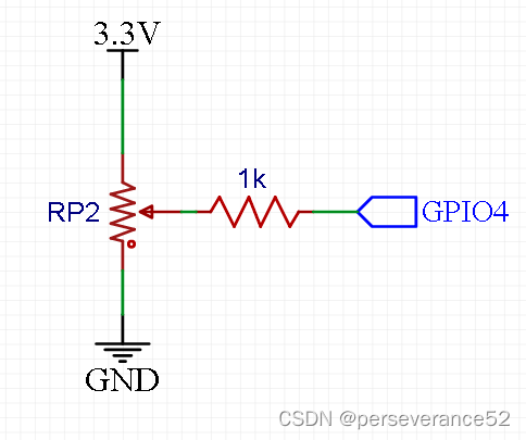
- 🧲定位器接线示意图:
📑ESP32 FreeRTOS API函数介绍
xTaskCreatePinnedToCore(……):
BaseType_t xTaskCreatePinnedToCore( TaskFunction_t pvTaskCode,           	 //任务名 这里直接是函数名
                                        const char * const pcName,           //任务名字 字符串 最大长度在FreeRTOSConfig.h中有限制,ESP32中最大16个字符
                                        const uint32_t usStackDepth,         //任务堆栈大小,总体的大小是要乘以 4 单位 byte usStackDepth 单位是字word
                                        void * const pvParameters,           //给任务传入参数,这个参数可以是任意类型的
                                        UBaseType_t uxPriority,              //任务优先级别 空闲优先级是0 0最低,往上就越高 最大值在FreeRTOSConfig.h 中设置
                                        TaskHandle_t * const pvCreatedTask,  //任务句柄 方便对任务的一些操作,例如删除、挂起传入任务句柄作为参数的
                                        const BaseType_t xCoreID);           //任务创建在哪个核
pvTaskCode: 指向任务输入函数的指针。 任务必须实现永不返回(即连续循环),或者应该使用vTaskDelete函数终止。pcName任务的描述性名称。 这主要是为了方便调试。 最大长度由configMAX_TASK_NAME_LEN定义 - 默认是16。usStackDepth: 任务栈的大小,以字节数表示。字节数。注意,这与vanilla FreeRTOS不同。pvParameters: 指针将被用作任务的参数。- u
xPriority: 任务运行的优先级。 系统包括MPU支持的系统可以选择在特权(系统)下创建任务。通过设置优先级参数的位portPRIVILEGE_BIT来创建任务。
要创建一个优先级为2的特权任务,- -uxPriority参数应该被设置为 ( 2 | portPRIVILEGE_BIT )。
pvCreatedTask: 用于传回一个句柄,创建的任务可以通过它来引用。可以被引用。xCoreID: 如果该值为tskNO_AFFINITY,则创建的任务不被锁定在CPU核心上。调度器可以在任何可用的核心上运行它。值为0或1时,表示该任务应该被指定到CPU上的核心上运行。指定参数大于(portNUM_PROCESSORS - 1)的值将导致函数失败。导致该函数失败。
如果任务被成功创建并添加到准备好的列表中,返回pdPASS列表中,否则会有一个错误代码,该代码在文件projdefs.h中定义。
✨ESP32多核心跑RTOS任务注意事项
- 在使用WIFI或蓝牙的情况下,请不要调用核心0,不然会影响通讯。
- 在执行比较费时的任务函数前,最好执行一次喂狗。
- 在多核心执行任务函数中需要有死循环。
- 执行多核心任务都可能需要附加一定的延时时间。
📝实例代码一
/*
多任务运行(读取模拟量与闪灯)
接脚说明:2脚为板载LED,4脚接电位器OUT
*/
#if CONFIG_FREERTOS_UNICORE
#define ARDUINO_RUNNING_CORE 0
#else
#define ARDUINO_RUNNING_CORE 1
#endif
#ifndef LED_BUILTIN
#define LED_BUILTIN 2
#endif
// 为 Blink 和 AnalogRead 定义两个任务
void TaskBlink( void *pvParameters );
void TaskAnalogReadA3( void *pvParameters );
// the setup function runs once when you press reset or power the board
void setup() {
// initialize serial communication at 115200 bits per second:
Serial.begin(115200);
// Now set up two tasks to run independently.
xTaskCreatePinnedToCore(
TaskBlink
, "TaskBlink" // 任务名
, 1024 // This stack size can be checked & adjusted by reading the Stack Highwater
, NULL
, 2 // 任务优先级, with 3 (configMAX_PRIORITIES - 1) 是最高的,0是最低的.
, NULL
, ARDUINO_RUNNING_CORE);
xTaskCreatePinnedToCore(
TaskAnalogReadA3
, "AnalogReadA3" //任务名
, 1024 // 栈大小
, NULL
, 1 // 任务优先级
, NULL
, ARDUINO_RUNNING_CORE);
//现在,接管单个任务调度控制的任务调度程序将自动启动。
}
void loop()
{
// Empty. Things are done in Tasks.
}
/*--------------------------------------------------*/
/*---------------------- Tasks ---------------------*/
/*--------------------------------------------------*/
void TaskBlink(void *pvParameters) // This is a task.
{
(void) pvParameters;
/*
Blink
Turns on an LED on for one second, then off for one second, repeatedly.
If you want to know what pin the on-board LED is connected to on your ESP32 model, check
the Technical Specs of your board.
*/
// initialize digital LED_BUILTIN on pin 13 as an output.
pinMode(LED_BUILTIN, OUTPUT);
for (;;) // A Task shall never return or exit.
{
digitalWrite(LED_BUILTIN, HIGH); // turn the LED on (HIGH is the voltage level)
vTaskDelay(1000); // one tick delay (15ms) in between reads for stability
digitalWrite(LED_BUILTIN, LOW); // turn the LED off by making the voltage LOW
vTaskDelay(1000); // one tick delay (15ms) in between reads for stability
}
}
void TaskAnalogReadA3(void *pvParameters) // This is a task.
{
(void) pvParameters;
/*
AnalogReadSerial
Reads an analog input on pin A4, prints the result to the serial monitor.
Graphical representation is available using serial plotter (Tools > Serial Plotter menu)
Attach the center pin of a potentiometer to pin A3, and the outside pins to +5V and ground.
This example code is in the public domain.
*/
for (;;)
{
// read the input on analog pin 4:
int sensorValueA4 = analogRead(4);
// print out the value you read:
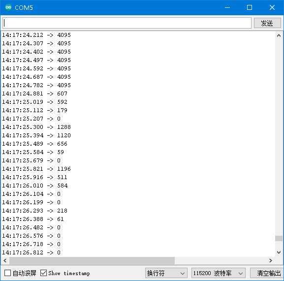
Serial.println(sensorValueA4);
vTaskDelay(100); // one tick delay (15ms) in between reads for stability
}
}
- 串口打印信息
📘测试代码二
🎉这是一个使用esp32使用LEDC,跑双核任务,生成SVPWM驱动无刷电机实际测试代码。其中涉及了双核任务,喂狗程序的使用。
TaskHandle_t th_p[2];

long a_Task = 0;
long b_Task = 0;
long c_Task = 0;
void Core0task(void *args) {
    while(1){ // 多线程中必须使用一个死循环
        b_Task++;
        delayMicroseconds(150); // 添加延迟1ms,可以有效防止卡死,避免运行报错。
    }
}

void Core1task(void *args) {
    while(1){ // 多线程中必须使用一个死循环
        c_Task++;
       delayMicroseconds(200);
    }
}

void setup() {
    Serial.begin(115200);
    xTaskCreatePinnedToCore(Core0task, "Core0task", 4096, NULL, 3, &th_p[0], 0);
    xTaskCreatePinnedToCore(Core1task, "Core1task", 4096, NULL, 4, &th_p[1], 1);
}

void loop() {
    a_Task++;
    Serial.print("a_Task = ")
    Serial.println(a_Task);
    Serial.print("b_Task = ")
    Serial.println(b_Task);
  Serial.print("c_Task = ")
    Serial.println(c_Task);
    delay(1000);
}
📙多核心实战使用例程
/*
 * 日期:2023.7.22
 * 开环速度控制代码
 *  进行串口调试,波特率需要设置为57600
 * 电机参数 A2212/15T的极对数:7
 *
 */
#include <Arduino.h>
#include <math.h>
#include "soc/rtc_wdt.h" //设置看门狗用
#include "freertos/FreeRTOS.h"
#include "freertos/task.h"
#include "freertos/queue.h"
#include "driver/ledc.h"
#include "esp_log.h"
#include "esp_system.h"
#include "esp_timer.h"
#include "esp_attr.h"
#include "esp_intr_alloc.h"
#include "esp_err.h"
#include "esp_task_wdt.h"

#define VOFA_SERIAL     // 使用vofa+串口调试器查看马鞍波波形
const int poles = 7;  // 电机的极对数

// PWM输出引脚定义
// 定义LEDC通道、GPIO引脚和分辨率
#define LEDC_CHANNEL1    0
#define LEDC_CHANNEL2    1
#define LEDC_CHANNEL3    2

#define LEDC_GPIO1 5
#define LEDC_GPIO2 18
#define LEDC_GPIO3 19

#define LEDC_RESOLUTION 10 // 设置分辨率为10位
#define PWM_FREQ 15000 // 设置PWM频率为10000Hz

// const char pwmA = 5;
// const char pwmB = 18;
// const char pwmC = 19;

const float voltagePowerSupply = 12.0;
float open_loop_timestamp = 0;
float shaft_angle = 0; // 机械角度
float zero_electric_angle = 0;
float Ualpha, Ubeta = 0;
float Ua = 0, Ub = 0, Uc = 0;
float dc_a = 0, dc_b = 0, dc_c = 0;

//#define PI 3.14159265359
#define PI_2 1.57079632679
#define PI_3 1.0471975512
#define _SQRT3 1.73205080757

TaskHandle_t th_p[2];

/**  电角度 = 机械角度 * 极对数
 * @brief 电角度计算函数
 * @param shaft_angle 机械角度
 * @param pole_pairs 电机的极对数
*/
float _electricalAngle(float shaft_angle, int pole_pairs)
{
    return (shaft_angle * pole_pairs);
}


/**角度归一化到[0, 2pi],把输入的角度限制在[0, 2pi]
 * @brief 角度归一化函数
 * @param angle 输入的角度
 * @return 归一化后的角度
 * 例如:_normalizeAngle(3.1415926) 返回 0
*/
float _normalizeAngle(float angle)
{
    float a = fmod(angle, 2 * PI); // 取余,结果可能为负值
    return a >= 0 ? a : (a + 2 * PI);
}


/**设置PWM输出
 * @brief 设置PWM输出
 * @param Ua 电机A的占空比
 * @param Ub 电机B的占空比
 * @param Uc 电机C的占空比
*/
void setPwm(float Ua, float Ub, float Uc)
{

    // 计算占空比,并使用constrain()函数限制相电压的范围0到1
    dc_a = constrain(Ua / voltagePowerSupply, 0.0f, 1.0f);
    dc_b = constrain(Ub / voltagePowerSupply, 0.0f, 1.0f);
    dc_c = constrain(Uc / voltagePowerSupply, 0.0f, 1.0f);

    // 写入PWM到PWM 0 1 2 通道
    ledcWrite(0, static_cast<uint32_t>(dc_a * 1023));  //使用10位分辨率计算占空比值
    ledcWrite(1, static_cast<uint32_t>(dc_b * 1023));
    ledcWrite(2, static_cast<uint32_t>(dc_c * 1023));


}

/**
 * @brief 设置相位电压
 * @param Uq 电流值
 * @param Ud 电压值
 * @param angle_el 电机的电角度,单位 rad
 * 电角度 = 机械角度 * 极对数
 * 机械角度 = 电角度 / 极对数
*/
void setPhaseVoltage(float Uq, float Ud, float angle_el)
{
    angle_el = _normalizeAngle(angle_el + zero_electric_angle); // 电角度

    // 帕克逆变换
    Ualpha = -Uq * sin(angle_el);
    Ubeta = Uq * cos(angle_el);

    // 克拉克逆变换
    Ua = Ualpha + voltagePowerSupply / 2;
    Ub = (sqrt(3) * Ubeta - Ualpha) / 2 + voltagePowerSupply / 2;
    Uc = (-Ualpha - sqrt(3) * Ubeta) / 2 + voltagePowerSupply / 2;
    setPwm(Ua, Ub, Uc);

}

void setTorque(float Uq, float angle_el) {
 if (Uq < 0)
    angle_el += PI;
  Uq = abs(Uq);

  angle_el = _normalizeAngle(angle_el + PI_2);
  int sector = floor(angle_el / PI_3) + 1;
  // calculate the duty cycles
  float T1 = _SQRT3 * sin(sector * PI_3 - angle_el) * Uq / voltagePowerSupply;
  float T2 = _SQRT3 * sin(angle_el - (sector - 1.0) * PI_3) * Uq / voltagePowerSupply;
  float T0 = 1 - T1 - T2;

  float Ta, Tb, Tc;
  switch (sector)
  {
  case 1:
    Ta = T1 + T2 + T0 / 2;
    Tb = T2 + T0 / 2;
    Tc = T0 / 2;
    break;
  case 2:
    Ta = T1 + T0 / 2;
    Tb = T1 + T2 + T0 / 2;
    Tc = T0 / 2;
    break;
  case 3:
    Ta = T0 / 2;
    Tb = T1 + T2 + T0 / 2;
    Tc = T2 + T0 / 2;
    break;
  case 4:
    Ta = T0 / 2;
    Tb = T1 + T0 / 2;
    Tc = T1 + T2 + T0 / 2;
    break;
  case 5:
    Ta = T2 + T0 / 2;
    Tb = T0 / 2;
    Tc = T1 + T2 + T0 / 2;
    break;
  case 6:
    Ta = T1 + T2 + T0 / 2;
    Tb = T0 / 2;
    Tc = T1 + T0 / 2;
    break;
  default:
    Ta = 0;
    Tb = 0;
    Tc = 0;
  }

  float Ua = Ta * voltagePowerSupply;
  float Ub = Tb * voltagePowerSupply;
  float Uc = Tc * voltagePowerSupply;

  setPwm(Ua, Ub, Uc);

}

/** 开环速度函数,Uq和电角度生成器
 * @brief 开环速度控制函数
 * @param target_velocity 目标速度,单位 rad/s
 * @return 返回Uq值,用于控制电机转速
 */
float velocityOpenloop(float target_velocity)
{
  //  unsigned long now_us = micros(); // 获取从开启芯片以来的微秒数,它的精度是 4 微秒。 micros() 返回的是一个无符号长整型(unsigned long)的值
    //影响T周期
     float deltaT = 4.2e-4f;     // 给定一个固定的开环运行时间间隔6.5e-5f 8.4e-5f 8.4e-3f 1.7e-2f
    // 计算当前每个Loop的运行时间间隔
//unsigned long mid_value = now_us - open_loop_timestamp;
//Serial.println(mid_value);
    // 计算当前每个Loop的运行时间间隔
  //  float deltaT = mid_value * 1e-6f;
    // 计算电机轴的机械角度


    // 计算电机轴的电角度
  //  float Ts = (now_us - open_loop_timestamp) * 1e-6f;
 //float Ts = mid_value * 1e-6f;
    // 由于 micros() 函数返回的时间戳会在大约 70 分钟之后重新开始计数,在由70分钟跳变到0时,TS会出现异常,因此需要进行修正。如果时间间隔小于等于零或大于 0.5 秒,则将其设置为一个较小的默认值,即 1e-3f
//    if (Ts <= 0 || Ts > 0.5f)
//        Ts = 6.5e-5f;

    // 通过乘以时间间隔和目标速度来计算需要转动的机械角度,存储在 shaft_angle 变量中。在此之前,还需要对轴角度进行归一化,以确保其值在 0 到 2π 之间。
 //   shaft_angle = _normalizeAngle(shaft_angle + target_velocity * Ts);
   shaft_angle = _normalizeAngle(shaft_angle + target_velocity * deltaT);
    // 以目标速度为 10 rad/s 为例,如果时间间隔是 1 秒,则在每个循环中需要增加 10 * 1 = 10 弧度的角度变化量,才能使电机转动到目标速度。
    // 如果时间间隔是 0.1 秒,那么在每个循环中需要增加的角度变化量就是 10 * 0.1 = 1 弧度,才能实现相同的目标速度。因此,电机轴的转动角度取决于目标速度和时间间隔的乘积。

    // 设置的voltage_power_supply的1/3作为Uq值,这个值会直接影响输出力矩
    // 最大只能设置为Uq = voltage_power_supply/2,否则ua,ub,uc会超出供电电压限幅
    float Uq = voltagePowerSupply / 24;

   // setPhaseVoltage(Uq, 0, _electricalAngle(shaft_angle, poles)); // 极对数可以设置为常量
    setTorque(0.35f,  _electricalAngle(shaft_angle, poles));//Uq影响振幅,力矩大小
 //   open_loop_timestamp = now_us; // 用于计算下一个时间间隔

    return Uq;
}

void Core0task(void *args) {
    while(1){ // 多线程中必须使用一个死循环
      #ifdef VOFA_SERIAL
    rtc_wdt_feed();  //喂狗函数
    Serial.printf("%f,%f,%f\n", dc_a, dc_b, dc_c);
    vTaskDelay(1);//1000 / portTICK_PERIOD_MS
    yield();

    #endif
}

}

void Core1task(void *args) {
    while(1){ // 多线程中必须使用一个死循环
    rtc_wdt_feed();  //喂狗函数
       velocityOpenloop(6.0f);//数值越大,电机旋转的速度越快 。(Limited:0 到 2π 之间)
       vTaskDelay(1);//1000 / portTICK_PERIOD_MS
       yield();

    }
}

void setup()
{
    Serial.begin(576000);
    rtc_wdt_protect_off();     //看门狗写保护关闭 关闭后可以喂狗
    //rtc_wdt_protect_on();    //看门狗写保护打开 打开后不能喂狗
  //rtc_wdt_disable();       //禁用看门狗
  rtc_wdt_enable();          //启用看门狗
    rtc_wdt_set_time(RTC_WDT_STAGE0,1000); //看门狗超时时间设置为1秒
    // PWM设置
    pinMode(LEDC_GPIO1, OUTPUT);
    pinMode(LEDC_GPIO2, OUTPUT);
    pinMode(LEDC_GPIO3, OUTPUT);

    ledcSetup(LEDC_CHANNEL1, PWM_FREQ, LEDC_RESOLUTION); // pwm通道(1-16), 频率, 精度(0-14)
    ledcAttachPin(LEDC_GPIO1, 0); // 将GPIO引脚与LEDC通道关联,这样才能让LEDC信号输出到这个引脚
    ledcSetup(LEDC_CHANNEL2, PWM_FREQ, LEDC_RESOLUTION); // pwm通道, 频率, 精度
    ledcAttachPin(LEDC_GPIO2, 1); // 将GPIO引脚与LEDC通道关联
    ledcSetup(LEDC_CHANNEL3, PWM_FREQ, LEDC_RESOLUTION); // pwm通道, 频率, 精度
    ledcAttachPin(LEDC_GPIO3, 2); // 将GPIO引脚与LEDC通道关联

    // 创建两个任务
    xTaskCreatePinnedToCore(Core0task, "Core0task", 1024, NULL, 3, &th_p[0], 0);
    xTaskCreatePinnedToCore(Core1task, "Core1task", 4096, NULL, 4, &th_p[1], 1);
    Serial.println("完成PWM初始化设置");
    delay(3000);
}

void loop()
{
   // velocityOpenloop(6.0f);//数值越大,电机旋转的速度越快 。(Limited:0 到 2π 之间)


}


 1558
1558


 被折叠的 条评论
为什么被折叠?
被折叠的 条评论
为什么被折叠?
 到【灌水乐园】发言


