


STM32G070RBT6基于Arduino框架ADC输入电压检测
- 📌相关篇《【硬件开源电路】STM32G070RBT6开发板》

📚模数转换器(ADC)
📑在STM32G070CB/KB/RB设备中嵌入了一个本地的12位模数转换器。它可以通过硬件采样扩展到16位分辨率。ADC最多有16个外部通道和3个内部通道(温度传感器、电压参考、VBAT监测)。
📗ADC引脚
PA0 -PA7
ADC0 - ADC7
-----------
PB0- PB12
ADC8 - ADC16
----------
PC4 -PC5
ADC17 - ADC18
- 🛠Arduino IDE有关ADC引脚定义位置:
C:\Users\Administrator\AppData\Local\Arduino15\packages\STMicroelectronics\hardware\stm32\2.3.0\cores\arduino\pins_arduino_analog.h
/* If NUM_ANALOG_INPUTS is not defined there is no analog pins defined. */
/* Anyway ADC internal channels are always available. */
#if NUM_ANALOG_INPUTS > 0
#define PIN_A0       PNUM_ANALOG_BASE
#if NUM_ANALOG_INPUTS > 1
  #define PIN_A1      (PIN_A0 + 1)
#endif
#if NUM_ANALOG_INPUTS > 2
  #define PIN_A2      (PIN_A1 + 1)
#endif
#if NUM_ANALOG_INPUTS > 3
  #define PIN_A3      (PIN_A2 + 1)
#endif
#if NUM_ANALOG_INPUTS > 4
  #define PIN_A4      (PIN_A3 + 1)
#endif
#if NUM_ANALOG_INPUTS > 5
  #define PIN_A5      (PIN_A4 + 1)
#endif
#if NUM_ANALOG_INPUTS > 6
  #define PIN_A6      (PIN_A5 + 1)
#endif
#if NUM_ANALOG_INPUTS > 7
  #define PIN_A7      (PIN_A6 + 1)
#endif
#if NUM_ANALOG_INPUTS > 8
  #define PIN_A8      (PIN_A7 + 1)
#endif
#if NUM_ANALOG_INPUTS > 9
  #define PIN_A9      (PIN_A8 + 1)
#endif
#if NUM_ANALOG_INPUTS > 10
  #define PIN_A10      (PIN_A9 + 1)
#endif
#if NUM_ANALOG_INPUTS > 11
  #define PIN_A11      (PIN_A10 + 1)
#endif
#if NUM_ANALOG_INPUTS > 12
  #define PIN_A12      (PIN_A11 + 1)
#endif
#if NUM_ANALOG_INPUTS > 13
  #define PIN_A13      (PIN_A12 + 1)
#endif
#if NUM_ANALOG_INPUTS > 14
  #define PIN_A14      (PIN_A13 + 1)
#endif
#if NUM_ANALOG_INPUTS > 15
  #define PIN_A15      (PIN_A14 + 1)
#endif
#if NUM_ANALOG_INPUTS > 16
  #define PIN_A16      (PIN_A15 + 1)
#endif
#if NUM_ANALOG_INPUTS > 17
  #define PIN_A17      (PIN_A16 + 1)
#endif
#if NUM_ANALOG_INPUTS > 18
  #define PIN_A18      (PIN_A17 + 1)
#endif
#if NUM_ANALOG_INPUTS > 19
  #define PIN_A19      (PIN_A18 + 1)
#endif
#if NUM_ANALOG_INPUTS > 20
  #define PIN_A20      (PIN_A19 + 1)
#endif
... ...
C:\Users\Administrator\.platformio\packages\framework-arduinoststm32\cores\arduino\stm32\PinNames.h
typedef enum {
  // Not connected
  NC = 0xFFFFFFFF,

  // Pin name definition
  PA_0  = (PortA << 4) + 0x00,
  PA_1  = (PortA << 4) + 0x01,
  PA_2  = (PortA << 4) + 0x02,
  PA_3  = (PortA << 4) + 0x03,
  PA_4  = (PortA << 4) + 0x04,
  PA_5  = (PortA << 4) + 0x05,
  PA_6  = (PortA << 4) + 0x06,
  PA_7  = (PortA << 4) + 0x07,
  PA_8  = (PortA << 4) + 0x08,
  PA_9  = (PortA << 4) + 0x09,
  PA_10 = (PortA << 4) + 0x0A,
  PA_11 = (PortA << 4) + 0x0B,
  PA_12 = (PortA << 4) + 0x0C,
  PA_13 = (PortA << 4) + 0x0D,
  PA_14 = (PortA << 4) + 0x0E,
  PA_15 = (PortA << 4) + 0x0F,

  PB_0  = (PortB << 4) + 0x00,
  PB_1  = (PortB << 4) + 0x01,
  PB_2  = (PortB << 4) + 0x02,
  PB_3  = (PortB << 4) + 0x03,
  PB_4  = (PortB << 4) + 0x04,
  PB_5  = (PortB << 4) + 0x05,
  PB_6  = (PortB << 4) + 0x06,
  PB_7  = (PortB << 4) + 0x07,
  PB_8  = (PortB << 4) + 0x08,
  PB_9  = (PortB << 4) + 0x09,
  PB_10 = (PortB << 4) + 0x0A,
  PB_11 = (PortB << 4) + 0x0B,
  PB_12 = (PortB << 4) + 0x0C,
  PB_13 = (PortB << 4) + 0x0D,
  PB_14 = (PortB << 4) + 0x0E,
  PB_15 = (PortB << 4) + 0x0F,
#if defined GPIOC_BASE
  PC_0  = (PortC << 4) + 0x00,
  PC_1  = (PortC << 4) + 0x01,
  PC_2  = (PortC << 4) + 0x02,
  PC_3  = (PortC << 4) + 0x03,
  PC_4  = (PortC << 4) + 0x04,
  PC_5  = (PortC << 4) + 0x05,
  PC_6  = (PortC << 4) + 0x06,
  PC_7  = (PortC << 4) + 0x07,
  PC_8  = (PortC << 4) + 0x08,
  PC_9  = (PortC << 4) + 0x09,
  PC_10 = (PortC << 4) + 0x0A,
  PC_11 = (PortC << 4) + 0x0B,
  PC_12 = (PortC << 4) + 0x0C,
  PC_13 = (PortC << 4) + 0x0D,
  PC_14 = (PortC << 4) + 0x0E,
  PC_15 = (PortC << 4) + 0x0F,
#endif
... ...
🔨模拟输入相关函数
文件位置:
C:\Users\Administrator\AppData\Local\Arduino15\packages\STMicroelectronics\hardware\stm32\2.3.0\cores\arduino\wiring_analog.h
/*
 * \brief Configures the reference voltage used for analog input (i.e. the value used as the top of the input range).
 * 配置用于模拟输入的参考电压(即作为输入范围的参考值)。
 * This function is kept only for compatibility with existing AVR based API.
 *
 * \param ulMmode Should be set to AR_DEFAULT.
 */
extern void analogReference(eAnalogReference ulMode) ;

/*
 * \brief Writes an analog value (PWM wave) to a pin.
 *将模拟值(PWM波)写入引脚。
 * \param ulPin
 * \param ulValue
 */
extern void analogWrite(uint32_t ulPin, uint32_t ulValue) ;

/*
 * \brief Reads the value from the specified analog pin.
 *从指定的模拟引脚读取值。
 * \param ulPin
 *
 * \return Read value from selected pin, if no error.
 */
extern uint32_t analogRead(uint32_t ulPin) ;

/*
 * \brief Set the resolution of analogRead return values. Default is 10 bits (range from 0 to 1023).
 *设置analogRead返回值的解析。默认为10位(范围从0到1023)。
 * \param res
 */
extern void analogReadResolution(int res);

/*
 * \brief Set the resolution of analogWrite parameters. Default is 8 bits (range from 0 to 255).
 * brief设置analogWrite参数的分辨率。默认为8位(范围从0到255)。
 * \param res
 */
extern void analogWriteResolution(int res);

/*
 * \brief Set the frequency of analogWrite. Default is PWM_FREQUENCY (1000) in Hertz.
 * 设置模拟写入的频率。默认值为PWM_FREQUENCY(1000),单位为赫兹。
 * \param freq
 */
extern void analogWriteFrequency(uint32_t freq);


extern void analogOutputInit(void) ;
- 🗝模拟引脚设置相关函数
文件位置:
C:\Users\Administrator\AppData\Local\Arduino15\packages\STMicroelectronics\hardware\stm32\2.3.0\cores\arduino\pins_arduino.h
bool digitalpinIsAnalogInput(uint32_t pin);//读取引脚是否为模拟输入引脚
uint32_t digitalPinToAnalogInput(uint32_t pin);//设置模拟引脚
🌼示例代码
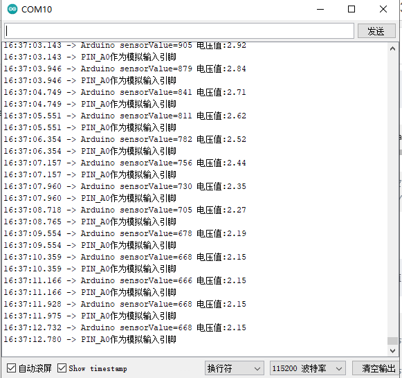
🔖将PA0作为模拟输入引脚,读取PA0的模拟值,转换为电压值,默认采用精度是10位,通过串口打印出来。
#define ADC_Pin  (PA0)
// the setup routine runs once when you press reset:
void setup() {

      Serial.setRx(PA10);
    Serial.setTx(PA9); //指定串口1引脚,默认是PA2、PA1
  Serial.begin(115200);
//   pinMode(ADC_Pin, INPUT);
analogInputToDigitalPin(PIN_A0);//同上
}

// the loop routine runs over and over again forever:
void loop() {
  // read the input on analog pin 0:
  int sensorValue = analogRead(ADC_Pin);
  Serial.printf("Arduino sensorValue=%d 电压值:",sensorValue);
//   Serial.print(sensorValue);
  // Convert the analog reading (which goes from 0 - 1023) to a voltage (0 -3.3V):
  float voltage = sensorValue * (3.3 / 1023.0);
  // print out the value you read:
  Serial.println(voltage);
  ADC_Pin_flag = digitalpinIsAnalogInput(0) == 1 ? Serial.println("PIN_A0作为模拟输入引脚") : Serial.println("PIN_A0不是模拟输入引脚");//读取0号引脚是否为模拟输入引脚

  delay(800);
}
- 📜串口打印
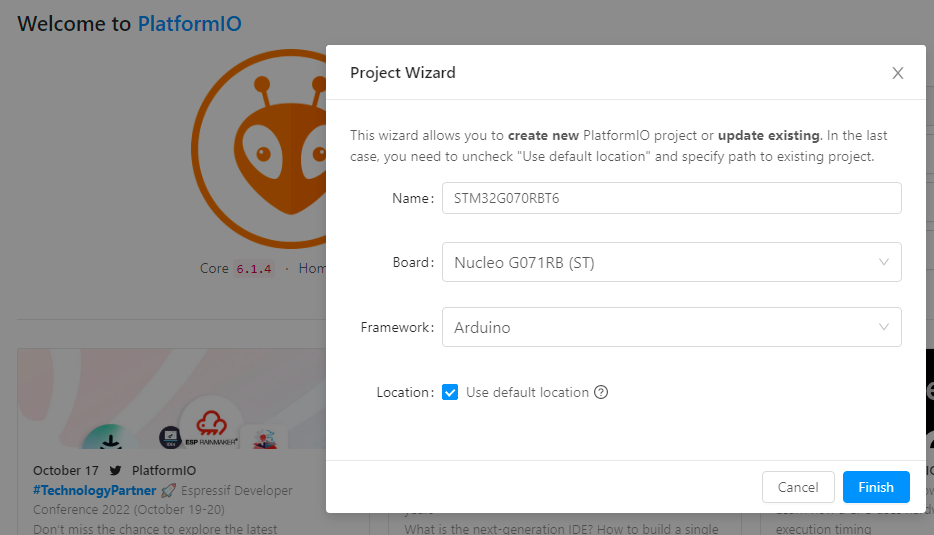
VSCode PIO开发配置
-
选择
Nucleo G071RB开发板,替代STM32G070RBT6此型号。
-
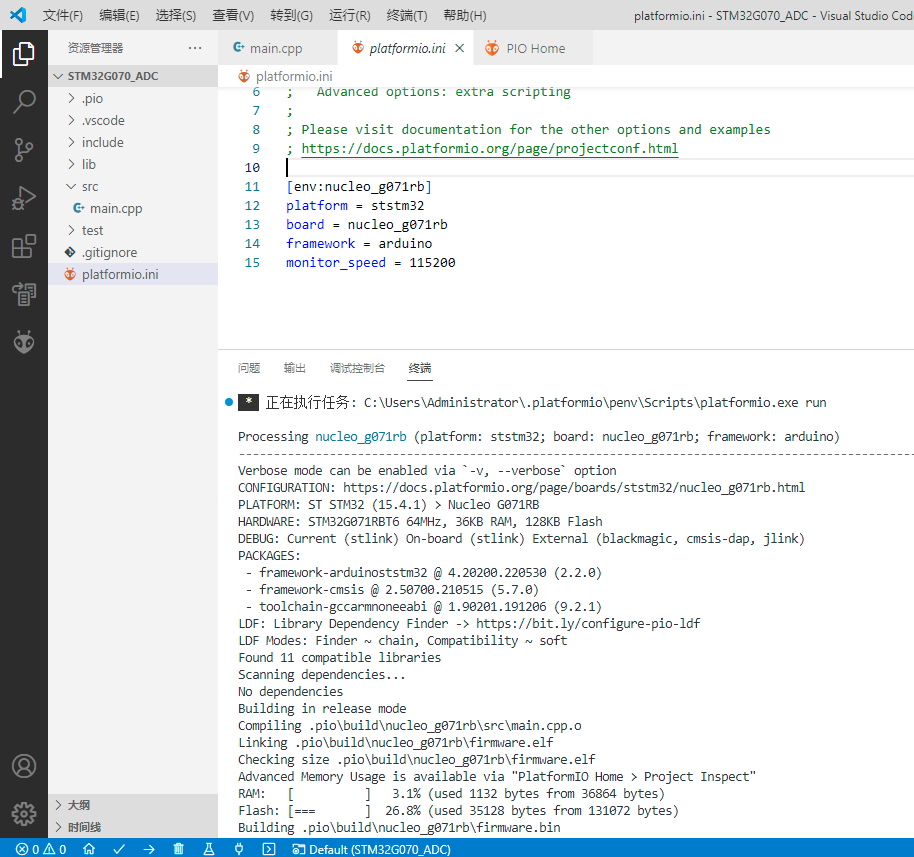
VSCode PIO配置项
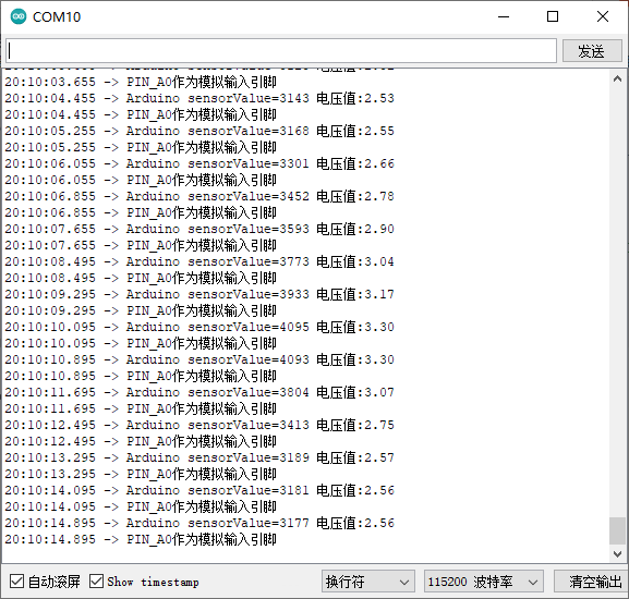
🌴12位精度采集示例
/*
  ReadAnalogVoltage

  Reads an analog input on pin 0, converts it to voltage, and prints the result to the Serial Monitor.
  Graphical representation is available using Serial Plotter (Tools > Serial Plotter menu).
  Attach the center pin of a potentiometer to pin A0, and the outside pins to +5V and ground.

PA0 -PA7
ADC0 - ADC7
-----------
PB0- PB12
ADC8 - ADC16
----------
PC4 -PC5
ADC17 - ADC18
  This example code is in the public domain.
  https://www.arduino.cc/en/Tutorial/BuiltInExamples/ReadAnalogVoltage
*/
#define ADC  (PA0)

bool ADC_Pin_flag;
// the setup routine runs once when you press reset:
void setup() {
  // initialize serial communication at 9600 bits per second:
  HardwareSerial(PA10, PA9);
  Serial.begin(115200);
//   pinMode(ADC, INPUT);
analogInputToDigitalPin(PIN_A0);//设置模拟引脚
analogReadResolution(12);//不启用默认是10位

}

// the loop routine runs over and over again forever:
void loop() {
  // read the input on analog pin 0:
  int sensorValue = analogRead(ADC);
  Serial.printf("Arduino sensorValue=%d 电压值:",sensorValue);
//   Serial.print(sensorValue);
  // Convert the analog reading (which goes from 0 - 4095) to a voltage (0 -3.3V):
  float voltage = sensorValue * (3.3 / 4095.0);
  // print out the value you read:
  Serial.println(voltage);
  ADC_Pin_flag = digitalpinIsAnalogInput(0) == 1 ? Serial.println("PIN_A0作为模拟输入引脚") : Serial.println("PIN_A0不是模拟输入引脚");//读取0号引脚是否为模拟输入引脚

  delay(800);
}
- 🔨串口打印


 1249
1249


 被折叠的 条评论
为什么被折叠?
被折叠的 条评论
为什么被折叠?
 到【灌水乐园】发言


