


1. 简介
与并行总线不同,像PCIe这样的串行传输总线不使用控制信号来识别给定时间链路上发生的事情。相反,它们发送的数据流必须具有预期的大小和可识别的格式,以便接收方能够理解内容。此外,PCIe在传输数据包时不使用任何立即握手。
除了Logical Idle symbols(逻辑空闲符号) 和Ordered Sets(有序集)外,信息以由符号组成的数据包的基本块在活动PCIe链路上移动。两大类数据包是TLPs和DLLPs。信息包及其流在下图中进行了说明。有序集也是数据包,但是它们不像tlp和dllp那样带有开始和结束符号。

2. TLP (Transaction Layer Packet)详细信息
2.1 TLP Assembly And Disassembly
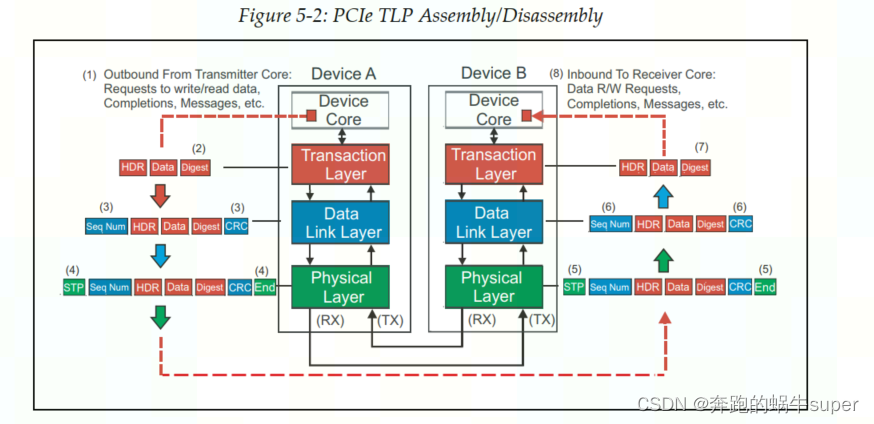
红色的是TLP的格式,Data是事务层上层给的数据,事务层给它头上加个Header,然后尾巴上再加个CRC校验(如果支持AER),就构成了一个TLP;这个TLP下传到数据链路层,又被数据链路层头上加了个包序列号,尾巴再加个CRC校验,构成一个DLLP;然后DLLP下传到物理层,头上加个Start,尾巴加个End符号,把这些数据分派到各个Lane上,然后每个Lane上加扰码,经8/10或128/130编码,最后通过物理传输介质传输给接收方。
接收方物理层是最先接收到这些数据的,然后执行逆操作;在数据链路层,校验序列号和LCRC,如果没错,剥掉序列号和LCRC,往事务层走;如果校验出差,通知对方重传;在事务层,校验ECRC,有错,数据抛弃,没错,去掉ECRC,获得数据。
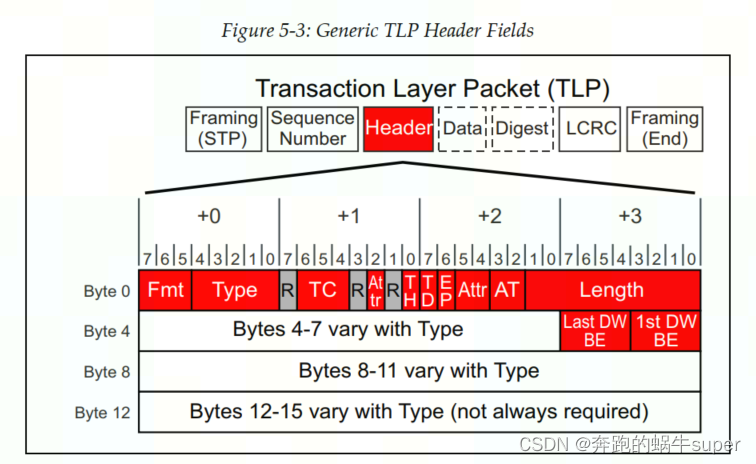
2.2 TLP Header Format
3. Specific TLP Formats: Request & Completion TLPs
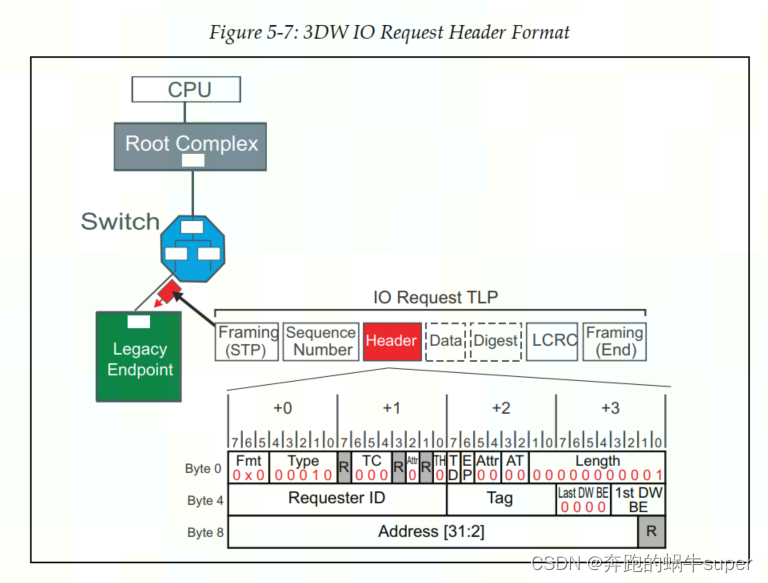
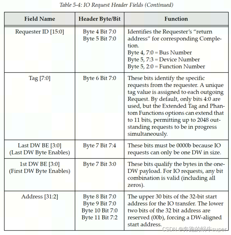
3.1 IO Requests
IO Request Header Format.
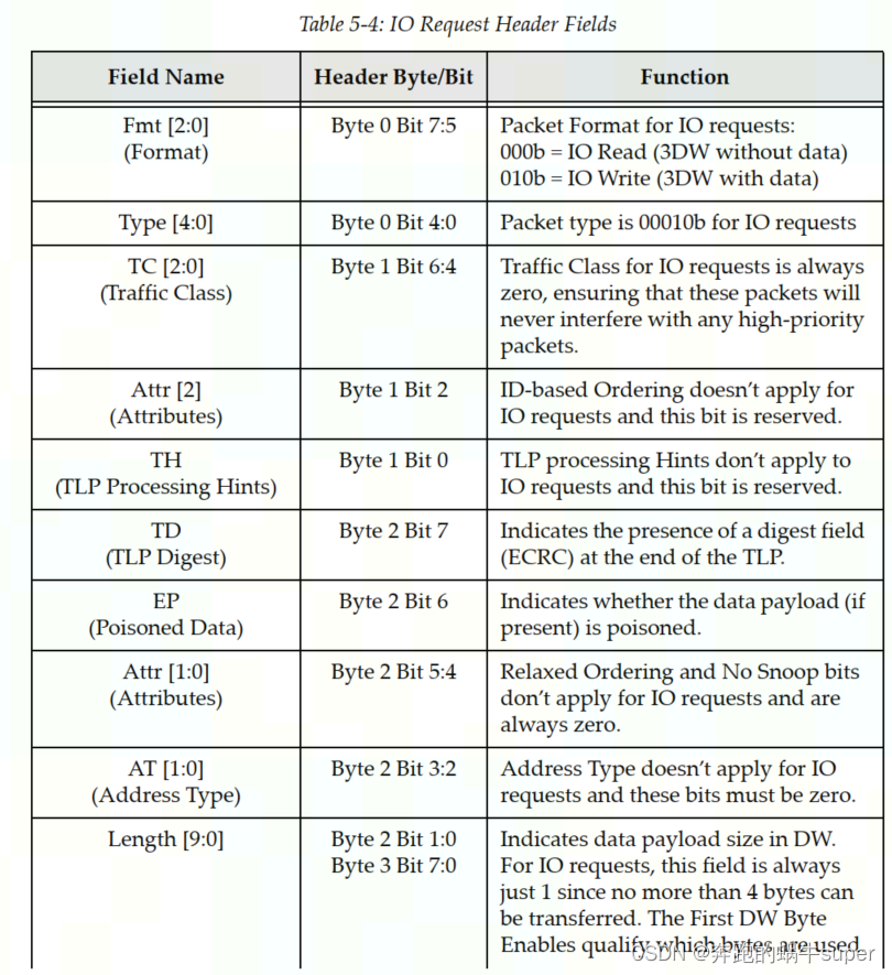
IO Request Header Fields
3.2 Memory Requests
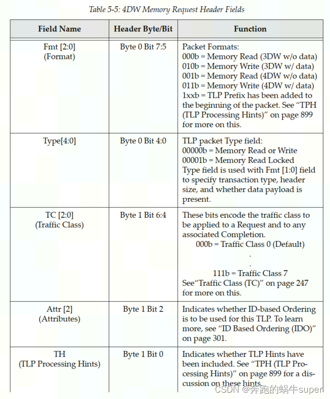
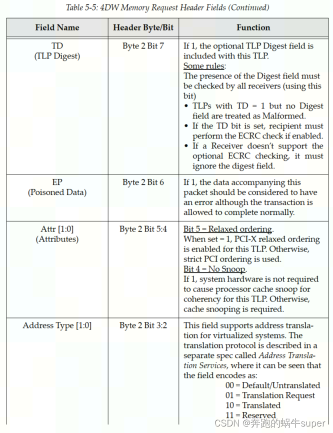
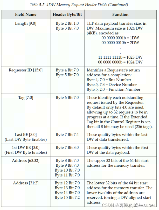
Memory Request Header Format.
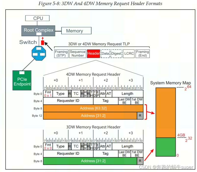
Memory Request Header Fields
内存请求注意事项。
内存请求的特性包括:
- Memory data transfers are not permitted to cross a 4KB boundary.
- All memory‐mapped writes are posted to improve performance.
- Either 32‐ or 64‐bit addressing may be used.
- Data payload size is between 0 and 1024 DW (0‐4KB).
- Quality of Service features may be used, including up to 8 Traffic Classes.
- The No Snoop attribute can be used to relieve the system of the need to
snoop processor caches when transactions target main memory. - The Relaxed Ordering attribute may be used to allow devices in the packet’s
path to apply the relaxed ordering rules in hopes of improving perfor‐
mance.
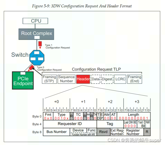
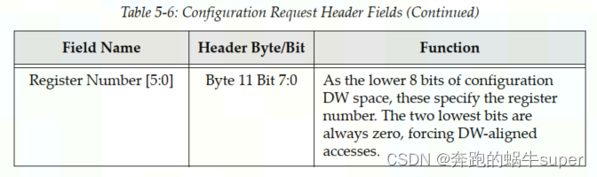
3.3 Configuration Requests
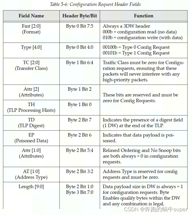
Configuration Request Header Format
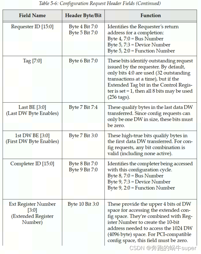
Definitions Of Configuration Request Header Fields.
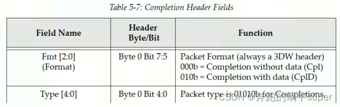
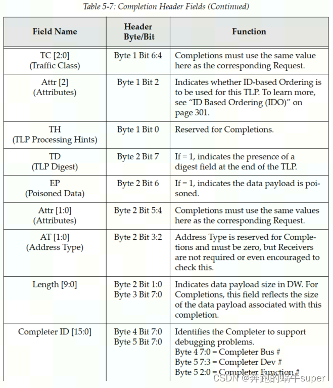
3.4 Completions
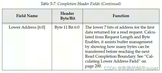
Completion Header Format

Definitions Of Completion Header Fields.
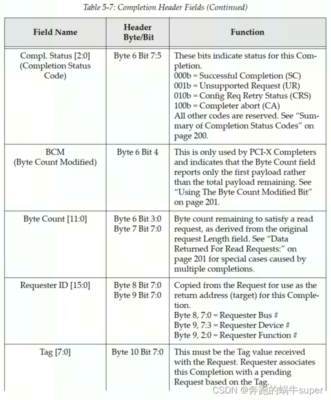
完成状态代码摘要。
•000b (SC)成功完成:请求得到了正确的处理。
•001b (UR)不支持的请求:请求不合法或未被完成者识别。
•010b (CRS)配置请求重试状态:完成程序暂时无法处理配置请求,请求应该稍后再尝试。
•100b (CA) Completer Abort:完成程序应该能够处理请求,但由于某种原因失败了。这是一个无法纠正的错误。
3.5 Message Requests
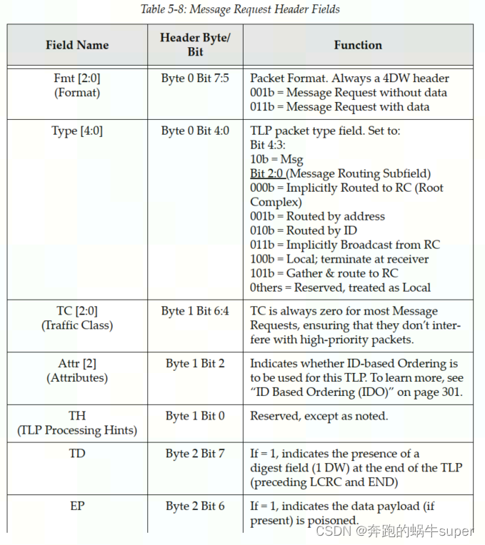
Message Request Header Format
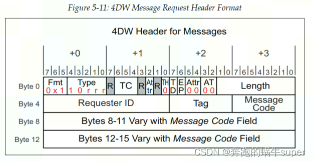
Message Request Header Fields.
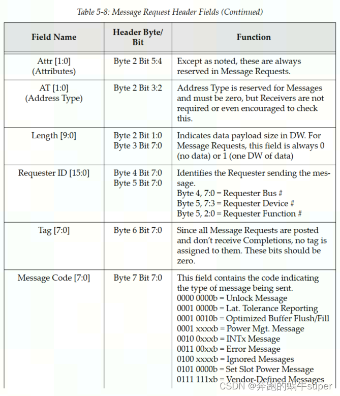

消息说明:表格指定了9个消息组中使用的消息编码,并基于表5‐8中列出的消息编码字段。定义的消息组包括:
- INTx Interrupt Signaling
- Power Management
- Error Signaling
- Locked Transaction Support
- Slot Power Limit Support
- Vendor‐Defined Messages
- Ignored Messages (related to Hot‐Plug support in spec revision 1.1)
- Latency Tolerance Reporting (LTR)
- Optimized Buffer Flush and Fill (OBFF)
3.5.1 INTx Interrupt Messages
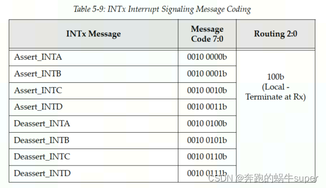
Rules regarding the use of INTx Messages:
- They have no data payload and so the Length field is reserved.
- They’re only issued by Upstream Ports. Checking this rule for received
packets is optional but, if checked, violations will be handled as Malformed
TLPs. - They’re required to use the default traffic class TC0. Receivers must check
for this and violations will be handled as Malformed TLPs. - Components at both ends of the Link must track the current state of the four
virtual interrupts. If the logical state of one interrupt changes at the
Upstream Port, it must send the appropriate INTx message. - INTx signaling is disabled when the Interrupt Disable bit of the Command
Register is set = 1 (as would be the case for physical interrupt lines). - If any virtual INTx signals are active when the Interrupt Disable bit is set in
the device, the Upstream Port must send corresponding Deassert_INTx
messages. - Switches must track the state of the four INTx signals independently for
each Downstream Port and combine the states for the Upstream Port. - The Root Complex must track the state of the four INTx lines indepen‐
dently and convert them into system interrupts in an implementation‐spe‐
cific way. - They use the routing type “Local‐Terminate at Receiver” to allow a Switch
to remap the designated interrupt pin when necessary (see “Mapping and
Collapsing INTx Messages” on page 808). Consequently, the Requester ID
in an INTx message may be assigned by the last transmitter
3.5.2 Power Management Messages.
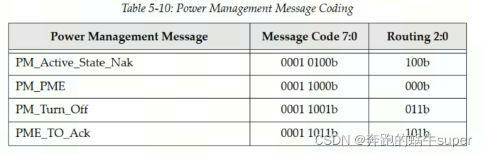
Power Management Message Rules:
- Power Management Messages don’t have a data payload, so the Length
field is reserved. - They’re required to use the default traffic class TC0. Receivers must check
for this and handle violations as Malformed TLPs. - PM_Active_State_Nak is sent from a Downstream Port after it observes a
request from the Link neighbor to change the Link power state to L1 but it
has chosen not to do so (Local ‐ Terminate at Receiver routing). - PM_PME is sent upstream by the component requesting a Power Manage‐
ment Event (Implicitly Routed to the Root Complex). - PM_Turn_Off is sent downstream to all endpoints (Implicitly Broadcast
from the Root Complex routing). - PME_TO_Ack is sent upstream by endpoints. For switches with multiple
Downstream Ports, this message won’t be forwarded upstream until all
Downstream Ports have received it (Gather and Route to the Root Complex
routing)
3.5.3 Error Messages
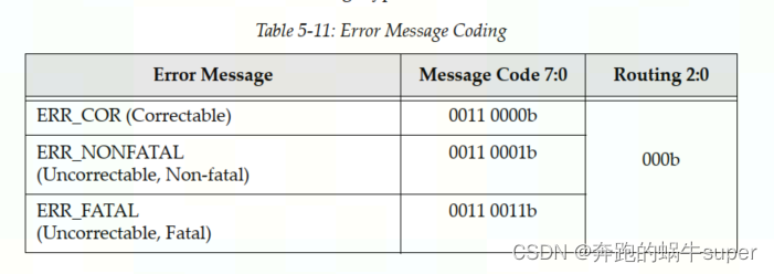
Error Signaling Message Rules:
- They’re required to use the default traffic class TC0. Receivers must check
for this and handle violations as Malformed TLPs. - They don’t have a data payload, so the Length field is reserved.
- The Root Complex converts Error Messages into system‐specific events.
3.5.4 Locked Transaction Support
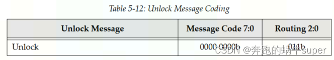
Unlock Message Rules:
- They’re required to use the default traffic class TC0. Receivers must check
for this and handle violations as Malformed TLPs. - They don’t have a data payload, and the Length field is reserved.
3.5.5 Set Slot Power Limit Message
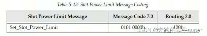
Set_Slot_Power_Limit Message Rules:
- They’re required to use the default traffic class TC0. Receivers must check
for this and handle violations as Malformed TLPs. - The data payload is 1 DW and so the Length field is set to one. Only the
lower 10 bits of the 32‐bit data payload are used for slot power scaling; the
upper payload bits must be set to zero. - This message is sent automatically anytime the Data Link Layer transitions
to DL_Up status or if a configuration write to the Slot Capabilities Register
occurs while the Data Link Layer is already reporting DL_Up status. - If the card in the slot already consumes less power than the power limit
specified, it’s allowed to ignore the Message.
3.5.6 Vendor‐Defined Message 0 and 1
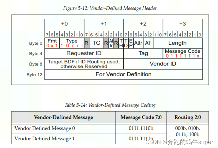
Vendor‐Defined Message Rules:
- A data payload may or may not be included with either type.
- Messages are distinguished by the Vendor ID field.
- Attribute bits [2] and [1:0] are not reserved.
- If the Receiver doesn’t recognize the Message:
• Type 1 Messages are silently discarded
• Type 0 Messages are treated as an Unsupported Request error condition
3.5.7 Ignored Messages
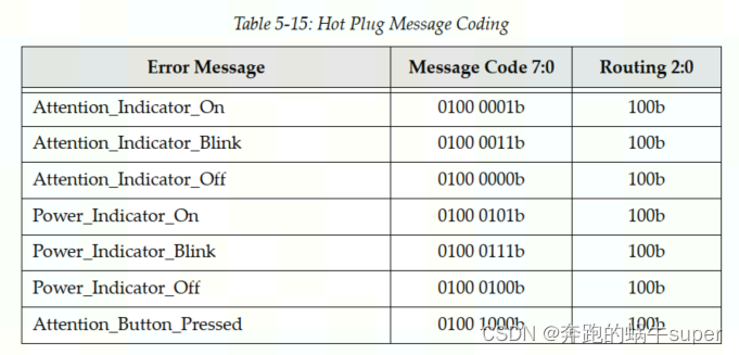
Hot Plug Message Rules:
• They are driven by a Downstream Port to the card in the slot.
• The Attention Button Message is driven upstream by a slot device.
3.5.8 Latency Tolerance Reporting Message
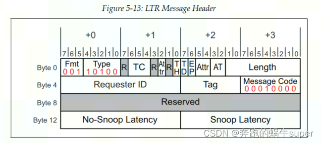
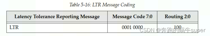
LTR Message Rules:
- They’re required to use the default traffic class TC0. Receivers must check
for this and handle violations as Malformed TLPs. - They don’t have a data payload, and the Length field is reserved.
3.5.9 Optimized Buffer Flush and Fill Messages

OBFF Message Rules:
- They’re required to use the default traffic class TC0. Receivers must check
for this and handle violations as Malformed TLPs. - They don’t have a data payload, and the Length field is reserved.
- The Requester ID must be set to the Transmitting Port’s ID.


 4302
4302

 被折叠的 条评论
为什么被折叠?
被折叠的 条评论
为什么被折叠?
 到【灌水乐园】发言


