


 本文详细介绍了5GNR中的Type II CSI码本,包括其与Type I的区别,如支持更高精度的线性组合、幅度和相位调整。针对rank 1和2,文章阐述了预编码矩阵的结构,以及如何从正交基中选择多个beam。同时,讨论了幅度调整(Wideband和Subband)和相位调整的比特分配,以及如何通过不同索引进行控制。最后,总结了Type II Codebook的主要特点和参数配置。
文章目录
5G NR Type II CSI Codebook简介
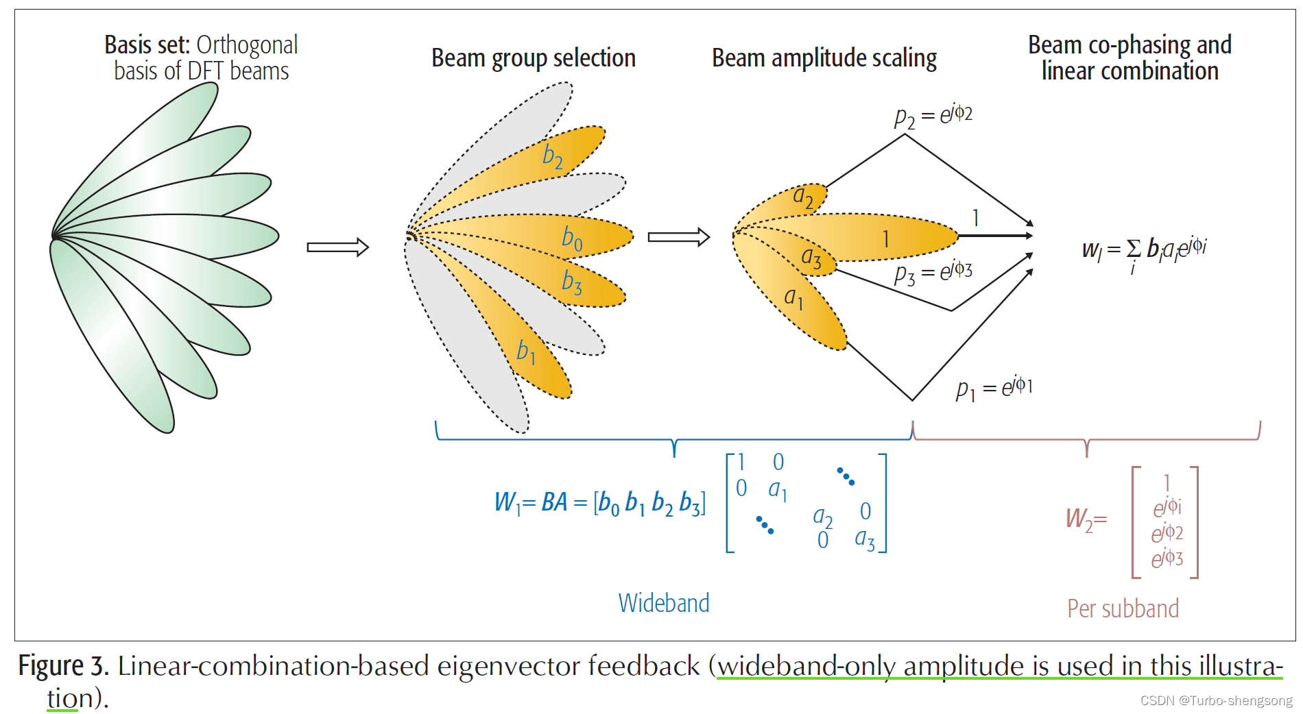
5G NR Type II Codebook相较于Type I Codebook拥有更高的复杂度和更高的精度。和LTE的Advanced CSI Codebook类似,都有做Linear Combination,但是LTE只从一群Beam Group中挑出两个彼此正交的beam来完成Linear Combination。而5G NR type II CSI Codebook则可以从一群Beam Group中挑选出2/3/4个彼此正交的Beam来完成Linear Combination。另外,除了挑选beam外,每个beam都会有一个对应的幅度和相位调整,幅度调整可以是Wideband与subband同时调整,也可以是Wideband单独调整,但是相位只能由subband调整。因此,更多的beam组合、整合幅度调整和相位调整,使得NR type II CSI Codebook拥有更高的复杂度和精度。
5G NR Type II CSI Codebook的一些基础限制
- 目前NR Type II CSI Codebook的layer数,即rank数最高只支持2。
- Linear Combination支持的Beam的数量为2/3/4,并且彼此正交。
- 幅度调整(Amplitude scaling)可以分为Wideband+Subband或Wideband only。
- 相位调整是在Subband上操作,相位的选择可以为QPSK(2bit)或者8-PSK(3bit)。
简单概述: NR Type II CSI for rank 1 and 2
⋅ \huge \cdot ⋅ PMI Codebook (PMI: Precoder Matrix Index)的两种预编码结构:
-
rank=1
W = [ w ~ 0 , 0 w ~ 1 , 0 ] = W 1 W 2 , W is normalized to 1 (1) \boldsymbol W = \left[ \begin{array}{c} \tilde \boldsymbol w_{0,0} \\ \tilde \boldsymbol w_{1,0} \\ \end{array} \right] = \boldsymbol W_1 \boldsymbol W_2, \ \ \boldsymbol W \text{ is normalized to 1} \tag{1} W=[w~0,0w~1,0]=W1W2, W is normalized to 1(1) -
rank=2
W = [ w ~ 0 , 0 w ~ 0 , 1 w ~ 1 , 0 w ~ 1 , 1 ] = W 1 W 2 , columns of W is normalized to 1 2 (2) \boldsymbol W = \left[ \begin{array}{c} &\tilde \boldsymbol w_{0,0} & \tilde \boldsymbol w_{0,1} \\ &\tilde \boldsymbol w_{1,0} & \tilde \boldsymbol w_{1,1} \\ \end{array} \right] = \boldsymbol W_1 \boldsymbol W_2, \ \ \text{columns of } \boldsymbol W \text{ is normalized to } \frac{1}{\sqrt 2} \tag{2} W=[w~0,0w~1,0w~0,1w~1,1]=W1W2, columns of W is normalized to 21(2)
⋅ \huge \cdot ⋅ Wighted Linear Combination of several beams
w ~ r , l = ∑ i = 0 L b k 1 ( i ) k 2 ( i ) ⋅ p r , l , i W B ⋅ p r , l , i S B ⋅ c r , l , i (3) \tilde \boldsymbol w_{r,l} = \sum_{i=0}^{L} \boldsymbol b_{k^{(i)}_1 k^{(i)}_2} \cdot p^{WB}_{r,l,i} \cdot p^{SB}_{r,l,i} \cdot c_{r,l,i} \tag{3} w~r,l=i=0∑Lbk1(i)k2(i)⋅pr,l,iWB⋅pr,l,iSB⋅cr,l,i(3)
\text{ } \ \ \text{ } 对上式的理解要注意以下几点:
-
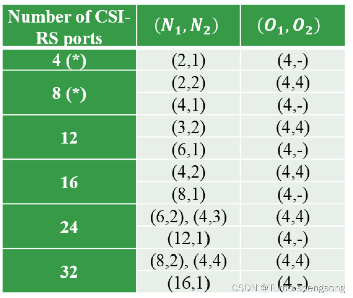
beam的数量 L L L是可以设置的: L ∈ { 2 , 3 , 4 } L \in \{2,3,4\} L∈{2,3,4}。注意,若令 N 1 N_1 N1为水平方向的双极化天线数,令 N 2 N_2 N2为竖直方向的双极化天线数,那么总的极化天线数为 P C S I − R S = 2 N 1 N 2 P_{CSI-RS}=2N_1N_2 PCSI−RS=2N1N2, P C S I − R S P_{CSI-RS} PCSI−RS与 L L L的关系为:
L = 2 when P C S I − R S = 4 L ∈ { 2 , 3 , 4 } when P C S I − R S > 4 (4) \begin{aligned} L=2 &\text{ when } P_{CSI-RS} = 4 \\ L\in\{2,3,4\} &\text{ when } P_{CSI-RS} > 4 \\ \end{aligned} \tag{4} L=2L∈{2,3,4} when PCSI−RS=4 when PCSI−RS>4(4) -
b k 1 ( i ) k 2 ( i ) \boldsymbol b_{k^{(i)}_1 k^{(i)}_2} bk1(i)k2(i)是过采样的2D DFT beam。
-
r = 0 , 1 r=0,1 r=0,1表示极化方向, l = 0 , 1 l=0,1 l=0,1表示第几个layer (rank),要注意区分 i i i 和 l l l , i i i表示第 i i i个beam, l l l表示rank。
-
p r , l , i W B p^{WB}_{r,l,i} pr,l,iWB : Wideband beam amplitude scaling factor for beam i i i on polarization r r r and layer l l l.
-
p r , l , i S B p^{SB}_{r,l,i} pr,l,iSB: Subband beam amplitude scaling factor for beam i i i on polarization r r r and layer l l l.
-
c r , l , i c_{r,l,i} cr,l,i: Beam combining coefficient (phase) for beam i i i on polarization r r r and layer l l l. 可以设置为QPSK(2 bit)或者8-PSK(3 bit)。
补充一点,式(3)可以看出, L L L个DFT beam与polarization r r r 无关,与layer l l l 也无关,选定的beam是什么就用什么,幅度、相位等等再具体做调整。另外,这里我还想强调一点,但这只是我的理解,读者感兴趣的话可以想一想。一般地,矩阵 W 1 \boldsymbol W_1 W1表示信道的 long-term frequency-independent characteristics,字面上不太好看出来,但是我理解的就是该通信系统所处的信道环境,比如反射、散射物的位置在较长时间内认为不发生变化,那么根据实际的物理环境,我们认为在这较长的时间范围,从发送端打出去的beam,在方向上几乎是保持不变的。
这里给出一个示例,多个beam的线性组合反馈,包括幅度调整(WB Only)和相位调整
Wideband中的Beam选取(Wideband Only)
这部分我们将说明如何从Beam Group中挑选出 L L L 个正交的Beam,挑选出来的这些beam的索引由 i 11 i_{11} i11和 i 1 , 2 i_{1,2} i1,2决定:
- i 11 i_{11} i11: 决定Beam Group中哪些Beam是正交的
- i 12 i_{12} i12: 从 i 11 i_{11} i11所决定的那些彼此正交的Beam中挑选出 L L L个
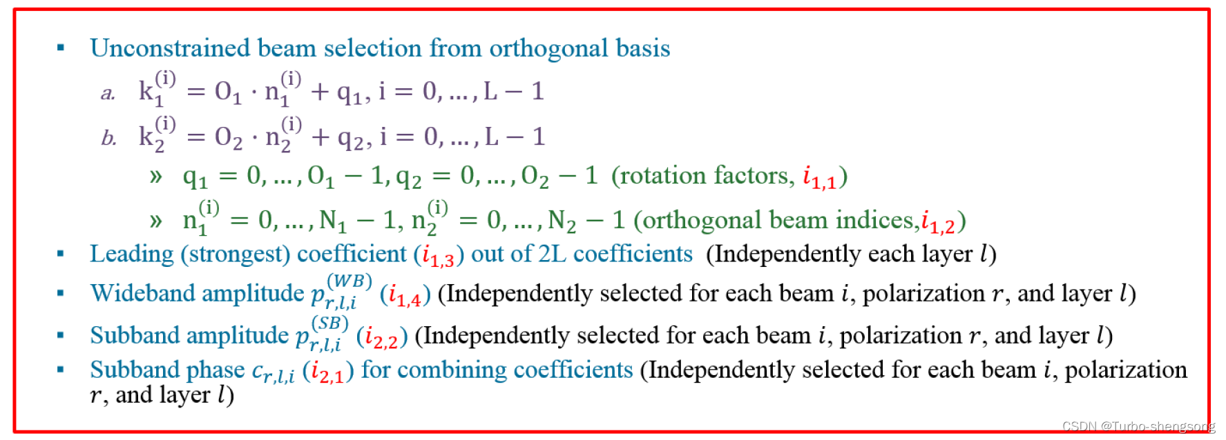
Unconstrained beam selection from the orthogonal basis
我们先给出一个oversampled DFT beam的例子,令
O
1
,
O
2
O_1, O_2
O1,O2分别为水平、竖直方向的过采样数,下图是一个
(
N
1
,
N
2
,
O
1
,
O
2
)
=
(
2
,
2
,
4
,
4
)
(N_1, N_2, O_1, O_2) = (2, 2, 4, 4)
(N1,N2,O1,O2)=(2,2,4,4)的例子
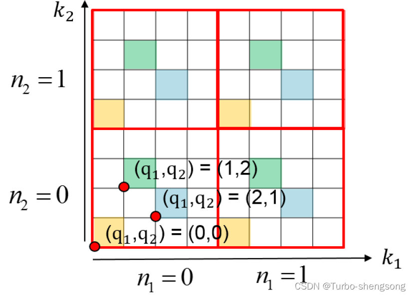
图中黄色的四个方格表示4个正交的beam, k 1 , k 2 k_1,k_2 k1,k2分别表示水平和竖直方向上的beam索引(坐标),我们对图中的一些参数做具体的解释
-
水平方向的Beam索引 ( 1 s t 1^{st} 1st dimension)
水平方向的Beam索引我们用 k i ( 1 ) k^{(1)}_i ki(1)表征,表示所选取的第 i i i个beam的横坐标,具体可写为
k i ( 1 ) = O 1 ⋅ n 1 ( i ) + q 1 , i = 0 , ⋯ , L − 1 (5) k^{(1)}_i = O_1 \cdot n^{(i)}_1 + q_1, \ \ i=0,\cdots,L-1 \tag{5} ki(1)=O1⋅n1(i)+q1, i=0,⋯,L−1(5) -
竖直方向的Beam索引 ( 2 n d 2^{nd} 2nd dimension)
竖直方向的Beam索引我们用 k i ( 2 ) k^{(2)}_i ki(2)表征,表示所选取的第 i i i个beam的纵坐标,具体可写为
k i ( 2 ) = O 2 ⋅ n 2 ( i ) + q 2 , i = 0 , ⋯ , L − 1 (6) k^{(2)}_i = O_2 \cdot n^{(i)}_2 + q_2, \ \ i=0,\cdots,L-1 \tag{6} ki(2)=O2⋅n2(i)+q2, i=0,⋯,L−1(6)
进一步,我们对参数 n 1 , n 2 n_1, n_2 n1,n2和 q 1 , q 2 q_1, q_2 q1,q2做具体解释。
首先,我们要明确,当我们确定相关的天线数
N
1
,
N
2
N_1,N_2
N1,N2时,我们实际上就已经可以确定(知道)一组正交的DFT beams,实际上就是图中黄色的4个beam,可以理解为最基本的4个正交beam,这也意味着,我们可以把
n
1
(
i
)
.
n
2
(
i
)
n^{(i)}_1.n^{(i)}_2
n1(i).n2(i)理解为是基准的正交beam的索引,由
i
12
i_{12}
i12 表征,
n
1
(
i
)
=
0
,
⋯
,
N
1
−
1
;
n
2
(
i
)
=
0
,
⋯
,
N
2
−
1.
(
orthogonal beam indices,
i
12
)
(7)
n^{(i)}_1 = 0, \cdots, N_1-1; \ \ n^{(i)}_2 = 0, \cdots, N_2-1. \ \ ( \text{orthogonal beam indices, } i_{12}) \tag{7}
n1(i)=0,⋯,N1−1; n2(i)=0,⋯,N2−1. (orthogonal beam indices, i12)(7)
然后,当我们理解基准正交DFT beams后,我们再来看参数
q
1
,
q
2
q_1, q_2
q1,q2,这两个参数的理解相对比较简单,由上图可以知道,它们所表征的就是基准正交DFT beams的旋转(rotation),
q
1
q_1
q1表示水平方向beam的旋转,
q
2
q_2
q2表示竖直方向beam的旋转,具体为
q
1
=
0
,
⋯
,
O
1
−
1
;
q
2
=
0
,
⋯
O
2
−
1.
(
rotation factors
,
i
11
)
(8)
q_1 = 0,\cdots,O_1-1; \ \ q_2 = 0,\cdots O_2 - 1. \ \ (\text{rotation factors}, i_{11}) \tag{8}
q1=0,⋯,O1−1; q2=0,⋯O2−1. (rotation factors,i11)(8)
这里给出 ( N 1 , N 2 ) (N_1,N_2) (N1,N2)和 ( O 1 , O 2 ) (O_1,O_2) (O1,O2)的一些参数配置
每个Beam的幅度和相位反馈
决定一组正交的Beam之后,我们再来决定每个Beam的幅度和相位,我们分别对幅度调整和相位调整的索引进行说明:
-
幅度调整对应的索引
(1) Wideband Amplitude: i 14 i_{14} i14表征宽带幅度调整的索引,独立于每个Beam、每个Polarization与layer,每个 i 14 i_{14} i14有8种选择(对应3个bit)。这8种幅度可取的集合为:
{ 1 , 1 2 , 1 4 , 1 8 , 1 1 6 , 1 3 2 , 1 6 4 , 0 } (9) \{1, \frac{1}{\sqrt 2}, \frac{1}{\sqrt 4}, \frac{1}{\sqrt 8}, \frac{1}{\sqrt 16}, \frac{1}{\sqrt 32}, \frac{1}{\sqrt 64}, 0 \} \tag{9} {1,21,41,81,161,321,641,0}(9)(2) Subband Amplititude: i 22 i_{22} i22表征子带上幅度调整的索引,独立于每个Beam、每个Polarization与layer,每个 i 2 i_{2} i2有2种选择(对应1个bit)。这2种幅度可取的集合为:
{ 1 , 1 2 } (10) \{1, \frac{1}{\sqrt 2}\} \tag{10} {1,21}(10) -
相位调整对应的索引
subband phase: i 21 i_{21} i21: 表征子带上相位调整的索引,独立于每个Beam、每个Polarization与layer,可分为8-PSK(3 bit)和QPSK(2 bit)。
QPSK: { e j π n 2 , n = 0 , 1 , 2 , 3 } 8-PSK: { e j π n 4 , n = 0 , 1 , ⋯ , 7 } (11) \begin{aligned} \text{QPSK: } &\{e^{j \frac{\pi n}{2}}, \ n=0,1,2,3\} \\ \text{8-PSK: } & \{ e^{j\frac{\pi n}{4}} , \ n=0,1,\cdots,7 \} \end{aligned} \tag{11} QPSK: 8-PSK: {ej2πn, n=0,1,2,3}{ej4πn, n=0,1,⋯,7}(11)
上面所提及的“独立于每个Beam、每个Polarization与layer”是指系统要分别独立地为每个beam i i i,每个polarization r r r, 每个layer l l l 提供幅度和相位,并且不同的 ( r , l , i ) (r,l,i) (r,l,i)所对应的幅度或相位值都可能不一样,相互之间没有联系。
另外,我们还要补充一个索引
i
13
i_{13}
i13: 2L个beam中(这里说2L个beam是考虑双极化天线)最强的beam,该beam的所有系数,包括幅度和相位都为1。
幅度和相位调整的比特分配
我们把(Wideband amplitude: i 14 i_{14} i14, Subband amplitude: i 22 i_{22} i22, Subband phase: i 21 i_{21} i21)量化为 ( X , Y , Z ) (X, Y, Z) (X,Y,Z) bits的形式(这里指多少个bit)
-
注意,对每一个 layer,the leading (strongest) coefficient ( i 13 i_{13} i13)对应于所有 2 L 2L 2L个beams中最强的beam,事实上,对于这个beam,并不需要额外反馈什么,因为我们知道它所对应的系数为1。即
( X , Y , Z ) = ( 0 , 0 , 0 ) The leading (strongest) coefficient = 1 \begin{aligned} (X, Y, Z) = (0, 0, 0) \\ \text{ The leading (strongest) coefficient } = 1 \end{aligned} (X,Y,Z)=(0,0,0) The leading (strongest) coefficient =1 -
WB+SB amplitude
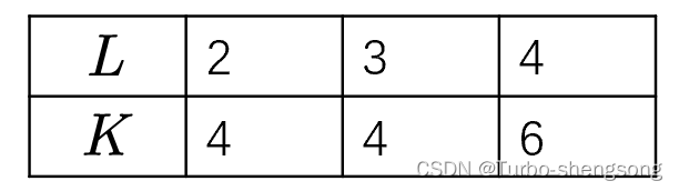
( X , Y ) = ( 3 , 1 ) (X,Y)=(3,1) (X,Y)=(3,1) and Z ∈ { 2 , 3 } Z \in \{2, 3\} Z∈{2,3} for the first [ min ( K − 1 , M l ) ] [\min(K-1, M_l)] [min(K−1,Ml)] leading (strongest) coefficients out of ( 2 L − 1 ) (2L-1) (2L−1) coefficients, and ( X , Y , Z ) = ( 3 , 0 , 2 ) (X, Y, Z) = (3, 0, 2) (X,Y,Z)=(3,0,2) for the remaining [ 2 L − min ( K , M l + 1 ) ] [2L - \min(K,M_l+1)] [2L−min(K,Ml+1)] coefficients.其中, M l M_l Ml is the number of elements of i 14 i_{14} i14 that satisfy i 14 > 0 i_{14} > 0 i14>0;
K K K和 L L L的对应关系如下图所示
- WB-Only amplitude, i.e.
Y
=
0
Y=0
Y=0
( X , Y ) = ( 3 , 0 ) and Z ∈ { 2 , 3 } (X,Y) = (3,0) \text{ and } Z \in \{2,3\} (X,Y)=(3,0) and Z∈{2,3}
PMI Indices小结
-
一般认为PMI Codebook具有下面两种结构
(1) rank=1
W = [ w ~ 0 , 0 w ~ 1 , 0 ] = W 1 W 2 , W is normalized to 1 \boldsymbol W = \left[ \begin{array}{c} \tilde \boldsymbol w_{0,0} \\ \tilde \boldsymbol w_{1,0} \\ \end{array} \right] = \boldsymbol W_1 \boldsymbol W_2, \ \ \boldsymbol W \text{ is normalized to 1} W=[w~0,0w~1,0]=W1W2, W is normalized to 1(2) rank=2
W = [ w ~ 0 , 0 w ~ 0 , 1 w ~ 1 , 0 w ~ 1 , 1 ] = W 1 W 2 , columns of W is normalized to 1 2 \boldsymbol W = \left[ \begin{array}{c} &\tilde \boldsymbol w_{0,0} & \tilde \boldsymbol w_{0,1} \\ &\tilde \boldsymbol w_{1,0} & \tilde \boldsymbol w_{1,1} \\ \end{array} \right] = \boldsymbol W_1 \boldsymbol W_2, \ \ \text{columns of } \boldsymbol W \text{ is normalized to } \frac{1}{\sqrt 2} W=[w~0,0w~1,0w~0,1w~1,1]=W1W2, columns of W is normalized to 21 -
上式所描述的分块向量 w ~ r , l \tilde \boldsymbol w_{r,l} w~r,l可以表示为下面加权线性组合的形式
w ~ r , l = ∑ i = 0 L b k 1 ( i ) k 2 ( i ) ⋅ p r , l , i W B ⋅ p r , l , i S B ⋅ c r , l , i wighted combination of L beams \tilde \boldsymbol w_{r,l} = \sum_{i=0}^{L} \boldsymbol b_{k^{(i)}_1 k^{(i)}_2} \cdot p^{WB}_{r,l,i} \cdot p^{SB}_{r,l,i} \cdot c_{r,l,i} \ \ \text{wighted combination of L beams} w~r,l=i=0∑Lbk1(i)k2(i)⋅pr,l,iWB⋅pr,l,iSB⋅cr,l,i wighted combination of L beams -
索引的描述
上图中,我们可以把 ( k 1 ( i ) , k 2 ( i ) ) (k^{(i)}_1, k^{(i)}_2) (k1(i),k2(i))理解为是beam的横纵坐标。
Type II Codebook小结
- 使用beam的数量
- L = 2 , 3 , 4 L=2,3,4 L=2,3,4 对应到(Number of strongest beam K=4,4,6,注意这里有考虑到双极化)
- 幅度调整
- WB+SB: SB have 2 selections for the strongest min ( K − 1 , M l ) \min(K-1, M_l) min(K−1,Ml) (1bit) beams, and one selection for the remaining 2 L − min ( K , M l + 1 ) 2L -\min(K, M_l+1) 2L−min(K,Ml+1) beams (0 bit).
- WB only
(Note: W l W_l Wl is the number of elements of i 14 i_{14} i14 (Wideband amplitude) that satisfy i 14 ≥ 0 i_{14} \geq 0 i14≥0 )
- 相位调整
- 8-PSK: for the strongest min ( K − 1 , M l ) \min(K-1, M_l) min(K−1,Ml) (3bit) beams, and QPSK for the remaining 2 L − min ( K , M l + 1 ) 2L -\min(K, M_l+1) 2L−min(K,Ml+1) beams (2 bit).
- QPSK
- 支持的layer数
- #. layer = 1,2
参考
[1] https://www.commresearch.com.tw/Blog/ViewArticle.aspx?guid=28dd1d3f-0f06-4566-8d29-e0e1c9f79c25
[2] http://www.sharetechnote.com/html/5G/5G_CSI_RS_Codebook.html#What_is_Codebook
[3] E. Onggosanusi et al., “Modular and High-Resolution Channel State Information and Beam Management for 5G New Radio,” in IEEE Communications Magazine, vol. 56, no. 3, pp. 48-55, March 2018, doi: 10.1109/MCOM.2018.1700761.


 4658
4658

 被折叠的 条评论
为什么被折叠?
被折叠的 条评论
为什么被折叠?
 到【灌水乐园】发言


