


一、设置 arduino 编辑器
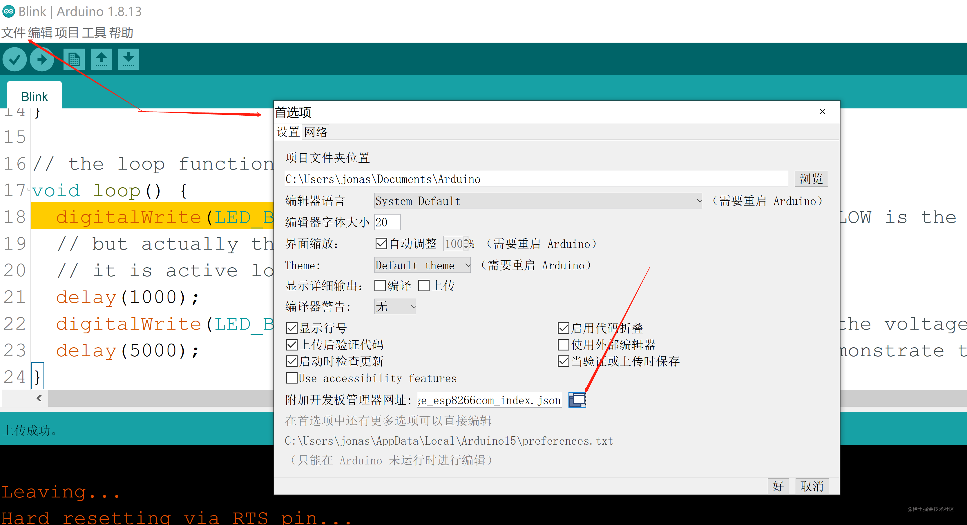
1、文件-首选项-附加开发版管理网址中添加
http://arduino.esp8266.com/stable/package_esp8266com_index.json
2、工具-开发板管理
搜索 8266 并下载
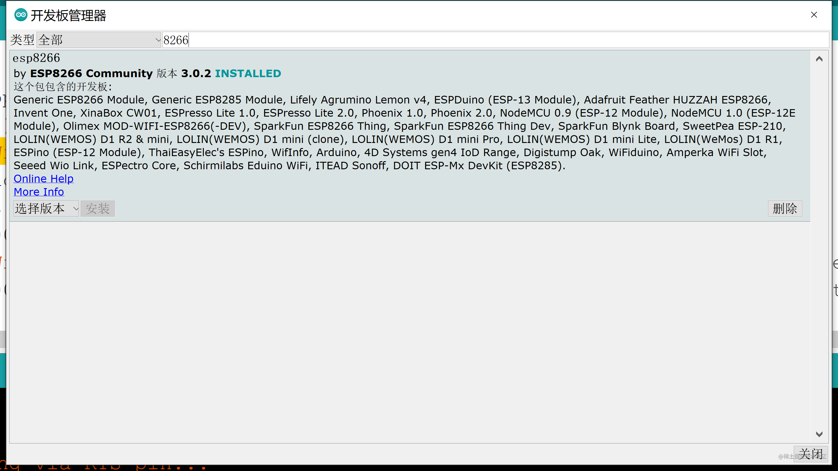
)
3、工具-开发板
在 8266 里面选择 Generic ESP8266 Module
4、工具-端口
记得选择对应的端口
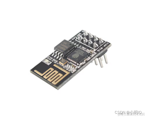
二、接线
必须按照下图规定接线(GPIO2 可以不用接),
VCC(3.3V) 先不接
GND 接 GND
TX 接 RX
RX 接 TX
其余的按下表
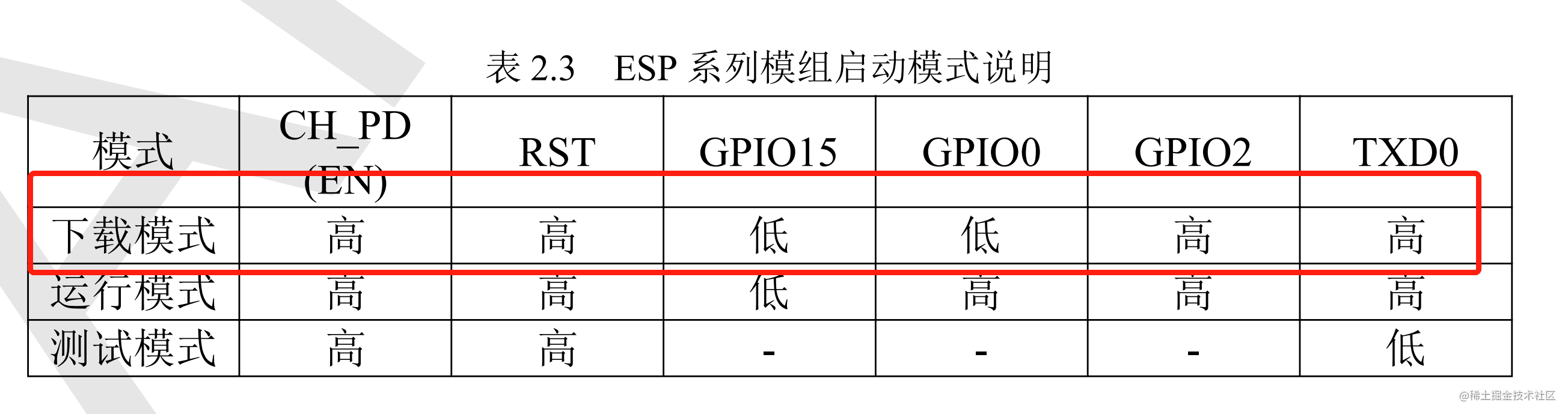
三、上传
在usb转串口工具连接到电脑 USB 之前,必须吧 vcc 先断开。
然后把转串口工具连接上 usb,然后上传代码,在下图时候才可插入 VCC
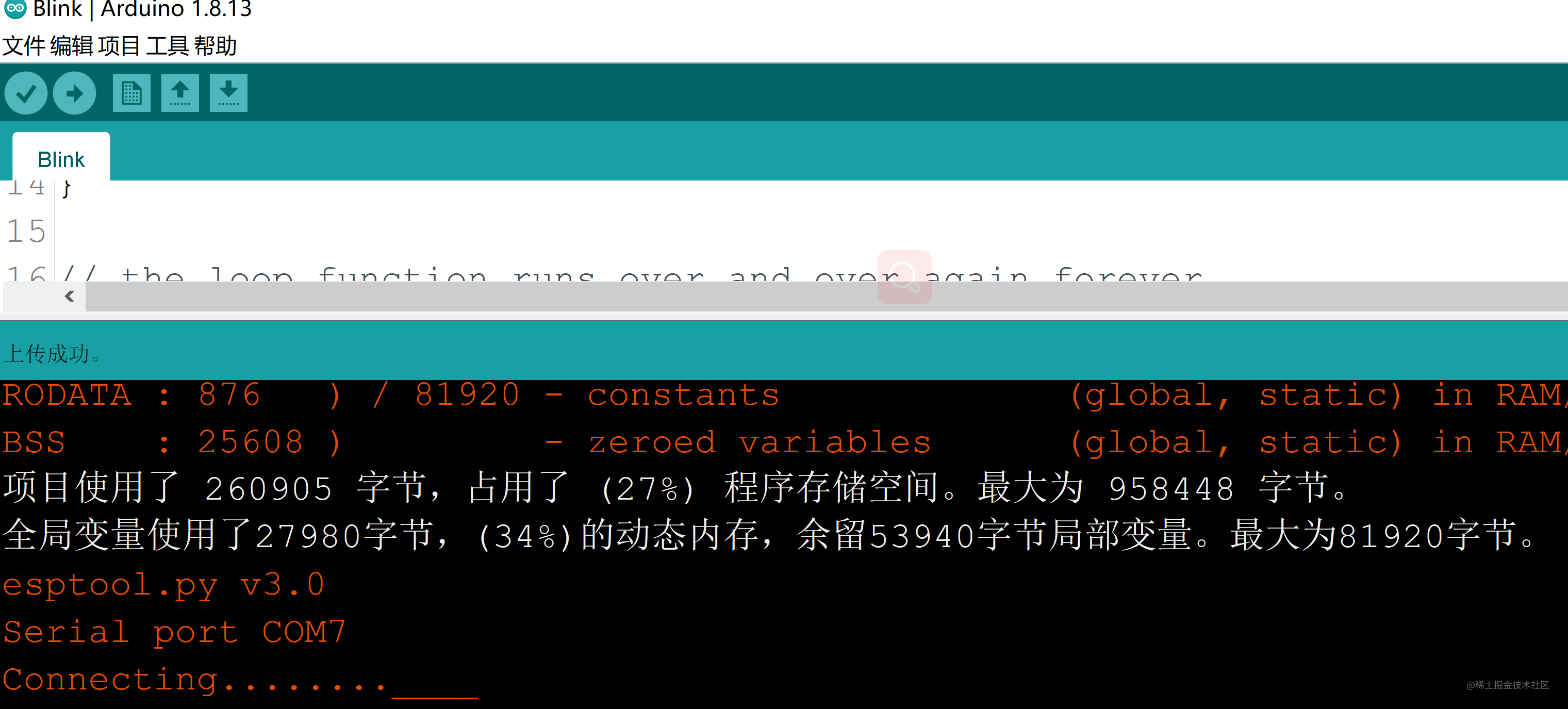
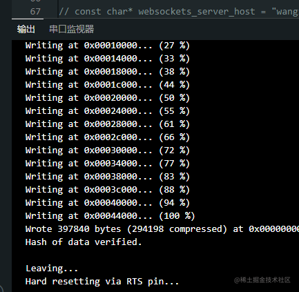
输出如下则上传代码完毕
四、运行板子
1、拔掉 USB 转串口工具提供的 3.3v 电压
2、将 GPIO0 引脚插入接入到高电平
3、插入USB 转串口工具提供的 3.3v 电压即可看到串口监视器开始输出了
4、从别的电源模块引用一个稳定的 3.3v 电压(比如 arduino 提供的 3.3v), 否则可能启动板子就报错
5、共地,别的电源的 GND 引脚要和 usb转串口工具的 GDN 引脚接到一起(否则串口工具输出是乱码)
五、测试代码
可以烧录实例程序中的 Blink 案例测试,代码如下
/*
  ESP8266 Blink by Simon Peter
  Blink the blue LED on the ESP-01 module
  This example code is in the public domain

  The blue LED on the ESP-01 module is connected to GPIO1
  (which is also the TXD pin; so we cannot use Serial.print() at the same time)

  Note that this sketch uses LED_BUILTIN to find the pin with the internal LED
*/

void setup() {
  Serial.begin(9600);
  pinMode(LED_BUILTIN, OUTPUT);     // Initialize the LED_BUILTIN pin as an output
}

// the loop function runs over and over again forever
void loop() {
  Serial.print("hello \n ");
  digitalWrite(LED_BUILTIN, LOW);   // Turn the LED on (Note that LOW is the voltage level
  // but actually the LED is on; this is because
  // it is active low on the ESP-01)
  delay(1000);                      // Wait for a second
  digitalWrite(LED_BUILTIN, HIGH);  // Turn the LED off by making the voltage HIGH
  delay(5000);                      // Wait for two seconds (to demonstrate the active low LED)
}
烧录完成后 把 arduino 板子的 3.3v 和 GND 连接到 esp01s 板子即可看到 5s 的间隔灯会闪一下
四、常见报错
1、A fatal esptool.py error occurred: Cannot configure port. PermissionError(13, ‘A device attached to the system is not functioning.’, None, 31
驱动问题,下载老版本即可,一般只是 D1 板子在 win11 会出这个问题
下载地址: https://electropeak.com/learn/download/ch341ser-zip/# ,注意:一定要下载这个压缩包这个 ch341ser-zip
注意:重新安装驱动前先关闭 arduino ide
2、A fatal esptool.py error occurred: Cannot configure port, something went wrong. Original message: PermissionError(13, ‘�ܾ����ʡ�’, None, 5)
可能是电脑 usb 插了多个扩展坞冲突了,都拔了试试,排查几天才发现出来的。
一些其他异常
参考:https://links2004.github.io/Arduino/dc/deb/md_esp8266_doc_exception_causes.html
3、ets Jan 8 2013,rst cause:4, boot mode:(3,2)
反正就是一堆这种提示stack>>>
3fffff20: 40226457 d334fe18 4021024c 3ffed430
3fffff30: 3fff256c 00000001 40226496 40210265
3fffff40: 402262a5 3fff2794 3fffff80 3fff1dac
3fffff50: 3ffe0000 3fff256c 3ffef780 40226c94
3fffff60: 3fff2794 3fff1dac 3ffeaf26 402259f7
3fffff70: 3fff1dac 00000014 40225fa2 3fff2794
3fffff80: 3fff1dac 3fffdc80 3fff1e14 3fff0460
3fffff90: 4021d93b 3fff2794 00000000 4020767f
3fffffa0: 40000f49 3fffdab0 3fffdab0 40000f49
<<<stack<<<
也是排查几天才解决…
上传完毕代码后,将 vcc 和 gnd 插入到别的稳定电源,比如 arduino 上面。rx 和 tx 保持不变就可以继续调试串口了。


 798
798

 被折叠的 条评论
为什么被折叠?
被折叠的 条评论
为什么被折叠?
 到【灌水乐园】发言


