CANBUS介绍

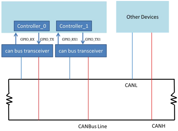
控制器区域网路 (Controller Area Network),允许网路上的多个微控制器或设备直接互相通讯,

且网路上不需要主机(Host)控制通讯。Canbus 具有高扩充性、高可靠度且低成本等特性,同一

个线上的装置必需有相同的 baud rate 才可通讯,其基础网路架构图如下图。
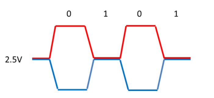
Canbus 讯号介绍:

CANBUS 在传输显性(0)讯号时,会将 CANH 端抬向 5V 高电位,将 CANL 拉向 0V 低电位。

当传输隐性(1)讯号时,并不会驱动 CANH 或者 CANL 端,如下图。

Canbus frame 介绍:

Canbus 通讯以一个 frame 为一个单位,而 CAN 2.0B 有 4 种 frame 类型。

类型

用途

资料frame

传输的节点资料的 frame

远端 frame(RTR)

请求传输特定识别码的 frame

错误 frame

检测到错误的节点传送的 frame

过载 frame

资料框或远端 frame 之间插入延迟的 frame

其中资料 frame (data frame)为使用者最需要自行设定的类型,它有两种资讯结构:

类型(IDE)

支援 ID bits

基本 frame 格式(STD frame)

11

扩充 frame 格式(EXT frame)

29

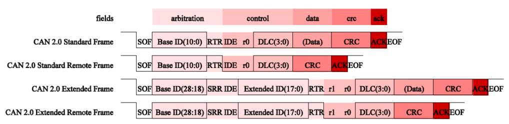
基本 frame 格式说明(CAN 2.0 standard frame):

栏位

位元数

说明

SOF

1

表示 frame 的传输起点

BASE ID

11

辨识码(ID),也带有传输优先级涵义

RTR

1

远端请求 frame 设定,资料框设(0),远端请求 frame 设(1)

IDE

1

基本 frame 设(0)

R0

1

预留位

DLC

4

资料的位元组数

Data

Data

待传输资料(长度由资料长度码 DLC 指定)

CRC

16

CRC 错误检查

ACK

2

发信端传送(1)但是任何接收端可以设(0)

EOF

7

表示 frame 结束必为(1)

扩充 frame 格式(CAN 2.0 extended frame):

栏位

位元数

说明

SOF

1

表示 frame 的传输起点

BASE ID

11

辨识码(ID),也带有传输优先级涵义

SRR

1

替代远端请求,必为(1)

IDE

1

扩充 frame 设(1)

Extended ID

18

第二部分辨识码(ID),同 BASE ID 带有传输优先级涵义

RTR

1

远端请求 frame 设定,资料框设(0),远端请求 frame 设(1)

R0

1

预留位

DLC

4

资料的位元组数

Data

0-64

待传输资料(长度由资料长度码 DLC 指定)

CRC

16

CRC 错误检查

ACK

2

发信端传送(1)但是任何接收端可以设(0)

EOF

7

表示 frame 结束必为(1)

DLC(Data Length Code)转换表:

DLC

bytes

0x0000

0

0x0001

1

0x0010

2

0x0011

3

0x0100

4

0x0101

5

0x0110

6

0x0111

7

0x1000

8

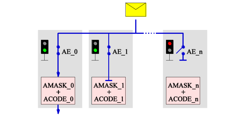
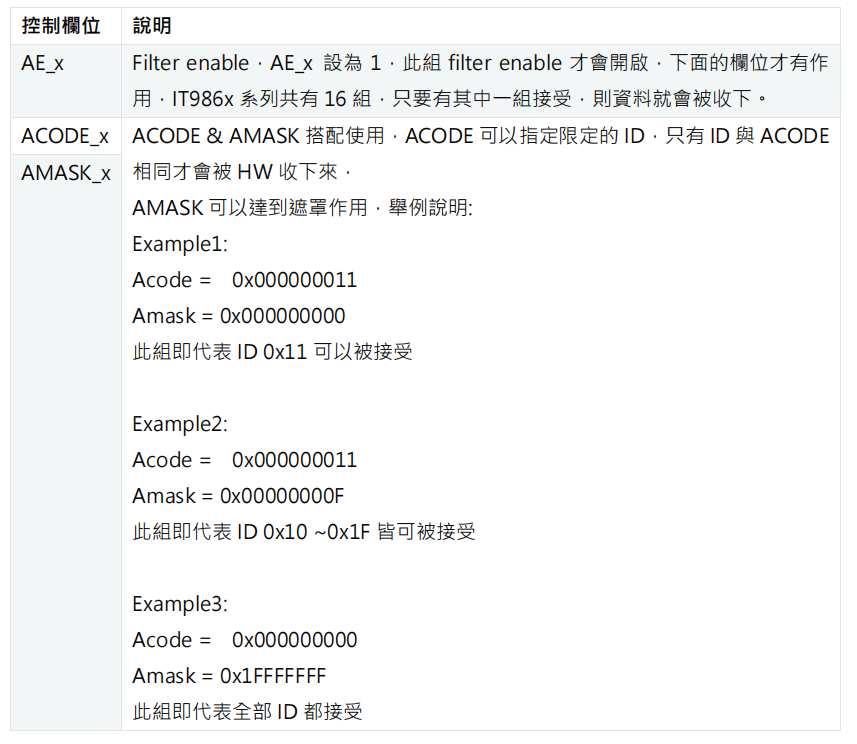
Canbus ID filtering 介紹:

Canbus 在传送资料的过程是类似广播的方式进行,所以在装置数量众多的时候,单一装置会收

到所有装置所传出的各种资料,但其实只要接收与它有相关的资料即可,所以在接收端就需要 ID

filter 来过滤资料,好处是可以降低装置处理资料的负担,下图为 filter 作用的示意图。
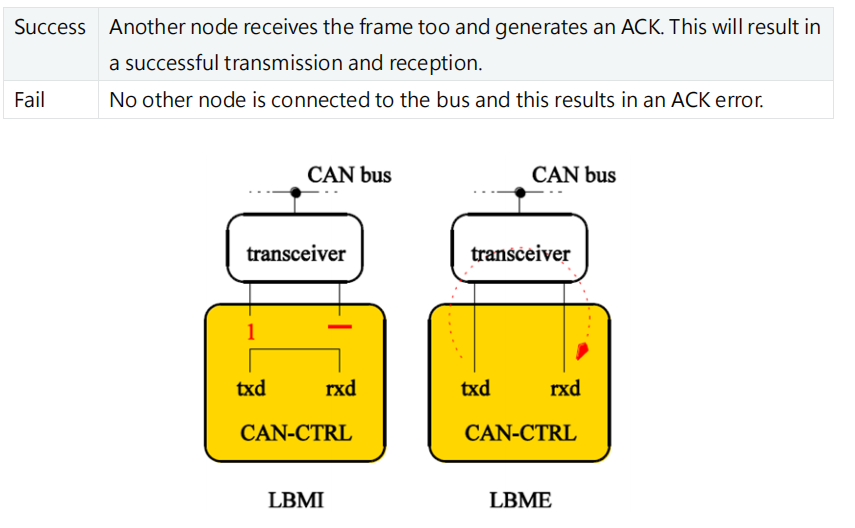
Canbus Debug 模式介紹:

IT986x支持两种Loop Back mode: internal (LBMI)和external (LBME)。两种模式都会接收到自己传输的帧,这对自检很有用。

在LBMI从CAN总线断开,txd输出被设置为隐性。输出数据流在内部反馈给输入。

在LBME中,保持与收发器的连接,传输的帧将在总线上可见。因此,在SACK=0的LBME中,帧传输有两种可能的结果:

CANBus数据链路层协议采用对等式(Peer to peer)通信方式,即使主机出现故障,系统其余部分仍可运行(当然性能受一定影响)。当一个站点状态改变时,它可广播发送信息到所有站点。 CANBus的信息传输通过报文进行,报文帧有4种类型:数据帧、远程帧、出错帧超载帧,其中数据帧格式如图8所示。CANBus帧的数据场较短,小于8B,数据长度在控制场中给出。短帧发送一方面降低了报文出错率,同时也有利于减少其他站点的发送延迟时间。帧发送的确认由发送站与接收站共同完成,发送站发出的ACK场包含两个“空闲”位(recessive bit),接收站在收到正确的CRC场后,立即发送一个“占有”位(dominant bit),给发送站一个确认的回答。CANBus还提供很强的错误处理能力,可区分位错误、填充错误、CRC错误、形式错误应答错误等。 CANBus应用一种面向位型的损伤仲裁方法来解决媒体多路访问带来的冲突问题。其仲裁过程是:当总线空闲时,线路表现为“闲置”电平(recessive level),此时任何站均可发送报文。发送站发出的帧起始字段产生一个“占有”电平(dominant level),标志发送开始。所有站以首先开始发送站的帧起始前沿来同步。若有多个站同时发送,那么在发送的仲裁场进行逐位比较。仲裁场包含标识符ID(标准为llbit),对应其优先级。每个站在发送仲裁场时,将发送位与线路电平比较,若相同则发送;若不同则得知优先级低而退出仲裁, 不再发送。系统响应时间与站点数无关,只取决于安排的优先权。可以看出,这种媒体访问控制方式不像Ethetnet的CSMA/CDCA协议那样会造成数据与信道带宽受损。
The Controller Area Network (CAN) is a serial communications protocol which efficiently supports distributed realtime control with a very high level of security. Its domain of application ranges from high speed networks to low cost multiplex wiring. In automotive electronics, engine control units, sensors, anti-skid-systems, etc. are connected using CAN with bitrates up to 1 Mbit/s. At the same time it is cost effective to build into vehicle body electronics, e.g. lamp clusters, electric windows etc. to replace the wiring harness otherwise required. The intention of this specification is to achieve compatibility between any two CAN implementations. Compatibility, however, has different aspects regarding e.g. electrical features and the interpretation of data to be transferred. To achieve design transparency and implementation flexibility CAN has been subdivided into different layers. • the (CAN-) object layer • the (CAN-) transfer layer • the physical layer The object layer and the transfer layer comprise all services and functions of the data link layer defined by the ISO/OSI model. The scope of the object layer includes • finding which messages are to be transmitted • deciding which messages received by the transfer layer are actually to be used, • providing an interface to the application layer related hardware. There is much freedom in defining object handling. The scope of the transfer layer mainly is the transfer protocol, i.e. controlling the framing, performing arbitration, error checking, error signalling and fault confinement. Within the transfer layer it is decided whether the bus is free for starting a new transmission or whether a reception is just starting. Also some general features of the bit timing are regarded as part of the transfer layer. It is in the nature of the transfer layer that there is no freedom for modifications. The scope of the physical layer is the actual transfer of the bits between the different nodes with respect to all electrical properties. Within one network the physical layer, of course, has to be the same for all nodes. There may be, however, much freedom in selecting a physical layer. The scope of this specification is to define the transfer layer and the consequences of the CAN protocol on the surrounding layers.
评论
添加红包

请填写红包祝福语或标题

红包个数最小为10个

红包金额最低5元

当前余额3.43前往充值 >
需支付:10.00
成就一亿技术人!
领取后你会自动成为博主和红包主的粉丝 规则
hope_wisdom
发出的红包
实付
使用余额支付
点击重新获取
扫码支付
钱包余额 0

抵扣说明:

1.余额是钱包充值的虚拟货币,按照1:1的比例进行支付金额的抵扣。
2.余额无法直接购买下载,可以购买VIP、付费专栏及课程。

余额充值