


写在前面:
之前我们通过ESP8266_08----------------AP和STATION模式配置了解了ESP8266AP模式,这次让ESP8266配置为AP模式、使用UDP通信、ESP8266充当Client,与我们的创建的UDP服务端通信。
先了解一下程序执行流程:
1.先将ESP8266配置为AP模式。
2.然后打开软件定时器。
3.每隔一秒进入软件定时器的回调函数内查看ESP8266是否获得IP,获得IP后关闭定时器。
4.进行UDP通信初始化,配置完成后,ESP8266向服务端发送消息。
1.需要用到的函数:
1.设置 WiFi 的工作模式:
bool wifi_set_opmode (uint8 opmode)
//opmode:
//0x01: Station 模式;
//0x02:SoftAP 模式;
//0x03:Station+SoftAP 模式
//返回值:true:成功;false:失败;
2.设置 WiFi SoftAP 模式,并保存到 flash:
bool wifi_softap_set_config(struct softap_config *config)
/*
参数结构体如下:
struct softap_config
{
    uint8 ssid[32];//WiFi名称
    uint8 password[64]; //密码
    uint8 ssid_len; //WiFi名长度
    uint8 channel; //通道号1 ~ 13
    AUTH_MODE authmode;//加密方,softAP模式不支持AUTH_WEP加密方式。
    uint8 ssid_hidden; //是否隐藏 WiFi,默认为 0 不隐藏网络
    uint8 max_connection; //最大连接设备数,最大设备数为 4
    uint16 beacon_interval;//信标间隔时间,支持 100-60000ms(信标间隔时间即
                              SSID 广播包发送的间距),默认为 100ms
}
返回值:true:成功;false:失败;
注意:使用此函数前必须设置 ESP8266 为 AP 模式;此函数其实是在内核中
完成的,不会调用立即生效;注意配置的 WiFi 密码不少于 8 位!!!
*/
3.查询 WiFi Station 模式或者 AP 模式的 IP 地址,确认模式是否配置成功:
bool wifi_get_ip_info(uint8 if_index, struct ip_info *info)
/*
uint8 if_index:选择是查询 AP 模式的还是 Station 模式的,0x00:Station 模
                式;0x01:AP 模式,我们也可以使用宏,在 SDK 包内定义了两个宏:
#define STATION_IF 0x00
#define SOFTAP_IF 0x01
struct ip_info *info:用于存储获取到的 IP 信息结构体;
返回值:true:成;false:失败。
*/
4.
创建
UDP
通讯 :
sin8 espconn_create(struct espconn *espconn)
/*
参数:struct espconn *espconn 为对应网络连接的结构体,UDP 连接和
TCP 连接共用这一个结构体。
struct espconn {
enum espconn_type type;
//连接类型,可以是 UDP 和 TCP
enum espconn_state state;
//连接状态
union {
esp_tcp *tcp;
esp_udp *udp;
} proto;
//一个共用体,包含了一个 tcp 连接参数结构体和 udp
//连接参数结构体
espconn_recv_callback recv_callback; //接收成功的回调函数
espconn_sent_callback sent_callback; //发送成功的回调函数
uint8 link_cnt;
//连接数量
void *reverse;
//指针变量,可用来存储相关需要的数据
};
返回值:0:成功,其他:失败,返回对应的错误码
ESPCONN_ ARG:未找到参数 espconn 对应的 UDP 连接
ESPCONN_MEM:空间不足
ESPCONN_ ISCONN:连接已经建立
注意:定义的网络结构体必须是全局变量。
例:struct espconn ESPConnect_Struct; //定义网络连接结构体,全局变量
esp_udp udp_Struct;
ESPConnect_Struct.type=ESPCONN_UDP;
ESPConnect_Struct.proto.udp=(esp_udp*)os_malloc(sizeof(esp_udp));
ESPConnect_Struct.proto.udp->local_port=9999;
ESPConnect_Struct.sent_callback=ESP8266_UDP_Sen d_Cb;
ESPConnect_Struct.recv_callback=ESP8266_UDP_Receive_Cb;
espconn_create(&ESPConnect_Struct);
*/
5.
通过无线网络发送数据:
sint8 espconn_send(struct espconn *espconn,uint8 *psent,uint16 length)
/*
struct espconn *espconn:远端网络信息结构体,
uint8 *psent:需要发送的数据内容;
uint16 length:需要发送的数据长度。
例:
espconn_send(&ESPConnect_Struct,"Hello!",os_strlen("Hello!"));
*/
6.
查询某个
TCP
连接或者
UDP
传输的远端信息,此函数一般在接收成功
的回调函数中调用。
sint8 espconn_get_connection_info(struct espconn *espconn, remot_info
**pcon_info,uint8 typeflags)
/*
参数:struct espconn *espconn:对应网络连接的结构体
remot_info **pcon_info:连接 client 信息,如 IP 地址,端口号等等,注
意是指针的指针;
uint8 typeflags:0:正常 server,1:SSL server
返回值:0:成功;其他:失败,返回错误码 ESPCONN_ARG:未找到参
数 espconn 对应的 TCP 连接
*/
2.程序的编写:
程序的功能:
将我们的ESP8266设置为AP模式,充当UDP_Client,用野火串口模拟UDP_Server进行通信。
我们直接拷贝软件定时器的工程,然后新建wifi.c和wifi.h文件,然后将他们分别添加到app/driver和app/include/driver下,刷新工程。
1.wifi.h
#ifndef __WIFI_H
#define __WIFI_H

#include "ets_sys.h"
#include "osapi.h"   //系统函数
#include "user_interface.h"
#include "mem.h"
#include "ip_addr.h"
#include "espconn.h"
#include "./driver/bsp.h"

#define WIFI_SSID  "ESPTEST"
#define WIFI_PASS  "12345678"

void ICACHE_FLASH_ATTR WIFI_AP_MODE_Init(void);
void ICACHE_FLASH_ATTR WIFI_UDP_Init(void);
void ESP8266_UDP_Receive_Cb(void *arg,char *pdata,unsigned short len);//接收成功回调函数
void ESP8266_UDP_Send_Cb(void *arg);//发送成功回调函数

#endif
2.wifi.c
#include "./driver/wifi.h"

//AP模式初始化
void ICACHE_FLASH_ATTR WIFI_AP_MODE_Init(void)
{
	struct softap_config AP_Config;				// AP参数结构体

		wifi_set_opmode(0x02);						// 设置为AP模式,并保存到Flash

		// 结构体赋值(注意:【服务集标识符/密码】须设为字符串形式)
		//--------------------------------------------------------------------------------------
		os_memset(&AP_Config, 0, sizeof(struct softap_config));	// AP参数结构体 = 0
		os_strcpy(AP_Config.ssid,WIFI_SSID);		        // 设置SSID(将字符串复制到ssid数组)
		os_strcpy(AP_Config.password,WIFI_PASS);	// 设置密码(将字符串复制到password数组)
		AP_Config.ssid_len=os_strlen(WIFI_SSID);	   // 设置ssid长度(和SSID的长度一致)
		AP_Config.channel=1;                      		          // 通道号1~13
		AP_Config.authmode=AUTH_WPA2_PSK;     // 设置加密模式
		AP_Config.ssid_hidden=0;                  		         // 不隐藏SSID
		AP_Config.max_connection=4;               		// 最大连接数
		AP_Config.beacon_interval=100;            		// 信标间隔时槽100~60000 ms

		wifi_softap_set_config(&AP_Config);				// 设置soft-AP,并保存到Flash
}

//接收成功回调函数
void  ICACHE_FLASH_ATTR ESP8266_UDP_Receive_Cb(void *arg,char *pdata,unsigned short len)
{
	struct espconn * pesp_conn=arg;
	remot_info *premot=NULL;//远端结构体信息
	os_printf("接收到数据:%s",pdata);
	if(os_strcmp(pdata,"ledon")==0)
	{
        LED_ON;
		os_printf("LED已打开😀\n");
	}
	if(os_strcmp(pdata,"ledoff")==0)
	{
		LED_OFF;
		os_printf("LED已关闭😔\n");
	}

	if(espconn_get_connection_info(pesp_conn,&premot,0)==0)//获取远端设备信息
	{
		pesp_conn->proto.udp->remote_port=premot->remote_port;//端口
		pesp_conn->proto.udp->remote_ip[0]=premot->remote_ip[0];//IP
		pesp_conn->proto.udp->remote_ip[1]=premot->remote_ip[1];
		pesp_conn->proto.udp->remote_ip[2]=premot->remote_ip[2];
		pesp_conn->proto.udp->remote_ip[3]=premot->remote_ip[3];

	}
	espconn_send(pesp_conn,"我已收到!\n",os_strlen("我已收到!\n"));//向远端发送数据

}

//发送成功回调函数
void ICACHE_FLASH_ATTR ESP8266_UDP_Send_Cb(void *arg)
{
  os_printf("数据已成功发送!\n");
}

struct espconn ESPConnect_Struct;

//UDP通信初始化
void ICACHE_FLASH_ATTR WIFI_UDP_Init(void)
{

	ESPConnect_Struct.type=ESPCONN_UDP;//UDP通信
	ESPConnect_Struct.proto.udp = (esp_udp *)os_zalloc(sizeof(esp_udp));
	ESPConnect_Struct.proto.udp->local_port=8266; //本地端口号
	ESPConnect_Struct.proto.udp->remote_port=9999;//远端端口号
	ESPConnect_Struct.proto.udp->remote_ip[0]=192;//远端IP
	ESPConnect_Struct.proto.udp->remote_ip[1]=168;
	ESPConnect_Struct.proto.udp->remote_ip[2]=4;
	ESPConnect_Struct.proto.udp->remote_ip[3]=2;
	espconn_regist_sentcb(&ESPConnect_Struct,ESP8266_UDP_Send_Cb);	// 注册网络数据发送成功的回调函数
	espconn_regist_recvcb(&ESPConnect_Struct,ESP8266_UDP_Receive_Cb);	// 注册网络数据接收成功的回调函数
	while(espconn_create(&ESPConnect_Struct)!=0){}//创建连接
	espconn_send(&ESPConnect_Struct,"Hello UDP Server,I am UDP Client!\n",os_strlen("Hello UDP Server,I am UDP Client!\n"));
}
3.main.c
#include "ets_sys.h"
#include "user_config.h"//用户配置
#include "eagle_soc.h"//GPIO函数,宏定义
#include "c_types.h" //变量类型
#include "osapi.h"   //系统函数
#include "user_interface.h"
#include "./driver/os_timer.h"//软件定时器
#include "./driver/wifi.h"


/******************************************************************************
 * FunctionName : user_rf_cal_sector_set
 * Description  : SDK just reversed 4 sectors, used for rf init data and paramters.
 *                We add this function to force users to set rf cal sector, since
 *                we don't know which sector is free in user's application.
 *                sector map for last several sectors : ABCCC
 *                A : rf cal
 *                B : rf init data
 *                C : sdk parameters
 * Parameters   : none
 * Returns      : rf cal sector
*******************************************************************************/
uint32 ICACHE_FLASH_ATTR
user_rf_cal_sector_set(void)
{
    enum flash_size_map size_map = system_get_flash_size_map();
    uint32 rf_cal_sec = 0;

    switch (size_map) {
        case FLASH_SIZE_4M_MAP_256_256:
            rf_cal_sec = 128 - 5;
            break;

        case FLASH_SIZE_8M_MAP_512_512:
            rf_cal_sec = 256 - 5;
            break;

        case FLASH_SIZE_16M_MAP_512_512:
            rf_cal_sec = 512 - 5;
            break;
        case FLASH_SIZE_16M_MAP_1024_1024:
            rf_cal_sec = 512 - 5;
            break;

        case FLASH_SIZE_32M_MAP_512_512:
            rf_cal_sec = 1024 - 5;
            break;
        case FLASH_SIZE_32M_MAP_1024_1024:
            rf_cal_sec = 1024 - 5;
            break;

        case FLASH_SIZE_64M_MAP_1024_1024:
            rf_cal_sec = 2048 - 5;
            break;
        case FLASH_SIZE_128M_MAP_1024_1024:
            rf_cal_sec = 4096 - 5;
            break;
        default:
            rf_cal_sec = 0;
            break;
    }

    return rf_cal_sec;
}

void ICACHE_FLASH_ATTR
user_rf_pre_init(void)
{
}

//毫秒延时函数
void ICACHE_FLASH_ATTR
delay_ms(u32 ms)
{
	for(;ms>0;ms--){
		os_delay_us(1000);//1ms
	}
}
/*----------------------------
 * 程序编写过程:
 * 1.将ESP8266设置为AP模式。
 * 2.定时器每隔1s检测是否配置成功。
 * 3.成功后关闭定时器,进行UDP初始化并向服务端发送请求。
 */
/******************************************************************************
 * FunctionName : user_init
 * Description  : entry of user application, init user function here
 * Parameters   : none
 * Returns      : none
*******************************************************************************/
void ICACHE_FLASH_ATTR
user_init(void)
{

  os_printf("\r\nESP8266——AP_UDP_TEST\r\n");//波特率72880
  WIFI_AP_MODE_Init();//AP模式初始化
  OS_Timer_Init(1000,1);//1s,重装载,连接建立后关掉定时器
}
3.配置:
1.将程序编译下载后,我们要将电脑连接到ESP8266的热点.

2.我们打开野火的串口调试助手,串口进行以下配置:

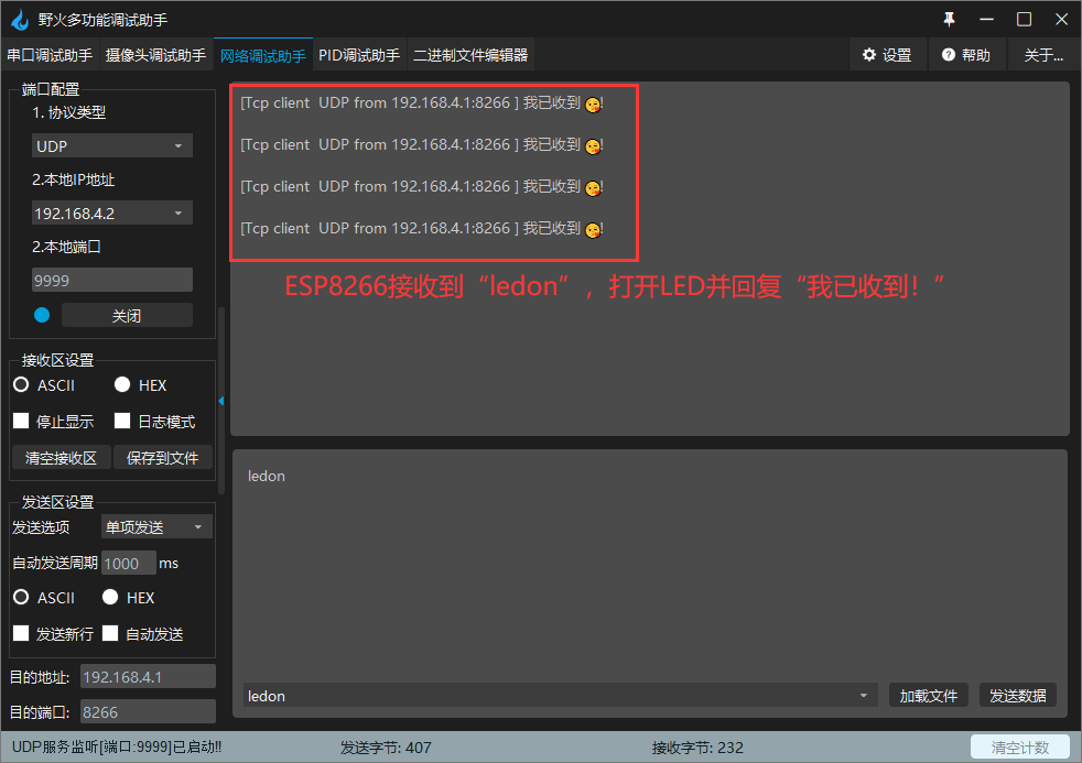
网络调试助手:

3.然后去验证是否可以通信。
4.验证:
注:源代码评论获取哟!!!![]()
![]()


 5519
5519


 被折叠的 条评论
为什么被折叠?
被折叠的 条评论
为什么被折叠?
 到【灌水乐园】发言


