


一、硬件电路:
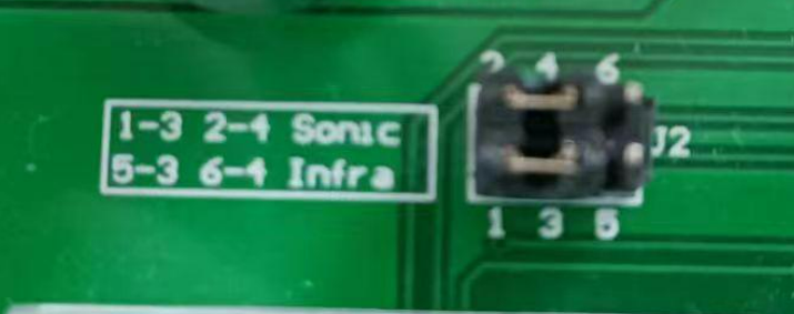
1、外接引脚:
通过切换跳帽,我们可以选择不同的发送接收端
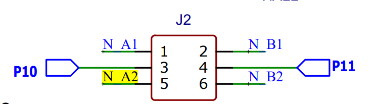
2、发送端:
(1)JS2连接着超声波探头,N-Al传入的信号通过硬件电路调制后,由JS2连接的超声波发送端发送超声波
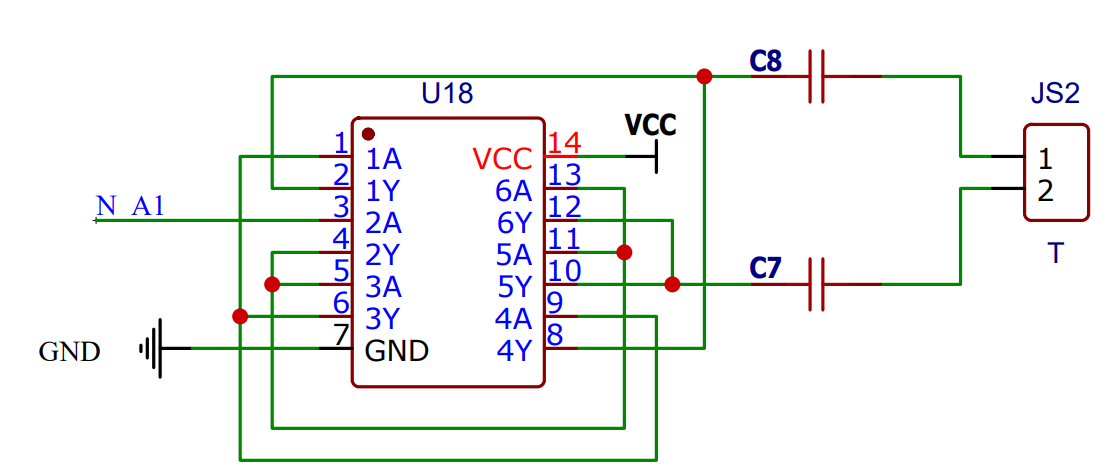
(2)

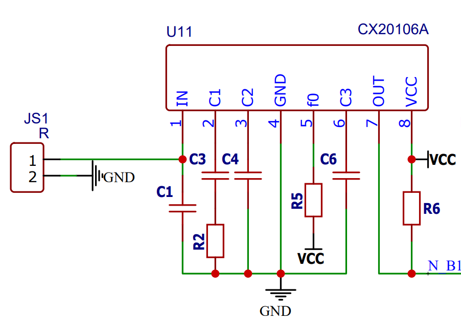
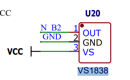
3、接收端:
(1)JS1:连接着超声波模块的接收端,将接收来的信号传入CX20106A中,进行增益放大,如果为40MHZ,则往N-B1输出低电平
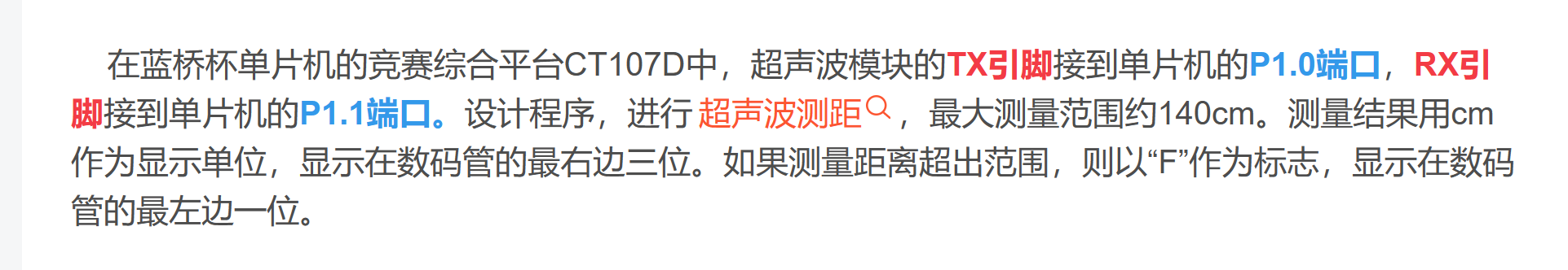
二、超声波模块测距思路:
1、往P10中传入八个40KHZ的信号(由单片机产生的最简单的就是方波信号,这里我们以占空比50%为例),然后通过超声波模块的发送端发送超声波信号
2、如果超声波信号碰到障碍物就会反弹回来,然后由超声波模块的接收端接收超声波信号,再由CX20106A将信号放大,并判断是否为40KHZ的信号,如果为40KHZ的信号就会输出低电平,即P11为低电平
3、我们可以通过定时器记录发送信号到成功接收的时间T,取20摄氏度时候的声速344M/S进行计算:
T = (TH0<<8) | TL0 * 10^(-6)s ,距离L = T * 344(M/S )/2= T *172(M/S )
三、超声波测距实验:
1、代码思路:
定时器1,数码管——》定时器0,超声波测距
2、参考代码:
#include <STC15F2K60S2.H>
#include <stdio.H>
#define u8 unsigned char
#define u16 unsigned int
sbit ult_tx = P1^0;
sbit ult_rx = P1^1;
code unsigned char Seg_Table[] =
{
0xc0, //0
0xf9, //1
0xa4, //2
0xb0, //3
0x99, //4
0x92, //5
0x82, //6
0xf8, //7
0x80, //8
0x90, //9
0x88, //A
0x83, //b
0xc6, //C
0xa1, //d
0x86, //E
0x8e //F
};

u16 ms_count;
//数码管
u8 COD[8],COT[9],PSI,seg_delay;
//超声波
u8 ult_sign;
void All_Close();
void Timer0_Init(void);
void SEG_Proc();
void Timer1_Init(void);
void main()
{
    All_Close();
    Timer0_Init();
    Timer1_Init();
    while(1)
    {
        SEG_Proc();
    }
}


/**************************************/
/*
    关闭无关设备
*/
void All_Close()
{
    //关闭蜂鸣器和继电器
    P0 = 0x00;
    P2 = P2 & 0x1f | (0x50<<1);
    P2 &= 0x1f;
    //关闭LED
    P0 = 0xff;
    P2 = P2 & 0x1f | (0x40<<1);
    P2 &= 0x1f;
}

/*****************数码管*******************/
void SEG_TSL(u8* input,u8* output)
{
    u8 i;
    for(i=0;i<8;i++)
    {
        switch(input[i])
        {
            case '0':output[i] = Seg_Table[0];break;
            case '1':output[i] = Seg_Table[1];break;
            case '2':output[i] = Seg_Table[2];break;
            case '3':output[i] = Seg_Table[3];break;
            case '4':output[i] = Seg_Table[4];break;
            case '5':output[i] = Seg_Table[5];break;
            case '6':output[i] = Seg_Table[6];break;
            case '7':output[i] = Seg_Table[7];break;
            case '8':output[i] = Seg_Table[8];break;
            case '9':output[i] = Seg_Table[9];break;
            case 'F':output[i] = Seg_Table[15];break;
        default:output[i] = 0xff;
        }
    }
}

void SEG_Show(u8 COD,u8 PSI)
{
    //消隐
    P0 = 0xff;
    P2 = P2 & 0x1f | (0x70<<1);
    P2 &= 0x1f;
    //位选
    P0 = 0x01<<PSI;
    P2 = P2 & 0x1f | (0x60<<1);
    P2 &= 0x1f;
    //段选
    P0 = COD;
    P2 = P2 & 0x1f | (0x70<<1);
    P2 &= 0x1f;
}
/*******************定时器***************************/
void Timer0_Isr(void) interrupt 1
{
  ms_count++;
    if(ms_count == seg_delay) seg_delay = 0;
    if(ms_count == 1000)ms_count = 0;

    SEG_Show(COD[PSI],PSI);
    if(PSI++ == 7)PSI = 0;
}

void Timer0_Init(void)        //1毫秒@12MHz
{
    AUXR &= 0x7F;            //定时器时钟12T模式
    TMOD &= 0xF0;            //设置定时器模式
    TL0 = 0x18;                //设置定时初始值
    TH0 = 0xFC;                //设置定时初始值
    TF0 = 0;                //清除TF0标志
    TR0 = 1;                //定时器0开始计时
    ET0 = 1;                //使能定时器0中断
    EA = 1;
}


void Timer1_Init(void)        //@12MHz
{
    AUXR &= 0xBF;            //定时器时钟12T模式
    TMOD &= 0x0F;            //设置定时器模式
//    TL1 = 0x18;                //设置定时初始值
//    TH1 = 0xFC;                //设置定时初始值
    TF1 = 0;                //清除TF1标志
//    TR1 = 1;                //定时器1开始计时
}
/******************超声波*************************/
u8 Ultrasonic()
{
    u8 ult_num=10;
    ult_tx = 0;
    //发送40kHZ 50%占空比信号
    TL1 = 0xF4;
    TH1 = 0xff;
    TR1 = 1;

    while(ult_num--)
    {
        while(TF1 == 0);
        TF1 = 0;
        ult_tx = !ult_tx;
    }
    TR1 = 0;
    //等待接收,并计时
    TL1 = 0;
    TH1 = 0;
    TR1 = 1;
    //接收到信号或计数超时
    while((ult_rx == 1) && (TF1 == 0));
    TR1 = 0;

    if(TF1 == 1)
    {
        TF1 = 0;
        ult_sign = 0;
        return 0xff;
    }
    else
    {
        ult_sign = 1;
        return ((TH1<<8)|TL1)*0.017;
    }

}
/*************************************************/
void SEG_Proc()
{
    u8 show_num;
    if(seg_delay) return;
    seg_delay = 1000;

    show_num = Ultrasonic();
    if(ult_sign == 1)
        sprintf(COT,"     %3u",(u16)show_num);
    else
        sprintf(COT,"F       ");
    SEG_TSL(COT,COD);
}


 3030
3030


 被折叠的 条评论
为什么被折叠?
被折叠的 条评论
为什么被折叠?
 到【灌水乐园】发言


