


💥💥💞💞欢迎来到本博客❤️❤️💥💥
🏆博主优势:🌞🌞🌞博客内容尽量做到思维缜密,逻辑清晰,为了方便读者。
⛳️座右铭:行百里者,半于九十。
📋📋📋本文目录如下:🎁🎁🎁
目录
💥1 概述
多旋翼无人机(UAV)由于其多功能性和机械简单性而在研究和商业应用中都获得了极大的普及。然而,尽管有这些优势,多旋翼系统在设计保证安全可靠飞行性能的强大控制架构方面仍然是一个相当大的挑战。按照今天的惯例,制导、控制和导航算法(GNC)的设计主要在仿真中进行。为了保证在仿真环境中生成的控制解决方案与真实飞行性能之间的无缝转换,仿真应以足够的保真度再现真实世界的行为。
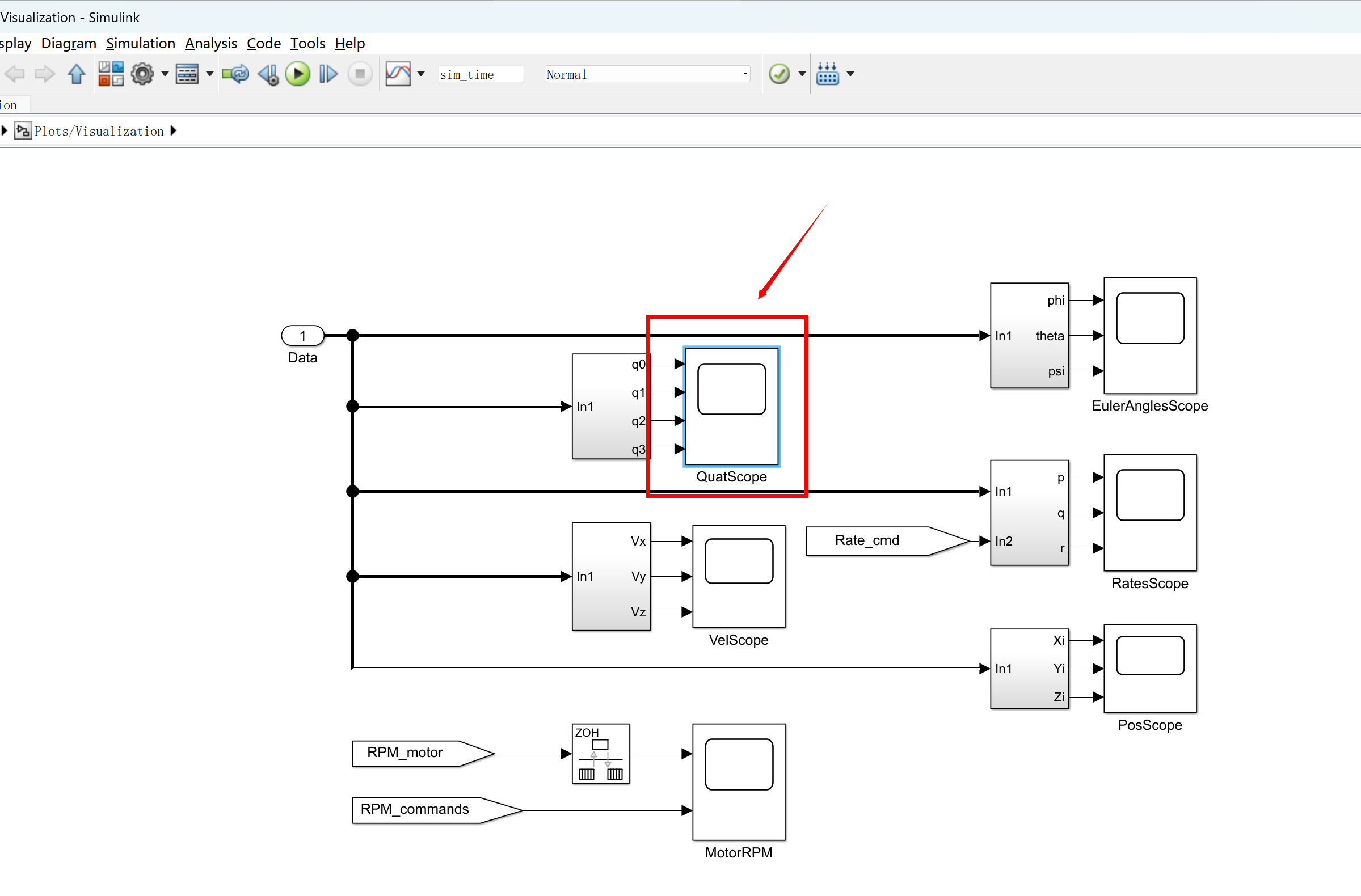
该仿真包括任意多旋翼无人机的改进动态模型。仿真非常模块化,允许用户指定几乎任何可以想象的多旋翼机身,无论对称性或特定布局如何。与在室外飞行真正的无人机相比,所包含的环境效果也有助于使模拟行为更自然。模拟包括随附论文文本中描述的所有场景。其中包括:任意非对称机身,改变机身质量或惯性矩或在飞行过程中引入执行器故障的能力,机身上的空气动力阻力,动态推力产生,不同的空气动力学螺旋桨模式,如涡环状态和叶片拍打效应。如果需要,用户可以关闭所有这些效果。
当前实现的控制器仅是内环角速率控制。由用户决定实施他们选择的更高级的控制方案。
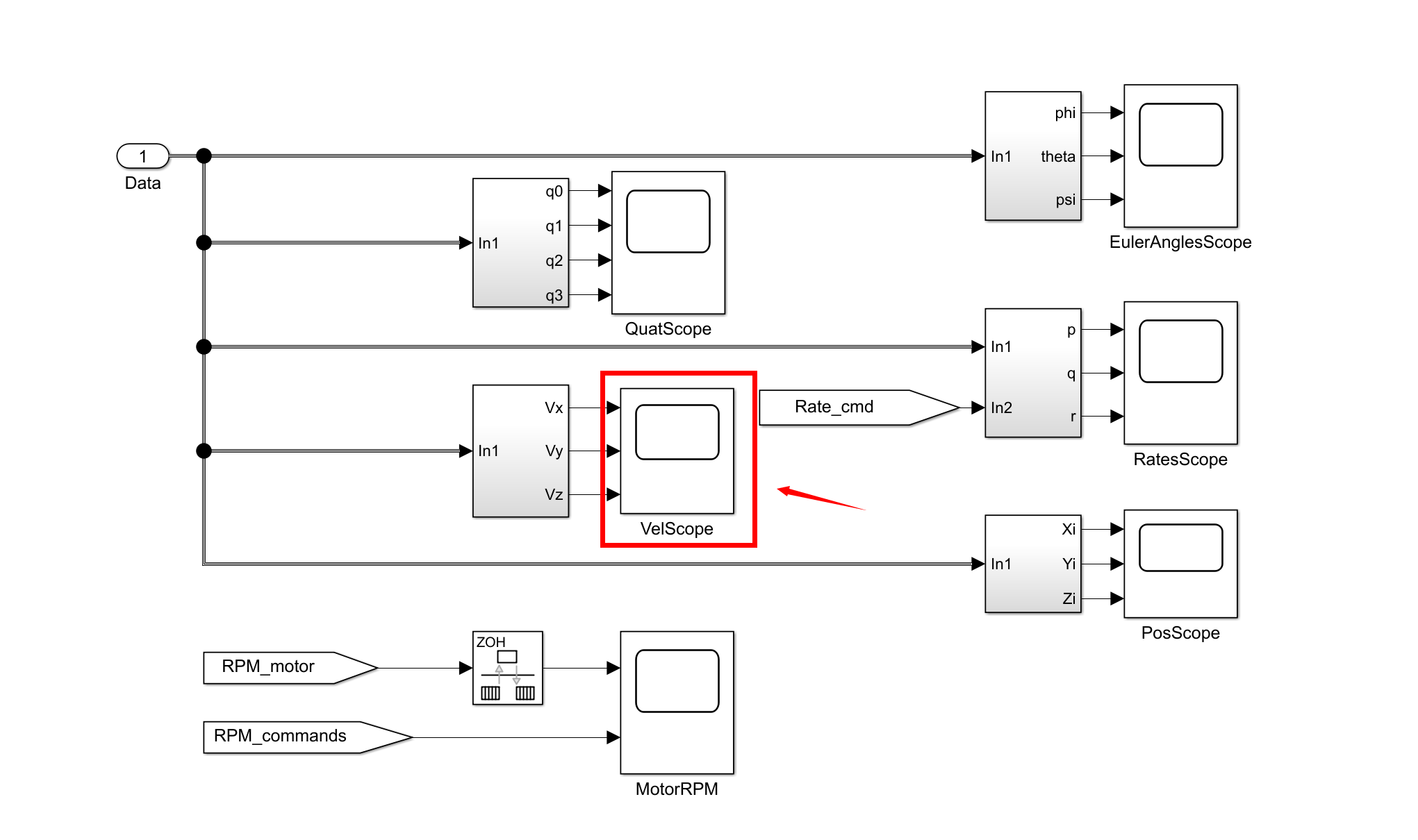
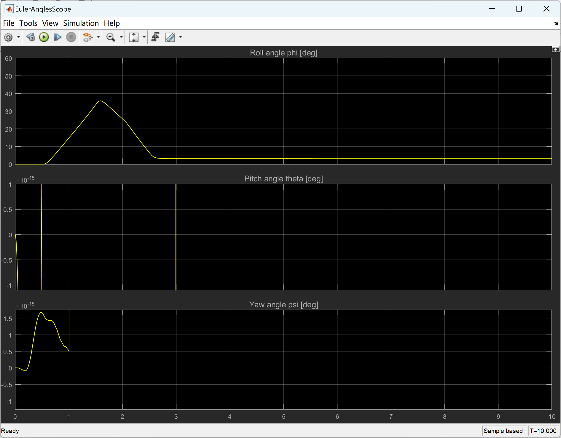
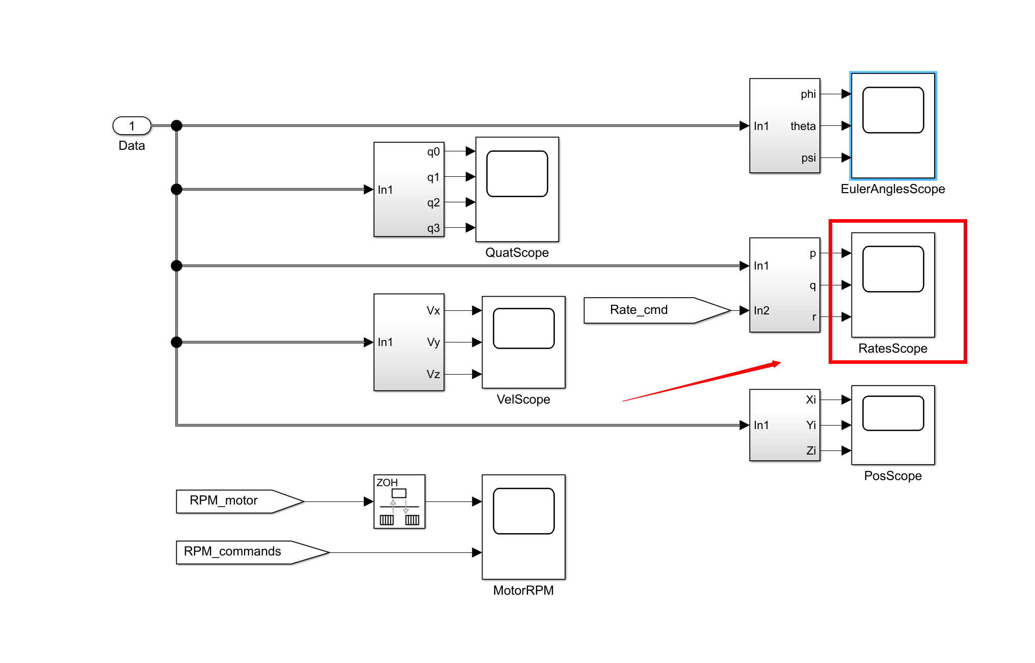
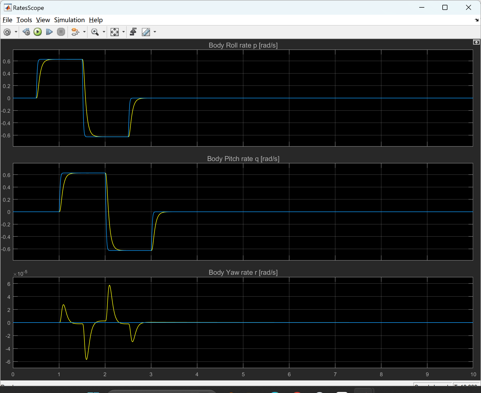
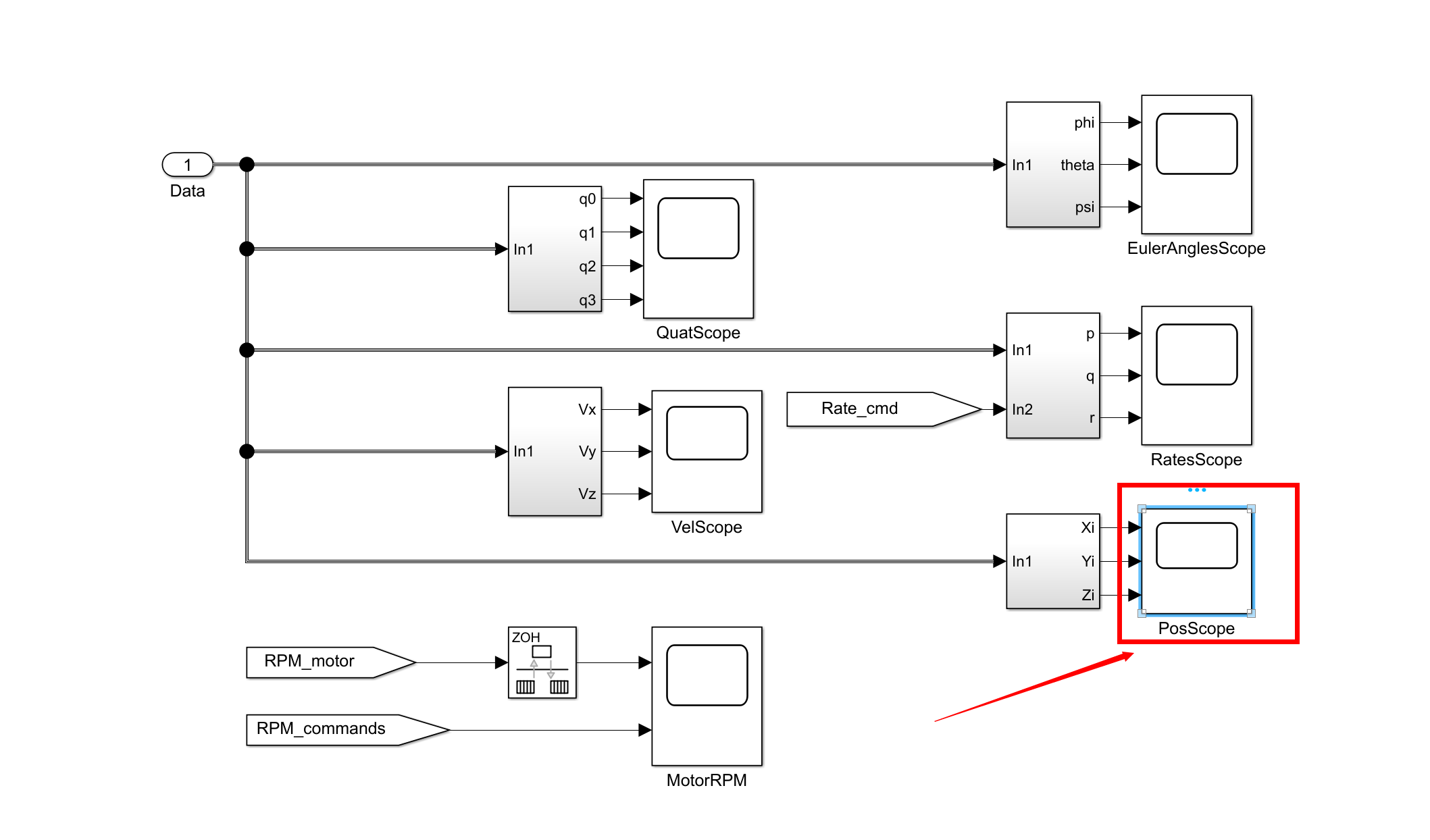
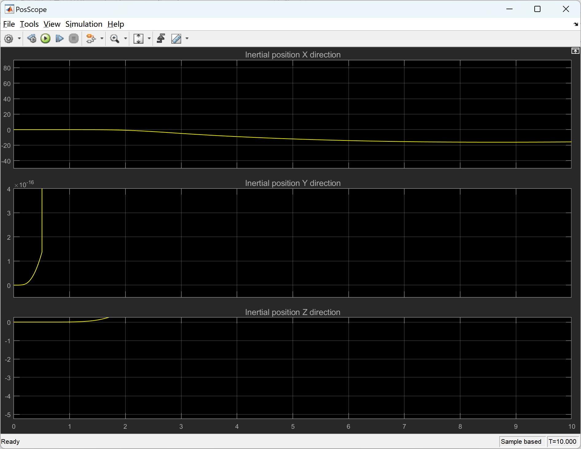
📚2 运行结果
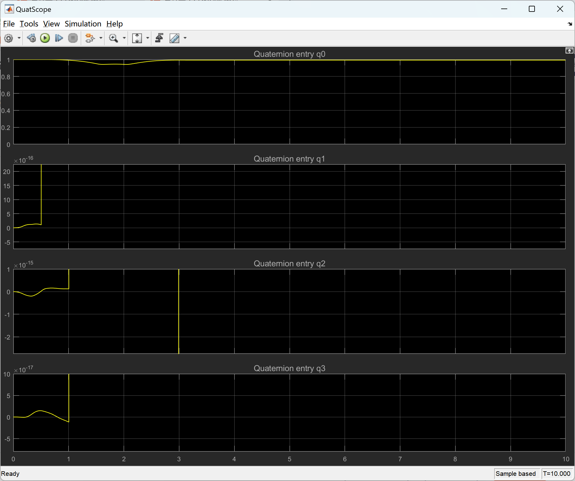
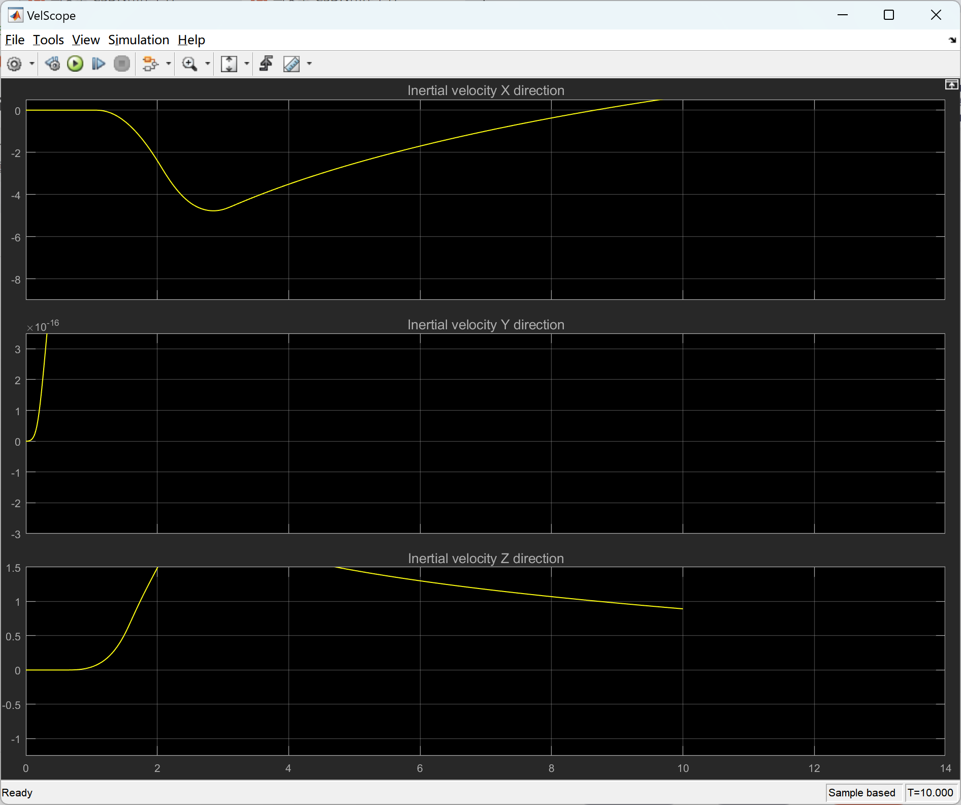
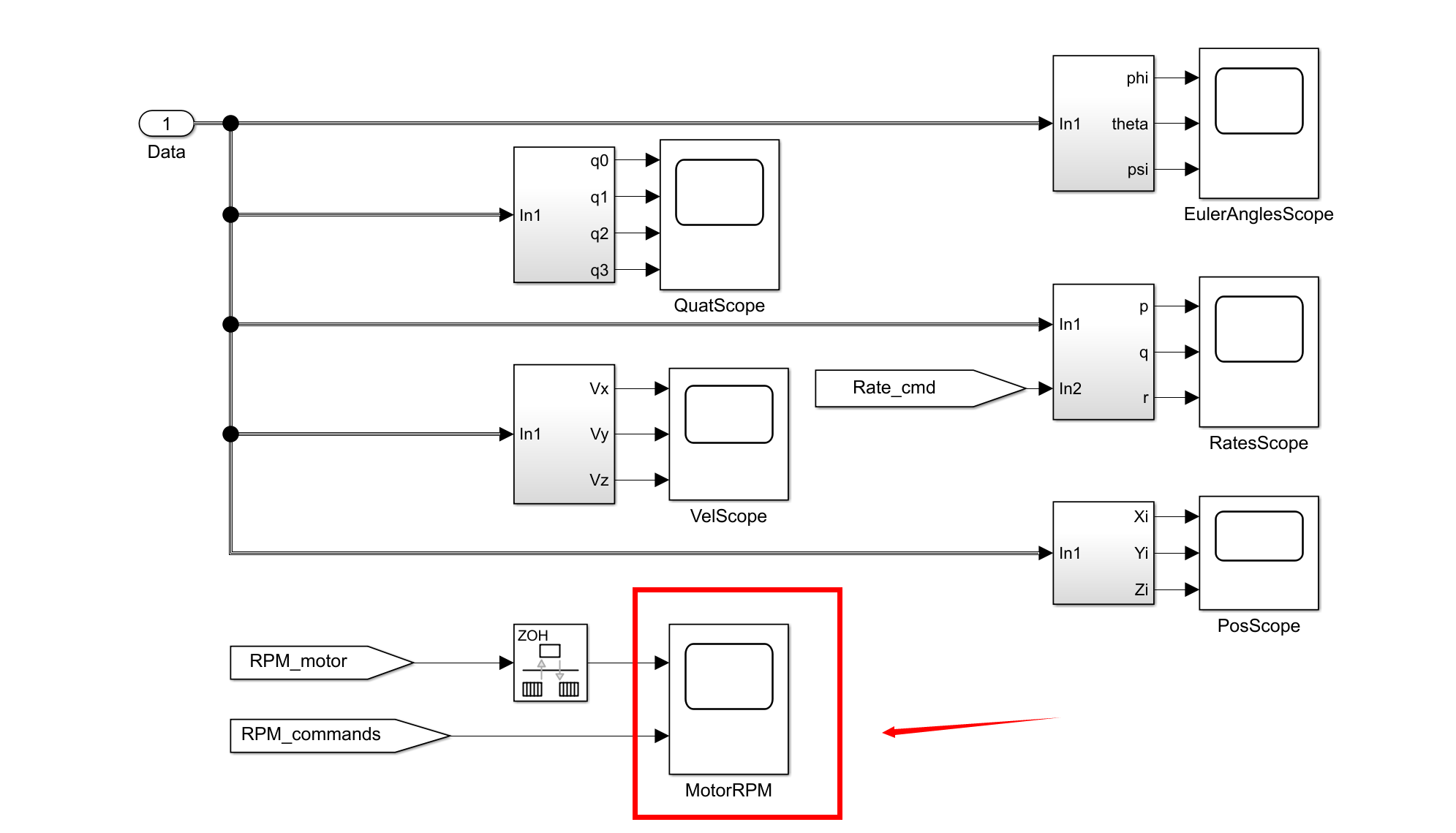
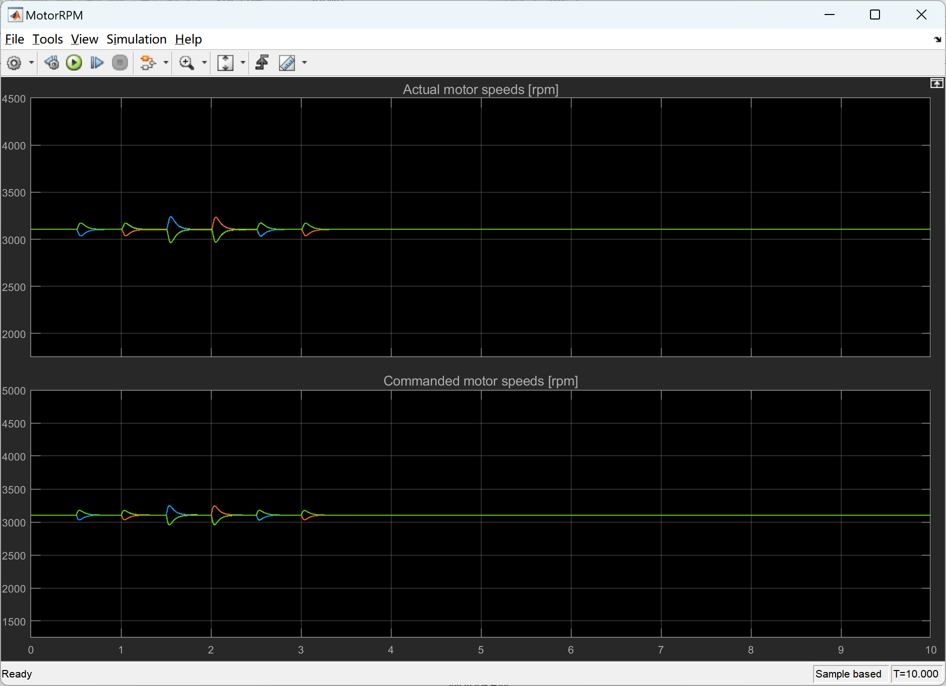
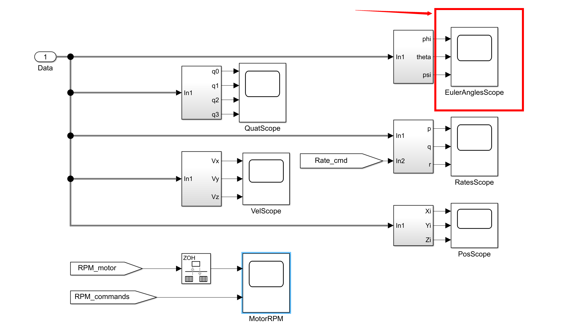
部分代码:
clear all;close all;clc
%--------------------------------------------------------------------------
t_control = 1/500; % Controller/state estimation frequency 500Hz [s]
t_sim = t_control/2; % Simulation frequency 1000Hz [s]
sim_time = 10.0; % Duration of simulation [sec]
r2d = 180/pi; % Conversion factor radians to degrees [deg/rad]
d2r = pi/180; % Conversion factor degrees to radians [rad/deg]
g = 9.80665; % Acceleration of gravity [m/s^2]
rpm2radpersec = 2*pi/60; % Conversion factor RPM to rad/sec [rad/(s*rpm)]
rho = 1.225; % Density of air [kg/m^3]
%--------------------------------------------------------------------------
%%%%%%%%%%%%%%%%%%%%%%%%%%%%%%%%%%%%%%%%%%%%%%%%%%%%%%%%%%%%%%%%%%%%%%%%%%%
% Quad specific configuration parameters %
%%%%%%%%%%%%%%%%%%%%%%%%%%%%%%%%%%%%%%%%%%%%%%%%%%%%%%%%%%%%%%%%%%%%%%%%%%%
% The coordinate system used in this model is defined as follows:
% X: pointing forward, Roll axis
% Y: pointing to the right, Pitch axis
% Z: pointing down, Yaw axis
% To define the geometry of the airframe, the following convention is used:
% - the base airframe is assumed to be somewhat symmetric
% - the CoG for the base airframe coincides with the geometric center in X/Y plane (but is shifted along Z axis)
% - the motor arm length in X/Y plane is defined as the distance to the geometric center of the base airframe
% - motor thrust is generated at the prop, which is offset a distance (along Z) from the geometric center
% - motor thrust vector may be misaligned from purely Z direction, so a set of rotation angles is given for each motor
% - real position of CoG is given as a position vector from geometric center
% - everything is expressed in body coordinate system described above
%%%%%%%%%%%%%%%%%%%%%%%%%%%%%%%%%%%%%%%%%%%%%%%%%%%%%%%%%%%%%%%%%%%%%%%%%%%
Noise_flag = 0; % Set to 1 for sensor/estimation noise, to 0 for no noise
Coriolis_correction = 1; % Set to 1 to cancel omega x (J*omega) term in control law, 0 if not
Dyn_thrust = 0; % Set to 1 to engage dynamic thrust effects, to 0 to disengage
Blade_flapping = 0; % Set to 1 to engage blade flapping effects, to 0 to disengage
%%%%%%%%%%%%%%%%%%%%%%%%%%%%%%%%
% Initial conditions
Att_init = [0;0;0] * d2r; % Initial airframe attitude in Euler angles Roll/Pitch/Yaw for 6DOF block [deg]
omega_init = [0;0;0]; % Initial angular rates in Body frame for 6DOF block [rad/s]
Vb_init = [0;0;0]; % Initial velocity in Body frame for 6DOF block [m/s]
Xi_init = [0;0;0]; % Initial position in Inertial frame for 6DOF block [m]
rpm_init = 3104.5025852; % Initial motor speed [rpm]
q_init = rpy2quat(Att_init); % Compute the initial attitude quaternion
R_IB_init = rpy2rot(Att_init); % Compute the initial rotation matrix R_IB
Vi_init = R_IB_init' * Vb_init; % Compute the initial velocity in Inertial axes
%%%%%%%%%%%%%%%%%%%%%%%%%%%%%%%%
% Parameters for aerodynamic drag computation
a = 0.060; % Surface area of airframe visible along the Body x axis [m^2]
b = 0.060; % Surface area of airframe visible along the Body y axis [m^2]
c = 0.060; % Surface area of airframe visible along the Body z axis [m^2]
C_D = 0.40; % Drag coefficient [dimensionless]
Surface_params = [a;b;c]; % Combine the surface area parameters
%%%%%%%%%%%%%%%%%%%%%%%%%%%%%%%%
% Parameters for dynamic thrust computation
v_h = 4.0; % Induced aerodynamic velocity at hover [m/s]
kappa = 1.00; % Value for induced power factor in hover (chosen to make transition from different states continuous)
k1 = -1.125; % Empirical values taken from Hoffmann_2011
k2 = -1.372; % Empirical values taken from Hoffmann_2011
k3 = -1.718; % Empirical values taken from Hoffmann_2011
k4 = -0.655; % Empirical values taken from Hoffmann_2011
%%%%%%%%%%%%%%%%%%%%%%%%%%%%%%%%
% Parameters for blade flapping computation
k_a1s = 1.5 / 4.0; % Gain in linear relationship between wind velocity and flapping angle [deg/(m/s)]
k_beta = 0.23; % Stiffness of the propeller blades [Nm/rad]
%%%%%%%%%%%%%%%%%%%%%%%%%%%%%%%%
% Real airframe data
CoG_real = [0;0;0.001]; % Location of center of gravity w.r.t. geometric center (in Body axes) [m]
mass_real = 0.550; % Complete airframe mass [kg]
Jxx = 0.003960; %
Jxy = 0; %
Jxz = 0; %
Jyx = 0; %
Jyy = 0.003845; % Moment of inertia for multirotor w.r.t center of gravity [kg*m^2]
Jyz = 0; %
Jzx = 0; %
Jzy = 0; %
Jzz = 0.007350; %
J_real = [Jxx Jxy Jxz;Jyx Jyy Jyz;Jzx Jzy Jzz]; % Moment of inertia matrix
%%%%%%%%%%%%%%%%%%%%%%%%%%%%%%%%
% MotorMatrix_real holds all the information about the actual performance
% of each actuator. The data is arranged as one row per motor/prop combo:
% 1 : Motor arm angle measured clockwise (looking from above) from the positive X axis (forward direction) [deg]
% 2 : Distance of prop/motor in X/Y plane from the geometric center of the airframe [m]
% 3 : Distance of prop/motor in Z direction from the geometric center of the airframe [m]
% 4 : Direction of prop rotation: -1 for CW, +1 for CCW [unitless]
% 5 : Control effectiveness of the actuator (nominally 1.0)
% 6 : First-order motor transfer function time constant [sec]
% 7..8 : Two coefficients that describe the RPM to thrust [N] transfer function for static conditions [a1 a2]
% Thrust = a1 * RPM + a2 * RPM^2
% 9..10 : Two coefficients that describe the RPM to torque [Nm] transfer function for static conditions [b1 b2]
% Torque = b1 * RPM + b2 * RPM^2
% 11 : Minimum RPM value of the actuator
% 12 : Maximum RPM value of the actuator
% 13..15 : Rotations of thrust vector around Body-fixed axes away from nominal direction [deg]
% Nominal direction of thrust vector is [0;0;-1]
% Rotation order from body to motor axes is Yaw/Pitch/Roll (Euler angle sequence (1,2,3))
% 16 : Propeller diameter [m]
% 17 : Propeller mass [kg]
MotorMatrix_real = [045 , 0.170 , -0.028 , -1 , 1.0 , 0.010 , [9.6820 , 0.010872]*1e-5 , [1.4504 , 0.0016312]*1e-6 , 0000 , 6000 , [0.0 , 0.0 , 0.0] , 8*2.54/100 , 11/1000; ...
135 , 0.170 , -0.028 , +1 , 1.0 , 0.010 , [9.6820 , 0.010872]*1e-5 , [1.4504 , 0.0016312]*1e-6 , 0000 , 6000 , [0.0 , 0.0 , 0.0] , 8*2.54/100 , 11/1000; ...
225 , 0.170 , -0.028 , -1 , 1.0 , 0.010 , [9.6820 , 0.010872]*1e-5 , [1.4504 , 0.0016312]*1e-6 , 0000 , 6000 , [0.0 , 0.0 , 0.0] , 8*2.54/100 , 11/1000; ...
315 , 0.170 , -0.028 , +1 , 1.0 , 0.010 , [9.6820 , 0.010872]*1e-5 , [1.4504 , 0.0016312]*1e-6 , 0000 , 6000 , [0.0 , 0.0 , 0.0] , 8*2.54/100 , 11/1000];
%%%%%%%%%%%%%%%%%%%%%%%%%%%%%%%%
% Nominal airframe data (without disturbance/uncertainties)
CoG_nominal = [0;0;0.001]; % Location of center of gravity w.r.t. geometric center (in Body axes) [m]
mass_nominal = 0.550; % Complete airframe mass [kg]
Jxx = 0.003960; %
🎉3 参考文献
文章中一些内容引自网络,会注明出处或引用为参考文献,难免有未尽之处,如有不妥,请随时联系删除。
[1] Vervoorst J W .A modular simulation environment for the improved dynamic simulation of multirotor unmanned aerial vehicles[J]. 2016.


 233
233


 被折叠的 条评论
为什么被折叠?
被折叠的 条评论
为什么被折叠?
 到【灌水乐园】发言


