


目录
二、创造自己的驱动目录以及创造驱动文件,编写Makefile文件
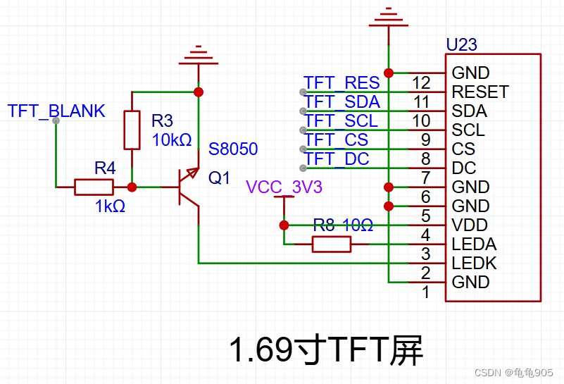
此文用于记录泰山派驱动st7789芯片的tft lcd 屏幕
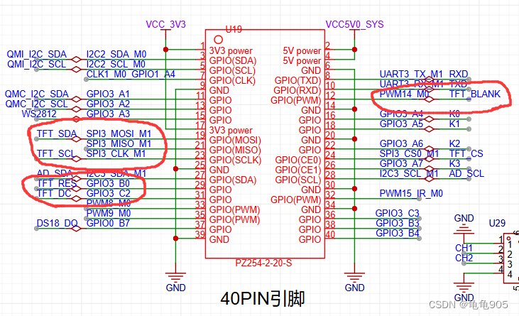
硬件连接:
参考文档:
8. SPI子系统–oled屏实验 — [野火]嵌入式Linux驱动开发实战指南——基于LubanCat-RK系列板卡 文档 (embedfire.com)
NanoPi NEO Air使用十一:编写SPI驱动点亮TFT屏幕,ST7789V_nanopi led-CSDN博客
过程:
一、修改设备树,添加子节点
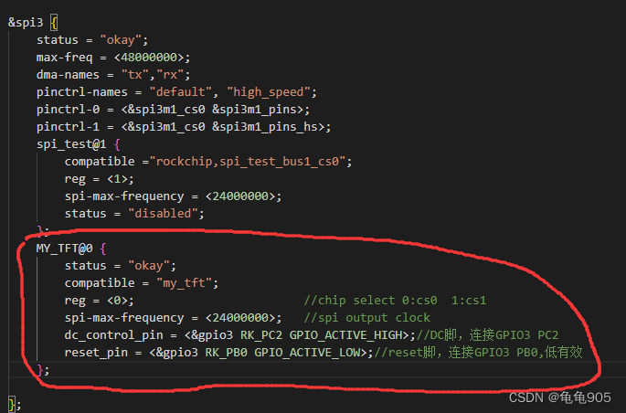
在spi3节点中添加自己定义的MY_TFT节点,并添加dc,reset两个引脚属性
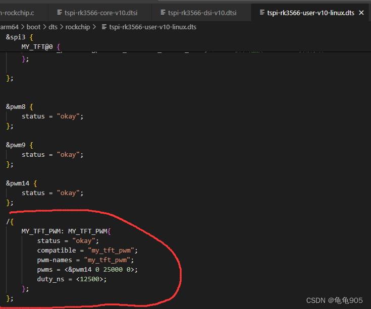
在设备树中添加自己的MY_TFT_PWM节点,设置输出通道0,周期25000,极性0,占空比12500(50%)这里配置的pwm参数后面在驱动中还会修改,这里主要就是申请一个pwm14设备
二、创造自己的驱动目录以及创造驱动文件,编写Makefile文件
我们进入到sdk里的kernel/drivers目录中,新建一个文件夹my_drivers用于存储自制驱动
然后在这个文件夹里再新建一个my_tft文件夹,用于保存st7798屏幕驱动的源文件,在每个目录下都要修改或者新建Makefile以确保sdk可以编译我们的驱动
本次实验创建的目录树图:
sdk > kernel > drivers > --my_drivers > --my_tft > --my_tft.c
--Makefile --Makefile --my_tft_pwm.c
--Makefile
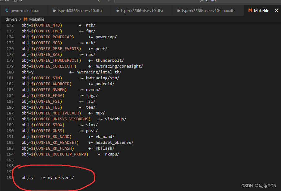
其中dirvers目录下的Makefile是自带的,我们只需要在里面添加my_tft文件夹就行
然后在my_drivers文件夹中的Makefile也简单地写一句添加my_tft文件夹即可
obj-y += my_tft/在my_tft文件夹中创造了两个.c文件用于编写驱动,还有一个Makefile用于指定编译,内容为
obj-y				  += my_tft.o
obj-y				  += my_tft_pwm.o
三、编写驱动文件
博主是刚入坑学习的新手,自学的时候都是基本按照网上找的教程,具体为什么要这样目前还没有很明白,有问题希望指出
先来写比较简单的pwm驱动文件
my_tft_pwm.c
//具体要使用什么库没有深入分析,只是一股脑把库都贴上来了
#include <linux/pwm.h>
#include <linux/device.h>
#include <linux/errno.h>
#include <linux/err.h>
#include <linux/gpio/consumer.h>
#include <linux/hrtimer.h>
#include <linux/ktime.h>
#include <linux/kernel.h>
#include <linux/module.h>
#include <linux/mod_devicetable.h>
#include <linux/of.h>
#include <linux/of_gpio.h>
#include <linux/platform_device.h>
#include <linux/property.h>

struct pwm_device	*my_tft_pwm;

static int my_tft_pwm_probe(struct platform_device *pdev)
{
	int ret = 0;
	struct device_node *nd = pdev->dev.of_node; // 保存节点
	printk("match success \n");

	if (nd){
		my_tft_pwm = devm_of_pwm_get(&pdev->dev, nd, NULL);
		if (IS_ERR(my_tft_pwm)) {
			printk(KERN_ERR" pwm_demo,get pwm error!!\n");
			return -1;
		}
	}
	else{
		printk(KERN_ERR" pwm_demoof_get_nd error!!\n");
		return -1;
	}
	/*配置频率10KHz 占空比50%*/
	pwm_config(my_tft_pwm, 25000, 50000);
	/*正常模式(正相)*/
	pwm_set_polarity(my_tft_pwm, PWM_POLARITY_NORMAL);
	pwm_enable(my_tft_pwm);

	return ret;
}

static int my_tft_pwm_remove(struct platform_device *pdev)
{
	pwm_config(my_tft_pwm, 0, 5000);
    pwm_free(my_tft_pwm);
	return 0;
}

/* 设备树匹配列表 */
static const struct of_device_id my_tft_pwm_of_match[] = {
	{ .compatible = "my_tft_pwm" },
	{ /* Sentinel */ }
};

//pwm驱动结构体
static struct platform_driver my_tft_pwm_driver = {
	.probe = my_tft_pwm_probe,
	.remove = my_tft_pwm_remove,
	.driver = {
		.name = "my_tft_pwm",
		.of_match_table = of_match_ptr(my_tft_pwm_of_match),
	},
};


module_platform_driver(my_tft_pwm_driver);
MODULE_LICENSE("GPL");
MODULE_AUTHOR("greentor");
最主要的是写probe函数,用于连接驱动和设备树,并初始化我们的pwm,设置周期,占空比等等
以及remove函数,用于退出设备时清除设备,释放内存
其他的基本都是固定格式
然后写st7789芯片驱动文件,比较复杂,但是如果有移植过单片机tft屏幕的经验的话看懂并不难
my_tft.c
#include <linux/spinlock.h>
#include <linux/spi/spi.h>
#include <linux/platform_device.h>
#include <linux/bitops.h>
#include <linux/init.h>
#include <linux/types.h>
#include <linux/kernel.h>
#include <linux/delay.h>
#include <linux/ide.h>
#include <linux/module.h>
#include <linux/errno.h>
#include <linux/gpio.h>
#include <linux/cdev.h>
#include <linux/device.h>
#include <linux/semaphore.h>
#include <linux/timer.h>
#include <linux/i2c.h>
#include <linux/of.h>
#include <linux/of_address.h>
#include <linux/of_gpio.h>


//自己修改参数
#define LCD_W 240
#define LCD_H 320

#define WHITE         	 0xFFFF
#define BLACK         	 0x0000
#define BLUE         	 0x001F
#define BRED             0XF81F
#define GRED 			 0XFFE0
#define GBLUE			 0X07FF
#define RED           	 0xF800
#define MAGENTA       	 0xF81F
#define GREEN         	 0x07E0
#define CYAN          	 0x7FFF
#define YELLOW        	 0xFFE0
#define BROWN 			 0XBC40
#define BRRED 			 0XFC07
#define GRAY  			 0X8430

struct my_tft_dev {
	dev_t devid;				/* 设备号 */
	struct cdev cdev;			/* cdev */
	struct class *class;		/* 类 */
	struct device *device;		/* 设备 */
	struct device_node	*nd; 	/* 设备节点 */
	int major;					/* 主设备号 */
	void *private_data;			/* 私有数据 */
	int dc_gpio;				/* 片选所使用的GPIO编号 */
    int res_gpio;               /* ips屏幕复位引脚 */
};

static struct my_tft_dev my_tftdev;

void my_tft_reginit(struct my_tft_dev *dev);

//1.69寸屏幕
struct spi_lcd_cmd {
    u8  reg_addr;  // command
    u8  len;       //需要从spi_lcd_datas数组里发出数据字节数
    int delay_ms;  //此命令发送数据完成后,需延时多久
};

//初始化时要发的命令,{命令,数据数量,延时}
struct spi_lcd_cmd cmds[] = {
    {0x36, 1, 30},
    {0x3A, 1, 30},
    {0xB2, 5, 30},
    {0xB7, 1
最低0.47元/天 解锁文章


 2623
2623

 被折叠的 条评论
为什么被折叠?
被折叠的 条评论
为什么被折叠?
 到【灌水乐园】发言


