


前言
最近为了准备智能车比赛,参加相关培训,受学长推荐受用VOFA+上位机可视化波形,协助电机转速PID调整。
但是我这个芯片吧,STC16它不支持在线仿真,所以看关键变量的话就必须得借助串口来协助调试程序了。
VOFA+简介
VOFA+是一个串口调试助手,但凭它简单的通信协议、数据可视化以及频域分析,三维打印等优点在众多串口调试助手中脱颖而出。
就凭一个打印波形,屁颠屁颠就冲这软件来了。
必要工作
下面讲解一下如何使用keil对STC16进行开发时,将需要重点关注的变量打印到VOFA+上来,甚至对其可视化。
配置STC16的UART模块
VOFA+本质上是一个串口,打印我们想要关注的数据就是需要STC16和串口之间的通信。STC16上有专门用于通信的模块UART(通用异步收发传输器),他的通信协议相较于其他的IIC,SPI,CAN等通信协议都简单得多,UART也更容易上手。
(UART 原理我就不讲了 直接贴代码吧)
uart.c文件
文件中包含uart初始化函数以及通信字符传输函数,文件中已经对printf做了重定向,像c语言直接printf(“”)想要的数据就可以实现了
#include "stc16f.h"
#include "stdio.h"
#include "uart.h"
#include "led.h"
#include "pid.h"

unsigned char  TX1_Cnt;    //发送计数
unsigned char  RX1_Cnt;    //接收计数
unsigned char  TX2_Cnt;    //发送计数
unsigned char  RX2_Cnt;    //接收计数
unsigned char  TX3_Cnt;    //发送计数
unsigned char  RX3_Cnt;    //接收计数
unsigned char  TX4_Cnt;    //发送计数
unsigned char  RX4_Cnt;    //接收计数

static uint8_t tempData[16] = {0,0,0,0,0,0,0,0,0,0,0x80,0x7F};


bit B_TX1_Busy; //发送忙标志
bit B_TX2_Busy; //发送忙标志
bit B_TX3_Busy; //发送忙标志
bit B_TX4_Busy; //发送忙标志

unsigned char  xdata RX1_Buffer[UART1_BUF_LENGTH]; //接收缓冲
unsigned char  xdata RX2_Buffer[UART2_BUF_LENGTH]; //接收缓冲

void Init_UART1(void)
{
	TR1 = 0;
	AUXR &= ~0x01;      //S1 BRT Use Timer1
	AUXR |=  (1<<6);    //Timer1 set as 1T mode
	TMOD &= ~(1<<6);    //Timer1 set As Timer
	TMOD &= ~0x30;      //Timer1_16bitAutoReload;
	TH1 = (unsigned char)(BaudRate1Timer / 256);
	TL1 = (unsigned char)(BaudRate1Timer % 256);
	ET1 = 0;    //禁止中断
	INTCLKO &= ~0x02;  //不输出时钟
	TR1  = 1;

	SCON = (SCON & 0x3f) | 0x40;    //UART1模式, 0x00: 同步移位输出, 0x40: 8位数据,可变波特率, 0x80: 9位数据,固定波特率, 0xc0: 9位数据,可变波特率
//  PS  = 1;    //高优先级中断
    ES  = 1;    //允许中断
    REN = 1;    //允许接收
    P_SW1 &= 0x3f;
//  P_SW1 |= 0x00;      //UART1 switch to, 0x00: P3.0 P3.1, 0x40: P3.6 P3.7, 0x80: P1.6 P1.7, 0xC0: P4.3 P4.4
//  PCON |=  (1<<4);   //内部短路RXD与TXD, 做中继, ENABLE,DISABLE

    B_TX1_Busy = 0;
    TX1_Cnt = 0;
    RX1_Cnt = 0;
}
void PrintString1(unsigned char *puts)
{
    for (; *puts != 0;  puts++)     //遇到停止符0结束
    {
        SBUF = *puts;
        B_TX1_Busy = 1;
        while(B_TX1_Busy);
    }
}
void UART1_int (void) interrupt 4
{
	LED_A_TG;
    if(RI)
    {
        RI = 0;
        RX1_Buffer[RX1_Cnt] = SBUF;
        if(++RX1_Cnt >= UART1_BUF_LENGTH)   RX1_Cnt = 0;
    }

    if(TI)
    {
        TI = 0;
        B_TX1_Busy = 0;
    }
}
void UART1_SendData(char dat)
{
//	ES = 0;			//关串口中断
	SBUF = dat;
	B_TX1_Busy = 1;
	while(B_TX1_Busy); //等待发送成功
//	TI = 0;			//清除发送中断标志
//	ES = 1;			//开串口中断
}
void UART1_SendString(char *s)
{
	while(*s)//检测字符串结束符
	{
		UART1_SendData(*s++);//发送当前字符
	}
}
//void Vofa_Graph()
//{
//	static float temp[2];
//
//	temp[0] = pid_Speed.ReferenceValue;
//	temp[1] = pid_Speed.ActualValue;
	memcpy(tempData, (uint8_t *)&temp, sizeof(temp));
//	write((char*)temp,sizeof(float)*2);

//}

char putchar(char c)
{
	UART1_SendData(c);
	return c;
}
uart.h文件
#ifndef _UART_H_
#define _UART_H_

#include "stc16f.h"

#define BaudRate1   9600//
#define BaudRate2   19200
#define BaudRate3   115200
#define BaudRate4   4800

#define BaudRate1Timer   (65536 - MAIN_Fosc / BaudRate1 / 4)
#define BaudRate2Timer   (65536 - MAIN_Fosc / BaudRate2 / 4)
#define BaudRate3Timer   (65536 - MAIN_Fosc / BaudRate3 / 4)
#define BaudRate4Timer   (65536 - MAIN_Fosc / BaudRate4 / 4)

#define UART1_BUF_LENGTH    128
#define UART2_BUF_LENGTH    128
#define UART3_BUF_LENGTH    128
#define UART4_BUF_LENGTH    128

void Init_UART1(void);
void Init_UART2(void);
void Init_UART3(void);
void Init_UART4(void);
void PrintString1(u8 *puts);
void UART1_SendData(char dat);
void UART1_SendString(char *s);
void Vofa_Graph(void);

#endif
我这里使用Timer1作为UART1的波特率发生器。虽然STC16有很多UART,用一个就够了,而且Timer3Timer4用来捕获电机的编码器输入进行测速,Timer0做定时中断。
若需要修改波特率,需要在uart.h文件中修改BaudRate1宏定义即可。
VOFA+使用
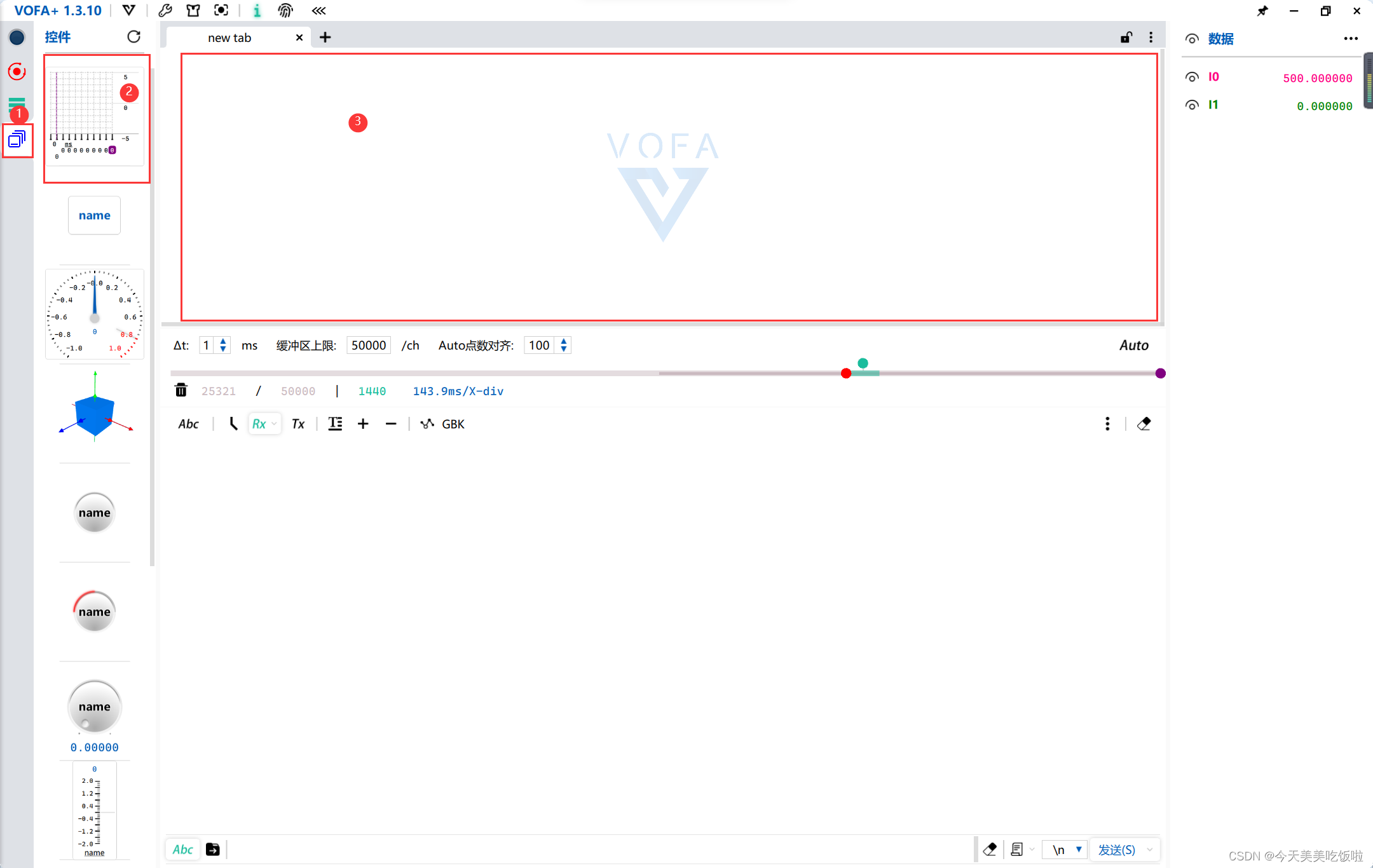
打开VOFA软件后,对VOFA进行配置

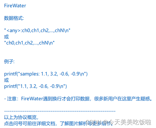
数据引擎选择firewater协议,这个协议可以简单打印数据波形。
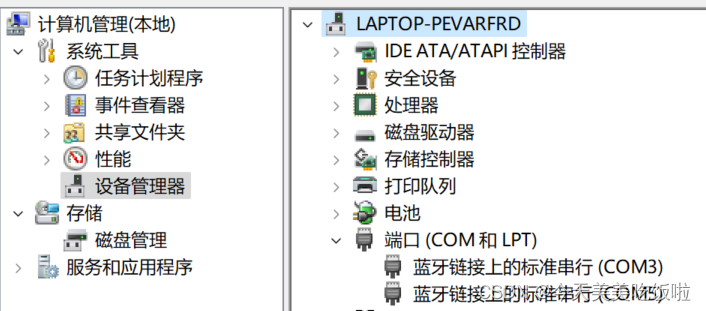
数据接口选择stc16的com端口号,这个可以进设备管理器查看
根据你配置的UART1的波特率,在VOFA上选择相同的波特率波特率一定要跟配置的一样,不然打印出来的就是乱码。
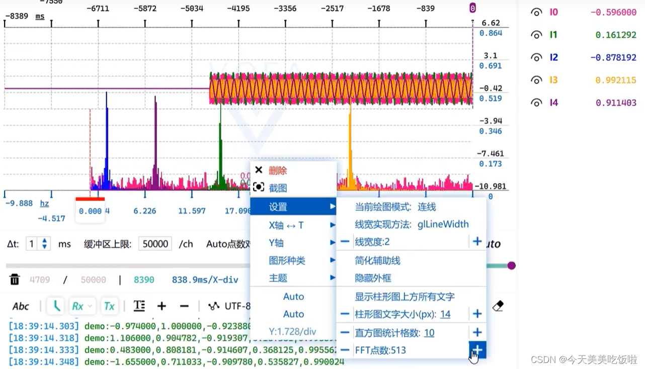
根据firewater的协议,打印你想要观察的数据
打印数据,printf函数我放在我的主函数里面的,整个文件贴上来了
#include <stdio.h>
#include <stdlib.h>
#include <string.h>
#include "STC16f.h"
#include "intrins.h"
#include "clk.h"
#include "led.h"
#include "timer.h"
#include "wake.h"
#include "pwm.h"
#include "uart.h"
#include "encoder.h"
#include "pid.h"
#include "math.h"
int main()
{
WTST = 0;
EA = 1; // enable global Interrupt
P0M1 = 0x00; P0M0 = 0x00; //设置为准双向口
P1M1 = 0x00; P1M0 = 0x00; //设置为准双向口
P2M1 = 0x00; P2M0 = 0x00; //设置为准双向口
P3M1 = 0x00; P3M0 = 0x00; //设置为准双向口
P4M1 = 0x00; P4M0 = 0x00; //设置为准双向口
P5M1 = 0x00; P5M0 = 0x00; //设置为准双向口
P6M1 = 0x00; P6M0 = 0x00; //设置为准双向口
P7M1 = 0x00; P7M0 = 0x00; //设置为准双向口
Init_Clock(IRC24M);
Init_UART1();
Init_PID();
Init_PWMA();
Forward();
Init_Encoder();
Init_Timer0();
LED_A_Off;
LED_B_Off;
// RSTCFG |= 1<<4; // 使P5.4管脚作复位脚
while(1)
{
static int t=0;
t++;
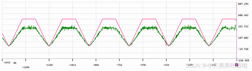
printf("%0.2f,%0.2f \r\n",pid_Speed.ReferenceValue,pid_Speed.ActualValue);
}
}
注意printf()函数的写法必须跟协议的一样,数据中间不能再有其他的字符,不然只会打印数据,没有波形。
在vofa中选择控件,拖动坐标轴到旁边的tab框框里。
右键坐标轴填充
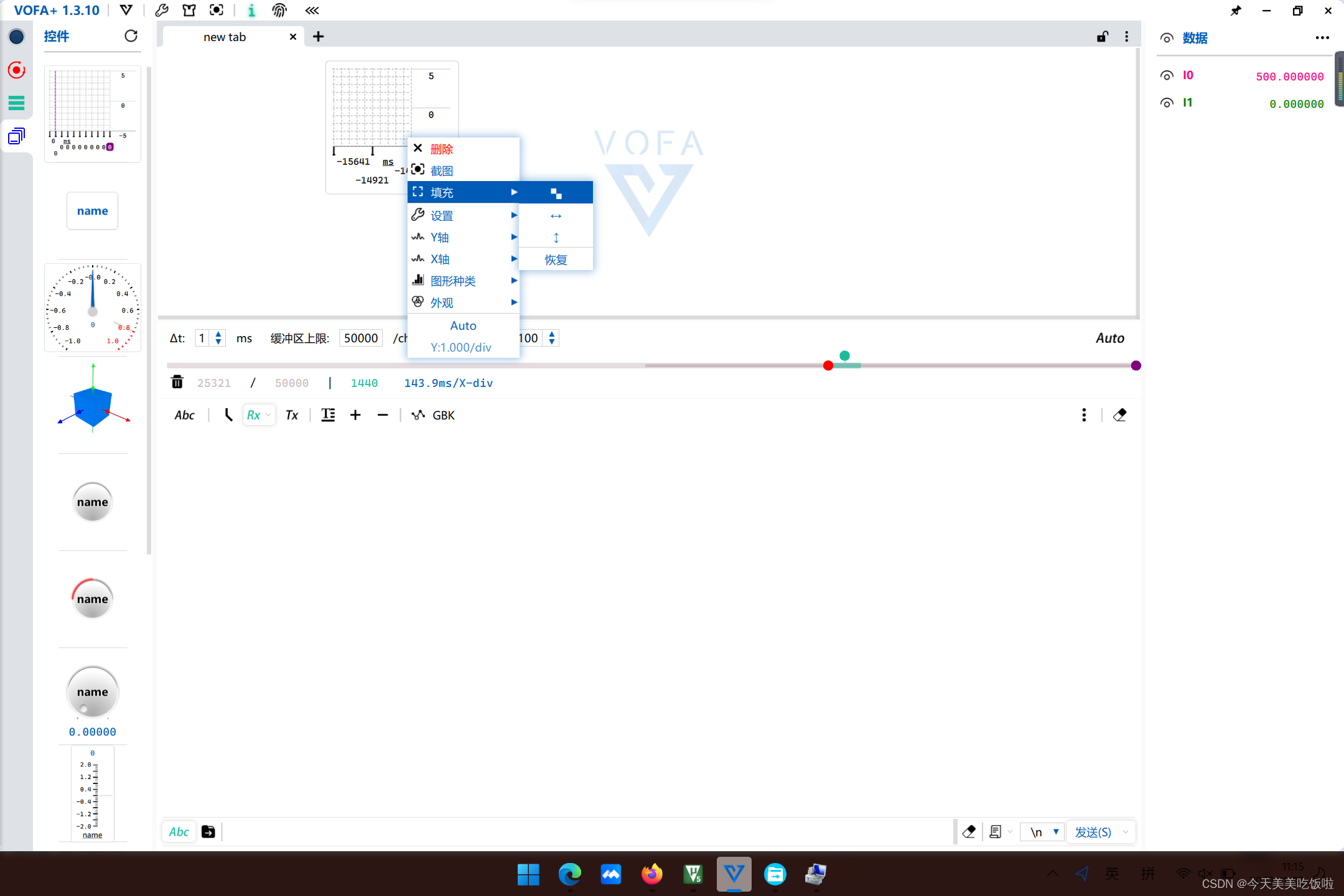
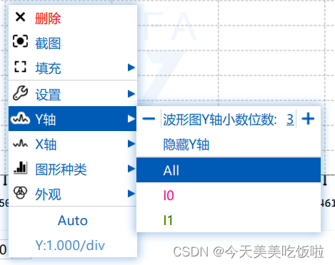
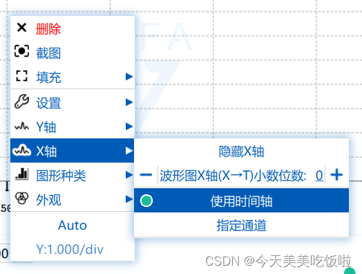
X轴选择时间轴,Y轴选择ALL
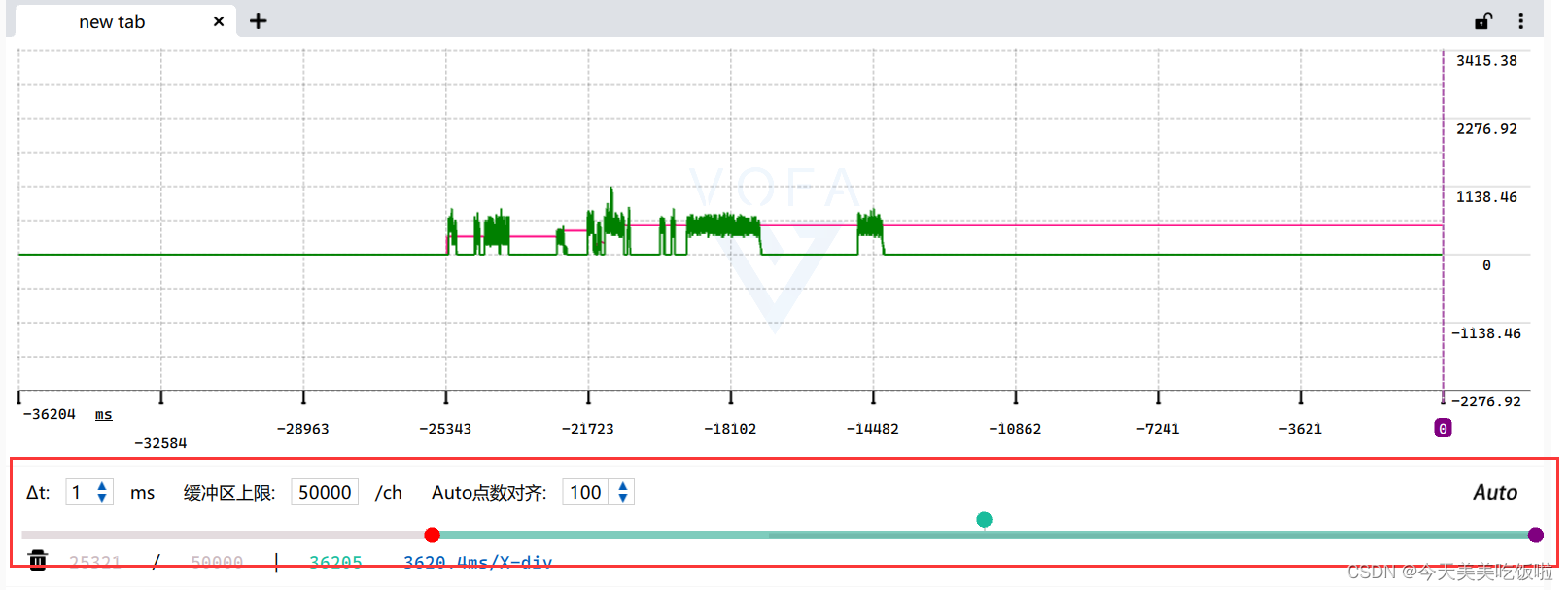
拖动下边的红色端子,就可以调节波形的刻度了
2022-12-07更新
最近准备智能车比赛已经换STC32芯片学习了,但最近也没有写博客。资源已上传到gitee开源
https://gitee.com/XuHaotianGaoHuizhen/STC32


 1万+
1万+

 被折叠的 条评论
为什么被折叠?
被折叠的 条评论
为什么被折叠?
 到【灌水乐园】发言


