


使用通用输入输出接口(GPIO)实现PC6管脚输出状态翻转
使用的keil
其主函数为:
#include "STM32F10X.h"
void GPIO_Config(void);
int main(){
	int i;
	GPIO_Config(); //配置Pc6管脚为推挽输出
	while(1){
		GPIO_SetBits(GPIOC,GPIO_Pin_6); //GPIOC6输出高电平
		for(i=0;i<500000;i++){}	//延时
		GPIO_ResetBits(GPIOC,GPIO_Pin_6);//GPIOC6输出低电平
		for(i=0;i<500000;i++){}  //延时
	}
}
void GPIO_Config(){
	//定义一个GPIO_InitTypeDef类型的结构体,该结构体原型在stm32f10x_gpio.h中
	GPIO_InitTypeDef GPIO_InitStructure;
	//使能GPIOC时钟,相当于给GPIOC供电,使能时钟是所有外设工作前的第一步。
	RCC_APB2PeriphClockCmd(RCC_APB2Periph_GPIOC,ENABLE);
	GPIO_InitStructure.GPIO_Pin=GPIO_Pin_6;	//选择管脚
	GPIO_InitStructure.GPIO_Speed=GPIO_Speed_50MHz;	//GPIO速度
	//GPIO工作模式-推挽输出
	GPIO_InitStructure.GPIO_Mode=GPIO_Mode_Out_PP;
	 //按照结构体GPIO_InitStructure的配置进行初始化,选择端口为GPIOC
	GPIO_Init(GPIOC,&GPIO_InitStructure);
}
运行成功后,将生成的.hex文件导入芯片中,
我使用的是Proteus 8 Professional仿真软件。
其线路图如下:
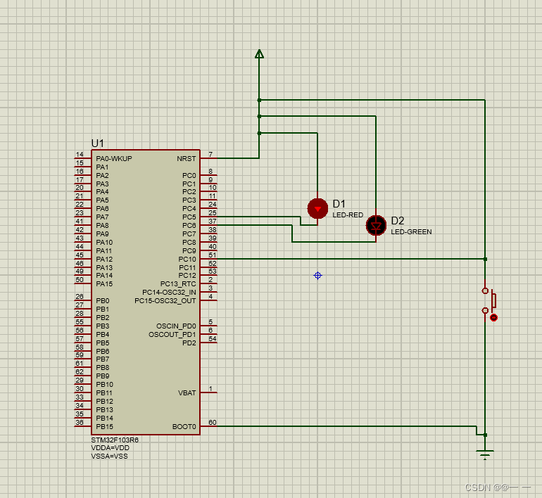
运行,点击开关后,两灯会一亮一灭。
因为是新手,线路图画的有些乱,继续学习。


 283
283


 被折叠的 条评论
为什么被折叠?
被折叠的 条评论
为什么被折叠?
 到【灌水乐园】发言


