


照旧,声明该篇文章是我摘录了别人的一部分合起来的,会对每一个引文先声明,仅供学习
Linux系统SPI驱动总结(一)--------部分内容引用自https://blog.csdn.net/xiezhi123456/article/details/80097780
一、SPI简介
SPI是“Serial Peripheral Interface”的缩写,串行外设接口,是一种四线制的同步串行通信接口,用来连接MCU、传感器、存储设备,SPI设备分为主设备和从设备两种,用于通信和控制的四根线分别是:CS(片选信号)、SCLK(时钟信号)、MISO(主设备的数据输入、从设备的数据输出脚)、MOSI(主设备的数据输出、从设备的数据输入脚)。

借鉴开头链接大佬的图
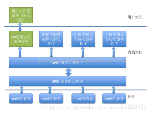
1、SPI控制器驱动程序
SPI控制器不用关心设备的具体功能,它只负责把上层协议驱动准备好的数据按SPI总线的时序要求发送给SPI设备,同时把从设备收到的数据返回给上层的协议驱动,因此,内核把SPI控制器的驱动程序独立出来。SPI控制器驱动负责控制具体的控制器硬件,诸如DMA和中断操作等,因为多个上层的协议驱动可能会通过控制器请求数据传输操作,所以,SPI控制器驱动同时也要负责对这些请求进行队列管理,保证先进先出原则。
2、SPI通用接口封装层
为简化SPI驱动程序编写工作,同时也为了降低协议驱动程序和控制器驱动程序的耦合度,Linux内核把控制器驱动和协议驱动的一些通用操作封装成标准的接口,加上一些通用的逻辑处理操作,组成了SPI通用接口封装层。好处是,对于控制器驱动程序,只要实现标准的接口回调API,并把它注册到通用接口层即可,无需直接和协议层驱动程序进行交互。而对于协议层驱动来说,只需通过通用接口层提供的API即可完成设备和驱动的注册,并通过通用接口层的API完成数据的传输,无需关注SPI控制器驱动的实现细节。
3、SPI协议驱动程序
控制器驱动程序并不清楚和关注设备的具体功能,SPI设备的具体功能是由SPI协议驱动程序完成的,SPI协议驱动程序了解设备的功能和通信数据的协议格式。向下,协议驱动通过通用接口层和控制器交换数据,向上,协议驱动通常会根据设备的具体功能和内核的其它子系统进行交互,例如,和MTD层交互以便把SPI接口的存储设备实现为某个文件系统,和TTY子系统交互把SPI设备实现为一个TTY设备,和网络子系统交互以便把一个SPI设备实现为一个网络设备,等等。如果是一个专有的SPI设备,也可以按照设备的协议要求,实现自己的专有协议驱动。
4、SPI通用设备驱动程序
有时候,考虑到连接在SPI控制器上的设备的可变性,在内核没有配备相应的协议驱动程序,对于这种情况,内核准备了通用的SPI设备驱动程序,该通用设备驱动程序向用户空间提供了控制SPI控制的控制接口,具体的协议控制和数据传输工作交由用户空间根据具体的设备来完成,在这种方式中,只能采用同步的方式和SPI设备进行通信,通常用于一些数据量较少的简单SPI设备。
二、内核驱动SPI相关源码简介----文件框架
SPI驱动由三部分组成,分别是core、master controller driver以及SPI protocol drivers
#
# Makefile for kernel SPI drivers.
#

ccflags-$(CONFIG_SPI_DEBUG) := -DDEBUG

# small core, mostly translating board-specific
# config declarations into driver model code
obj-$(CONFIG_SPI_MASTER)		+= spi.o

# SPI master controller drivers (bus)
obj-$(CONFIG_SPI_ALTERA)		+= spi_altera.o
obj-$(CONFIG_SPI_ATMEL)			+= atmel_spi.o
obj-$(CONFIG_SPI_ATH79)			+= ath79_spi.o
obj-$(CONFIG_SPI_BFIN)			+= spi_bfin5xx.o
。。。。。。。。。。。。。。。。。。。

# special build for s3c24xx spi driver with fiq support
spi_s3c24xx_hw-y			:= spi_s3c24xx.o
spi_s3c24xx_hw-$(CONFIG_SPI_S3C24XX_FIQ) += spi_s3c24xx_fiq.o

# 	... add above this line ...

# SPI protocol drivers (device/link on bus)
obj-$(CONFIG_SPI_SPIDEV)	+= spidev.o
obj-$(CONFIG_SPI_TLE62X0)	+= tle62x0.o
# 	... add above this line ...

# SPI slave controller drivers (upstream link)
# 	... add above this line ...

# SPI slave drivers (protocol for that link)
# 	... add above this line ...
因此,需要了解spi.c,spidev.c等几个文件
三、数据结构
先看数据结构:
spi.h
/*借鉴一些大佬的注释,结合2.6.39版本内核注释一部分数据结构*/
/**
 * struct spi_master - interface to SPI master controller
 SPIz主控制器的接口
 * @dev: device interface to this driver 驱动的设备接口
 * @list: link with the global spi_master list 全局链表
 * @bus_num: board-specific (and often SOC-specific) identifier for a
 *	given SPI controller. 总线数目
 * @num_chipselect: chipselects are used to distinguish individual
 *	SPI slaves, and are numbered from zero to num_chipselects.
 *	each slave has a chipselect signal, but it's common that not
 *	every chipselect is connected to a slave.片选数目
 * @dma_alignment: SPI controller constraint on DMA buffers alignment.dma
 * @mode_bits: flags understood by this controller driver 模式标志位
 * @flags: other constraints relevant to this driver
 * @bus_lock_spinlock: spinlock for SPI bus locking 总线自旋锁
 * @bus_lock_mutex: mutex for SPI bus locking
 * @bus_lock_flag: indicates that the SPI bus is locked for exclusive use
 * @setup: updates the device mode and clocking records used by a
 *	device's SPI controller; protocol code may call this.  This
 *	must fail if an unrecognized or unsupported mode is requested.
 *	It's always safe to call this unless transfers are pending on
 *	the device whose settings are being modified.
 * @transfer: adds a message to the controller's transfer queue.
 * @cleanup: frees controller-specific state
 *
 * Each SPI master controller can communicate with one or more @spi_device
 * children.  These make a small bus, sharing MOSI, MISO and SCK signals
 * but not chip select signals.  Each device may be configured to use a
 * different clock rate, since those shared signals are ignored unless
 * the chip is selected.
 SPImaster 的作用是与子的SPI设备进行通信
 *
 * The driver for an SPI controller manages access to those devices through
 * a queue of spi_message transactions, copying data between CPU memory and
 * an SPI slave device.  For each such message it queues, it calls the
 * message's completion function when the transaction completes.
 *每个SPI主控制器可以与一个或多个@SPI峎设备通信
*孩子们。它们构成了一个小型总线,共享MOSI、MISO和SCK信号
*但不是芯片选择信号。每个设备可以配置为使用
*不同的时钟速率,因为这些共享信号被忽略,除非
*芯片被选中。
管理者
*
*SPI控制器的驱动程序通过
*spi峎消息事务的队列,在CPU内存和
*SPI从设备。对于它队列中的每个这样的消息,它调用
*事务完成时消息的完成函数。
 */
struct spi_master {
	struct device	dev;/*"/dev/spidev1.1";*/

	struct list_head list;

	/* other than negative (== assign one dynamically), bus_num is fully
	 * board-specific.  usually that simplifies to being SOC-specific.
	 * example:  one SOC has three SPI controllers, numbered 0..2,
	 * and one board's schematics might show it using SPI-2.  software
	 * would normally use bus_num=2 for that controller.
	 */
	s16			bus_num;/*总线数目*/

	/* chipselects will be integral to many controllers; some others
	 * might use board-specific GPIOs.
	 */
	u16			num_chipselect;/*片选*/

	/* some SPI controllers pose alignment requirements on DMAable
	 * buffers; let protocol drivers know about these requirements.
	 */
	u16			dma_alignment;

	/* spi_device.mode flags understood by this controller driver */
	u16			mode_bits;

	/* other constraints relevant to this driver */
	u16			flags;
#define SPI_MASTER_HALF_DUPLEX	BIT(0)		/* can't do full duplex */
#define SPI_MASTER_NO_RX	BIT(1)		/* can't do buffer read */
#define SPI_MASTER_NO_TX	BIT(2)		/* can't do buffer write */

	/* lock and mutex for SPI bus locking */
	spinlock_t		bus_lock_spinlock;
	struct mutex		bus_lock_mutex;

	/* flag indicating that the SPI bus is locked for exclusive use */
	bool			bus_lock_flag;

	/* Setup mode and clock, etc (spi driver may call many times).
	 *
	 * IMPORTANT:  this may be called when transfers to another
	 * device are active.  DO NOT UPDATE SHARED REGISTERS in ways
	 * which could break those transfers.
	 */
	int			(*setup)(struct spi_device *spi);/*函数指针用于设置模式和时钟*/

	/* bidirectional bulk transfers
	 *
	 * + The transfer() method may not sleep; its main role is
	 *   just to add the message to the queue.
	 * + For now there's no remove-from-queue operation, or
	 *   any other request management
	 * + To a given spi_device, message queueing is pure fifo
	 *
	 * + The master's main job is to process its message queue,
	 *   selecting a chip then transferring data
	 * + If there are multiple spi_device children, the i/o queue
	 *   arbitration algorithm is unspecified (round robin, fifo,
	 *   priority, reservations, preemption, etc)
	 *
	 * + Chipselect stays active during the entire message
	 *   (unless modified by spi_transfer.cs_change != 0).
	 * + The message transfers use clock and SPI mode parameters
	 *   previously established by setup() for this device
	 */
	int			(*transfer)(struct spi_device *spi,
						struct spi_message *mesg);

	/* called on release() to free memory provided by spi_master */
	void			(*cleanup)(struct spi_device *spi);
};
/**
spi_device代表一个外围spi设备,由主控制器驱动注册完成后扫描BSP中注册
设备产生的设备链表并向spi_bus注册产生。在Linux内核中,每个spi_device代表一个物理的spi设备。
*struct spi_device-spi从设备的主端代理
*@dev:Driver模型表示设备。
*@master:SPI控制器与设备一起使用。
*@max_speed_hz:此芯片使用的最大时钟速率
*(在本板上);可由设备驱动程序更改。
*spi公司_传输速度_hz可以为每个传输覆盖此项。
*@chip_select:Chipselect,区分@master处理的芯片。
*@mode:spi模式定义数据的时钟输出和输入方式。
*这可能会被设备的驱动程序更改。
*芯片选择模式的“低激活”默认值可以被覆盖
*(通过指定SPI_CS_HIGH)作为“MSB first”的默认值
*传输中的每个字(首先指定SPI_LSB_)。
*@bits_per__字:数据传输涉及一个或多个字;字大小
*像8位或12位是很常见的。内存中的字号是
*两个字节的幂(例如,20位样本使用32位)。
*这可能会被设备的驱动程序更改,或者留在
*默认值(0)表示协议字是8位字节。
*spi公司_每字传输位可以为每个传输覆盖此项。
*@irq:Negative,或传递给request_irq()接收的数字
*从这个设备中断。
*@controller_state:控制器的运行时状态
*@controller_data:控制器的板特定定义,例如
*FIFO初始化参数;从板_信息控制器数据
*@driver的别名
*为了那个名字。这将出现在sysfs“modalias”属性中
*用于驾驶员冷拔,以及用于热插拔的通风口
*
*@spi_设备用于在spi从设备之间交换数据
*(通常是分立芯片)和CPU存储器。
*
*在@dev中,platform_数据用于保存有关此的信息
*对设备的协议驱动程序有意义的设备,但不是
*到它的控制器。一个例子是芯片的标识符
*功能稍有不同的变体;另一个可能是
*关于这个特殊电路板如何连接芯片引脚的信息。
* struct spi_device - Master side proxy for an SPI slave device
* @dev: Driver model representation of the device.
* @master: SPI controller used with the device.
* @max_speed_hz: Maximum clock rate to be used with this chip
* (on this board); may be changed by the device's driver.
* The spi_transfer.speed_hz can override this for each transfer.
* @chip_select: Chipselect, distinguishing chips handled by @master.
* @mode: The spi mode defines how data is clocked out and in.
* This may be changed by the device's driver.
* The "active low" default for chipselect mode can be overridden
* (by specifying SPI_CS_HIGH) as can the "MSB first" default for
* each word in a transfer (by specifying SPI_LSB_FIRST).
* @bits_per_word: Data transfers involve one or more words; word sizes
* like eight or 12 bits are common. In-memory wordsizes are
* powers of two bytes (e.g. 20 bit samples use 32 bits).
* This may be changed by the device's driver, or left at the
* default (0) indicating protocol words are eight bit bytes.
* The spi_transfer.bits_per_word can override this for each transfer.
* @irq: Negative, or the number passed to request_irq() to receive
* interrupts from this device.
* @controller_state: Controller's runtime state
* @controller_data: Board-specific definitions for controller, such as
* FIFO initialization parameters; from board_info.controller_data
* @modalias: Name of the driver to use with this device, or an alias
* for that name. This appears in the sysfs "modalias" attribute
* for driver coldplugging, and in uevents used for hotplugging
*
* A @spi_device is used to interchange data between an SPI slave
* (usually a discrete chip) and CPU memory.
*
* In @dev, the platform_data is used to hold information about this
* device that's meaningful to the device's protocol driver, but not
* to its controller. One example might be an identifier for a chip
* variant with slightly different functionality; another might be
* information about how this particular board wires the chip's pins.
*/
struct spi_device {
struct device dev;
struct spi_master *master;
u32 max_speed_hz;
u8 chip_select;
u8 mode;
#define SPI_CPHA 0x01 /* clock phase */
#define SPI_CPOL 0x02 /* clock polarity */
#define SPI_MODE_0 (0|0) /* (original MicroWire) */
#define SPI_MODE_1 (0|SPI_CPHA)
#define SPI_MODE_2 (SPI_CPOL|0)
#define SPI_MODE_3 (SPI_CPOL|SPI_CPHA)
#define SPI_CS_HIGH 0x04 /* chipselect active high? */
#define SPI_LSB_FIRST 0x08 /* per-word bits-on-wire */
#define SPI_3WIRE 0x10 /* SI/SO signals shared */
#define SPI_LOOP 0x20 /* loopback mode */
#define SPI_NO_CS 0x40 /* 1 dev/bus, no chipselect */
#define SPI_READY 0x80 /* slave pulls low to pause */
u8 bits_per_word;
int irq;
void *controller_state;
void *controller_data;
char modalias[SPI_NAME_SIZE];
/*
* likely need more hooks for more protocol options affecting how
* the controller talks to each chip, like:
* - memory packing (12 bit samples into low bits, others zeroed)
* - priority
* - drop chipselect after each word
* - chipselect delays
* - ...
*/
};/**
* struct spi_driver - Host side "protocol" driver
* @id_table: List of SPI devices supported by this driver
* @probe: Binds this driver to the spi device. Drivers can verify
* that the device is actually present, and may need to configure
* characteristics (such as bits_per_word) which weren't needed for
* the initial configuration done during system setup.
* @remove: Unbinds this driver from the spi device
* @shutdown: Standard shutdown callback used during system state
* transitions such as powerdown/halt and kexec
* @suspend: Standard suspend callback used during system state transitions
* @resume: Standard resume callback used during system state transitions
* @driver: SPI device drivers should initialize the name and owner
* field of this structure.
*
* This represents the kind of device driver that uses SPI messages to
* interact with the hardware at the other end of a SPI link. It's called
* a "protocol" driver because it works through messages rather than talking
* directly to SPI hardware (which is what the underlying SPI controller
* driver does to pass those messages). These protocols are defined in the
* specification for the device(s) supported by the driver.
*
* As a rule, those device protocols represent the lowest level interface
* supported by a driver, and it will support upper level interfaces too.
* Examples of such upper levels include frameworks like MTD, networking,
* MMC, RTC, filesystem character device nodes, and hardware monitoring.
*struct spi_驱动程序主机端“协议”驱动程序
*@id_table:此驱动程序支持的SPI设备列表
*@probe:将这个驱动程序绑定到spi设备。驾驶员可以验证
*设备实际存在,可能需要配置
*不需要的特征(例如每个单词的位数)
*在系统设置期间完成的初始配置。
*@remove:将此驱动程序从spi设备上解除绑定
*@shutdown:系统状态期间使用的标准关机回调
*断电/停机和kexec等转换
*@suspend:在系统状态转换期间使用的标准挂起回调
*@resume:在系统状态转换期间使用的标准恢复回调
*@driver:SPI设备驱动程序应该初始化名称和所有者
*这个结构的场。
*
*这表示使用SPI消息来
*与SPI链路另一端的硬件交互。它叫
*一个“协议”驱动程序,因为它通过消息而不是对话工作
*直接到SPI硬件(这是底层SPI控制器
*司机会传递这些信息)。这些协议在
*驱动程序支持的设备的规范。
*
*通常,这些设备协议代表最低级别的接口
*由驱动程序支持,它也将支持上层接口。
*这类高层的例子包括MTD,networking等框架,
*MMC、RTC、文件系统字符设备节点和硬件监视。
*/
struct spi_driver {
const struct spi_device_id *id_table;
int (*probe)(struct spi_device *spi);
int (*remove)(struct spi_device *spi);
void (*shutdown)(struct spi_device *spi);
int (*suspend)(struct spi_device *spi, pm_message_t mesg);
int (*resume)(struct spi_device *spi);
struct device_driver driver;
};/*
*SPI控制器与协议驱动程序之间的I/O接口
*
*使用每个spi协议传输数据驱动程序
*在控制器和内存缓冲区之间。
*
*spiđu消息本身包含一系列读写传输
*分段。这些段总是读取与它们相同的位数
*写入;但是传递一个空缓冲区很容易忽略其中一个
*指针。(这与大多数类型的I/O API不同,因为SPI硬件
*是全双工。)
*
*注:spi传输和spi消息存储器的分配完全是
*直到协议驱动程序,它保证了两者的完整性(如
*以及数据缓冲区)。
*/
/**
*struct spi_transfer-读/写缓冲区对
*@tx_buf:要写入的数据(dma安全内存),或为空
*@rx_buf:要读取的数据(dma安全内存),或为空
*@tx_dma:tx_buf的dma地址,如果@spi_message.is_dma_映射
*@rx_dma:rx_buf的dma地址,如果@spi_message.is_dma_映射
*@len:rx和tx缓冲区的大小(字节)
*@speed_hz:为此选择设备默认值以外的速度
*转移。如果为0,则使用默认值(来自@spi_设备)。
*@bits_per_字:选择设备默认值以外的每个字位
*为了这次转移。如果为0,则使用默认值(来自@spi_设备)。
*@cs_change:在传输完成后影响chipselect
*@delay_usecs:
*(可选)更改芯片选择状态,然后启动
*下一次传输或完成此@spi嫒消息。
*@transfer_list:传输通过@spi排序_信息传输
*
*SPI传输总是写入与读取相同数量的字节。
*协议驱动程序应始终提供@rx_buf和/或@tx_buf。
*在某些情况下,他们可能还想为
*正在传输的数据;当
*底层驱动程序使用dma。
*
*如果传输缓冲区为空,则零将被移出
*当填充@rx_buf时。如果接收缓冲区为空,则数据
*换班将被丢弃。只有“len”字节向外(或向内)移位。
*试图去掉部分单词是错误的。(例如,通过
*移位3个字节,字大小为16或20位;
*前者每个字使用两个字节,后者使用四个字节。)
*
*内存中的数据值总是按本机CPU字节顺序进行转换
*从线字节顺序(big-endian,但SPI逯LSB_优先)。所以
*例如,当每字位_为16时,缓冲区的长度为2N字节
*(@len=2N)并按CPU字节顺序保存N个16位字。
*
*当SPI传输的字大小不是2的幂次方时
*在8位中,那些在内存中的字包括额外的位。记忆中
*协议驱动程序总是认为单词是正确的,因此
*未定义(rx)或未使用(tx)位始终是最有效的位。
*
*所有SPI传输都是在相关的chipselect激活时开始的。正常情况下
*在最后一条消息之后,它将保持选定状态。司机
*会影响使用cs_change的chipselect信号。
*
*(i)如果传输不是消息中的最后一个,则此标志为
*用于使芯片选择在
*留言。以这种方式切换chipselect可能需要终止
*一种芯片命令,允许单个spi峎消息执行组
*芯片交易在一起。
*
*(ii)当传输是消息中的最后一个传输时,芯片可以
*保持选中状态直到下一次传输。多设备SPI总线
*由于没有阻止消息发送到其他设备,这只是
*性能提示;向另一个设备发送消息取消选择
*这个。但在其他情况下,这可以用来确保正确性。
*需要从一系列设备中构建一系列的协议
*spi_消息提交,其中确定一条消息的内容
*根据之前消息的结果以及整个事务
*当chipselect激活时结束。
*
*提交spi峎u消息(及其spi峎u传输)的代码
*下层负责管理其内存。
*零初始化每个未显式设置的字段,以
*与将来的API更新隔离。在您提交消息后
*以及它的传输,忽略它们直到完成回调。
*/
struct spi_transfer {
/* it's ok if tx_buf == rx_buf (right?)
* for MicroWire, one buffer must be null
* buffers must work with dma_*map_single() calls, unless
* spi_message.is_dma_mapped reports a pre-existing mapping
*/
const void *tx_buf;
void *rx_buf;
unsigned len;
dma_addr_t tx_dma;
dma_addr_t rx_dma;
unsigned cs_change:1;
u8 bits_per_word;
u16 delay_usecs;
u32 speed_hz;
struct list_head transfer_list;
};

SPI通信
http://blog.chinaunix.net/uid-27570663-id-3323955.html
https://blog.csdn.net/weixin_42015463/article/details/81430494
<从设备驱动层> spidev.c 自己编写
<核 心 层> spi.c 内核提供
<控 制 器 层> spi-xxx.c(瑞芯微:spi-rockchip.c 全志:spi-sunxi.c) 原厂提供
先看spi.c
直接找驱动入口:
static int __init spi_init(void)


 450
450

 被折叠的 条评论
为什么被折叠?
被折叠的 条评论
为什么被折叠?
 到【灌水乐园】发言


