


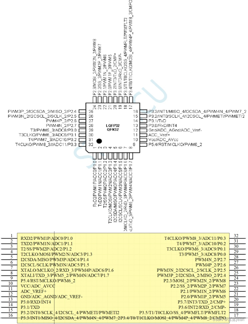
1.STC 8h1k28单片机引脚(pin)
STC8h1k28这款单片机芯片由32个引脚组成,分别对应下图所示
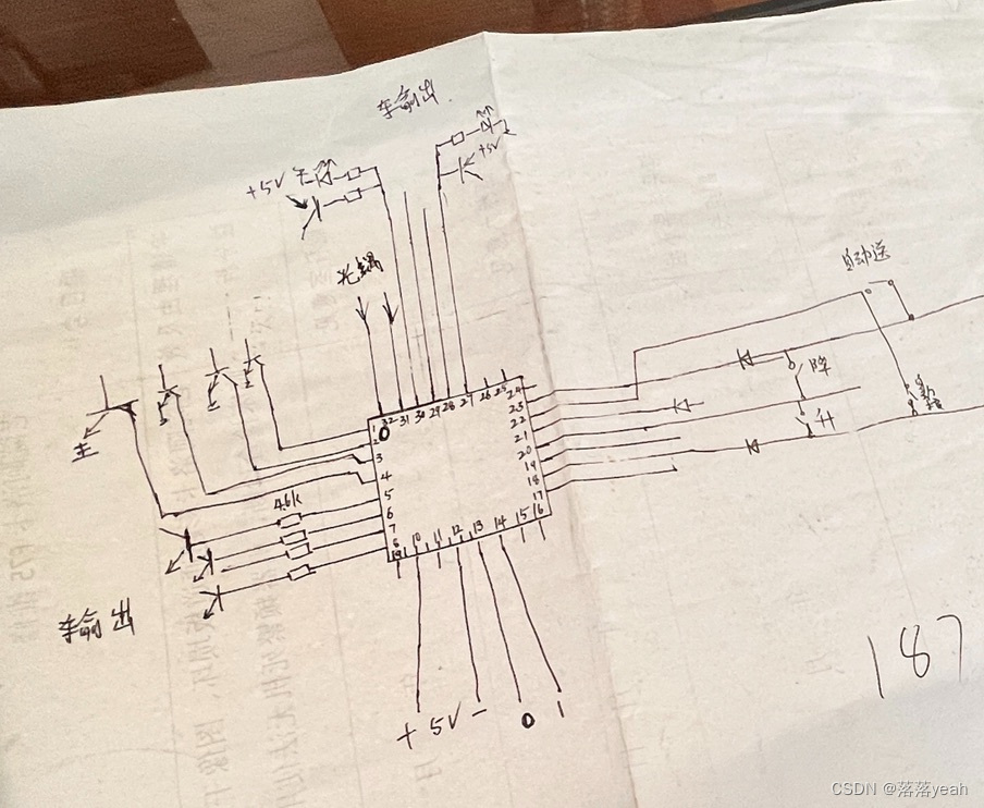
2.原理图
3.相关的C语言代码(来源于Chatgpt🌚)
#include <reg51.h> // Include STC 8H1k28 specific header file
// Define pin mappings
#define PIN_22 P1_0 // Input from switch
#define PIN_20 P1_1 // Input from rising switch
#define PIN_18 P1_2 // Input from falling switch
#define PIN_23 P1_3 // Input from middle switch
#define PIN_21 P1_4 // Input from end diode
#define PIN_1 P2_0 // Output to Transistor
#define PIN_2 P2_1 // Output to Transistor
#define PIN_3 P2_2 // Output to Transistor
#define PIN_4 P2_3 // Output to Transistor
#define PIN_5 P2_4 // Output to Transistor with resistor
#define PIN_6 P2_5 // Output to Transistor with resistor
#define PIN_7 P2_6 // Output to resistor
#define PIN_8 P2_7 // Output to Transistor with resistor
#define PIN_27 P3_6 // Output to photodiode
#define PIN_30 P3_7 // Output to photodiode
#define PIN_31 P4_0 // Output to optical coupler
#define PIN_32 P4_1 // Output to optical coupler
void main() {
// Initialize ports
P1 = 0xFF; // Configure Port 1 as input
P2 = 0x00; // Configure Port 2 as output
P3 = 0x00; // Configure Port 3 as output
P4 = 0x00; // Configure Port 4 as output
// Set initial values
P2 &= 0xF0; // Clear lower nibble of Port 2
// Main loop
while (1) {
// Read inputs
bit switch_input = PIN_22;
bit middle_switch_input = PIN_23;
bit end_diode_input = PIN_21;
bit rising_switch_input = PIN_20;
bit falling_switch_input = PIN_18;
// Process inputs as needed
// Example: Toggle outputs based on inputs
if (switch_input == 0) {
PIN_1 ^= 1;
PIN_2 ^= 1;
PIN_3 ^= 1;
PIN_4 ^= 1;
}
if (middle_switch_input == 0 && end_diode_input == 1) {
PIN_5 ^= 1;
PIN_6 ^= 1;
PIN_7 ^= 1;
PIN_8 ^= 1;
}
if (rising_switch_input == 1 && falling_switch_input == 0) {
PIN_27 ^= 1;
PIN_30 ^= 1;
}
// Example: Set optical coupler outputs
PIN_31 = 1; // Example: Set pin 31 high
PIN_32 = 0; // Example: Set pin 32 low
// Delay or additional processing as needed
// Example delay
for (int i = 0; i < 10000; i++) {
for (int j = 0; j < 100; j++) {
// Delay loop
}
}
}
}


 1010
1010

 被折叠的 条评论
为什么被折叠?
被折叠的 条评论
为什么被折叠?
 到【灌水乐园】发言


