


 本文介绍了如何在FPGA设计中利用线性序列机和状态机思想实现数据发送。具体地,通过一个50个时钟周期发送一字节数据的data_send模块和一个控制发送间隔的ctrl模块,确保每5000ns发送一次数据。文章详细展示了这两个模块的Verilog代码及仿真过程,并指出在ctrl模块中存在3个时钟周期的延迟问题,提出了优化方案。
在FPGA设计中,线性序列机和状态机思想是十分重要的思想方法,用于实现各种时序要求。这次的内容是实现用FPGA,时钟周期为20ns,每间隔5000ns发送一个字节的数据,数据不从外部接入,而是内部给定。本着模块化设计原则,整体结构如下:
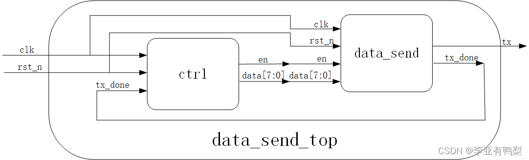
子模块为ctrl和data_send,顶层为data_send_top。
data_send模块在en信号的同步下实现数据的发送,每50个时钟周期发送一个bit,发送完成后拉高一个时钟周期的tx_done。
ctrl模块根据tx_done信号来控制数据发送的间隔,同时指定要发送的数据data。
一、data_send设计与仿真
逻辑设计
对于data_send要求50个时钟周期发一个bit,采用线性序列机实现,实现一个最大值为50个时钟周期的计数器1,再实现一个对计数器1的溢出次数进行计数的计数器2,是个模8计数器(但为了生成tx_done以及不在0时刻发送data数据,这里实现的是模9计数器),后面的逻辑根据计数器2的计数值按时将数据放在数据线上即可。这就是线性序列机的思想,在实际应用中,往往要生成一组信号来满足某些控制器的时序,可以找到这些信号的变化最小时间单位,类似得实现计数器1,再实现计数器2,最后根据时序灵活安排数据发送得时刻即可。
module data_send
(
    input       wire                clk     ,
    input       wire                rst_n   ,
    input       wire                en      ,
    input       wire    [7:0]       data    ,

    output      reg                 tx      ,
    output      wire                tx_done
);


reg     [7:0]   cnt;//计数器1
reg     [4:0]   cnt_add; //计数器2

always@(posedge clk or negedge rst_n)
    if(!rst_n)
        cnt <= 8'd0;
    else if(en)
        if(cnt == 8'd49)
            cnt <= 8'd0;
        else
            cnt <= cnt + 1'b1;
    else
        cnt <= 8'd0;


always@(posedge clk or negedge rst_n)
    if(!rst_n)
        cnt_add <= 5'd0;
    else if(en) begin
        if(cnt_add == 5'd9)
            cnt_add <= 5'd0;
        else if(cnt == 8'd49)
            cnt_add <= cnt_add + 1'b1;
    end
    else
        cnt_add <= 5'd0;

//序列机实现
always@(posedge clk or negedge rst_n)
    if(!rst_n)
        tx <= 1'b0;
    else
        case(cnt_add)
            5'd1 : tx <= data[0];
            5'd2 : tx <= data[1];
            5'd3 : tx <= data[2];
            5'd4 : tx <= data[3];
            5'd5 : tx <= data[4];
            5'd6 : tx <= data[5];
            5'd7 : tx <= data[6];
            5'd8 : tx <= data[7];
            default : tx <= 1'b0;
        endcase

//tx_done信号生成
always@(posedge clk or negedge rst_n)
    if(!rst_n)
        tx_done <= 1'b0;
    else if(cnt_add == 5'd9)
        tx_done <= 1'b1;
    else
        tx_done <= 1'b0;

endmodule
tb
`timescale 1ns/1ns
`define clk_period 20
module data_send_tb;

//============================<端口>==============================
reg clk;
reg rst_n;
reg en;
reg [7:0] data;

wire    tx;
wire    tx_done;
//================================================================
//==                         模块例化
//================================================================
data_send data_send_inst0
(
    .clk     (clk),
    .rst_n   (rst_n),
    .en      (en),
    .data    (data),

    .tx      (tx),
    .tx_done (tx_done)
);


//================================================================
//==                         时钟信号
//================================================================
initial clk = 1'b1;
always #(`clk_period/2) clk = ~clk;

//================================================================
//==                       设计输入信号
//================================================================
initial begin
    rst_n = 0;
    en = 0;
    data = 8'h00;
    #201;
    rst_n = 1;
    #201;
    data = 8'h23;
    en = 1;
    #20000;
    en = 0;
    #5000;

    data = 8'h56;
    en = 1;
    #20000;
    en = 0;
    #5000;
    $stop;

end

endmodule
modelsim仿真
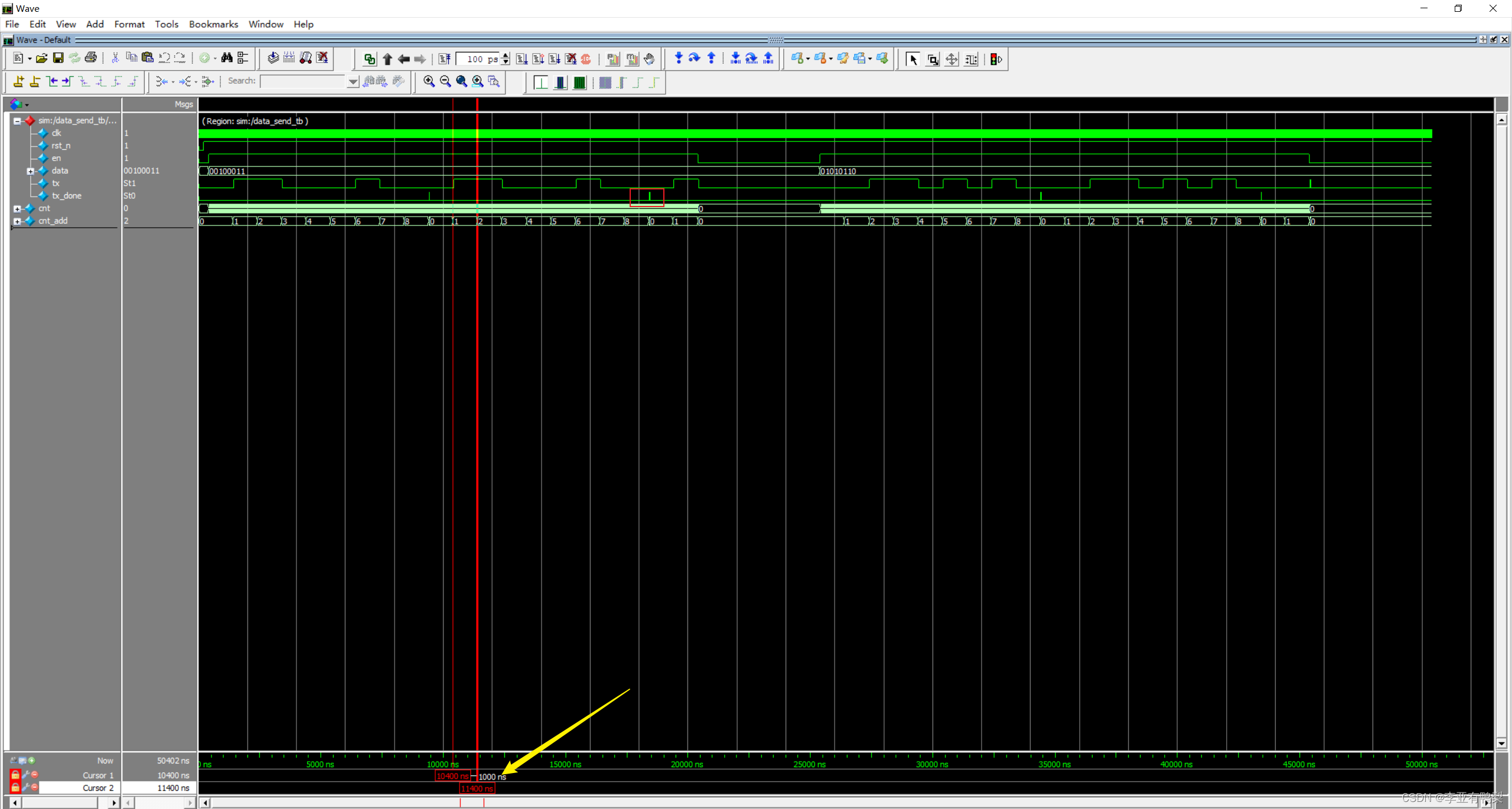
可以看到,发送完第八个字节后,拉高了一个时钟周期的tx_done,测量一个bit发送时间为50*20=1000ns,符合设计要求。
二、ctrl模块设计与仿真
逻辑设计
在这个模块中,由于tx_done信号需要data_send模块产生,而data_send需要ctrl的en信号来启动发送,故采用状态机来实现ctrl模块。
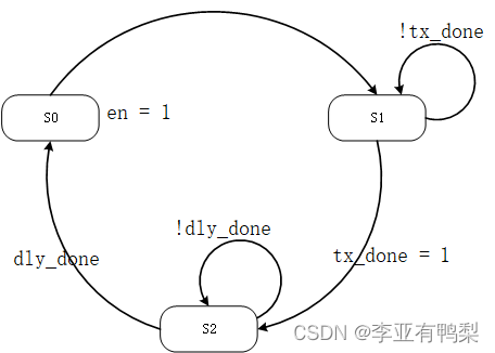
S0中en = 1,让data_send模块工作。
S1中等待tx_done信号有效。
S2中等待5000ns(250个时钟周期)。
module ctrl
(
    input       wire            clk     ,
    input       wire            rst_n   ,
    input       wire            tx_done ,

    output      reg             en      ,
    output      reg    [7:0]    data
);

reg [11:0]  cnt; //50us计数器
reg         cnt_en;
reg         dly_done;
reg [1:0]   state;
localparam  S0 = 3'd0;
localparam  S1 = 3'd1;
localparam  S2 = 3'd2;

always@(posedge clk or negedge rst_n)
    if(!rst_n)begin
        state <= S0;
        cnt_en <= 1'b0;
        en <= 1'b0;
        data <= 8'd0;
    end
    else begin
        case(state)
            S0 : begin
                en = 1'b1 ;
                data <= 8'h12;
                state <= S1;
            end
            S1 : begin
                if(tx_done) begin
                    state <= S2;
                    cnt_en <= 1;
                    en <= 0;
                end
                else begin
                    en <= 1;
                    cnt_en <= 0;
                    state <= S1;
                end
            end
            S2 : begin
                if(!dly_done) begin
                    state <= S2;
                    cnt_en <= 1;
                end
                else begin
                    cnt_en = 0;
                    state <= S0;
                end
            end
            default : begin
                state <= S0;
                cnt_en <= 0;
                en = 0;
            end
        endcase
    end


always@(posedge clk or negedge rst_n)
    if(!rst_n)
        cnt <= 12'd0;
    else if(cnt_en)begin
        if(cnt == 12'd249)
            cnt <= 12'd0;
        else
            cnt <= cnt + 1'b1;
    end
    else
        cnt <= 12'd0;

always@(posedge clk or negedge rst_n)
    if(!rst_n)
        dly_done <= 1'b0;
    else if(cnt == 12'd249)
        dly_done <= 1'b1;
    else
        dly_done <= 1'b0;


endmodule
tb
`timescale 1ns/1ns
`define clk_period 20
module ctrl_tb;

//============================<端口>==============================
reg clk;
reg rst_n;
reg tx_done;

wire    en;
wire    [7:0] data;
//================================================================
//==                         模块例化
//================================================================
ctrl ctrl_inst0
(
    .clk     (clk),
    .rst_n   (rst_n),
    .tx_done (tx_done),

    .en      (en),
    .data    (data)
);


//================================================================
//==                         时钟信号
//================================================================
initial clk = 1'b1;
always #(`clk_period/2) clk = ~clk;

//================================================================
//==                       设计输入信号
//================================================================
initial begin
    rst_n = 0;
    tx_done = 0;
    #201;
    rst_n = 1;

    #201;
    tx_done = 1;
    #20;
    tx_done = 0;
    #8000;

    tx_done = 1;
    #20;
    tx_done = 0;
    #8000;
    $stop;

end

endmodule
modelsim仿真
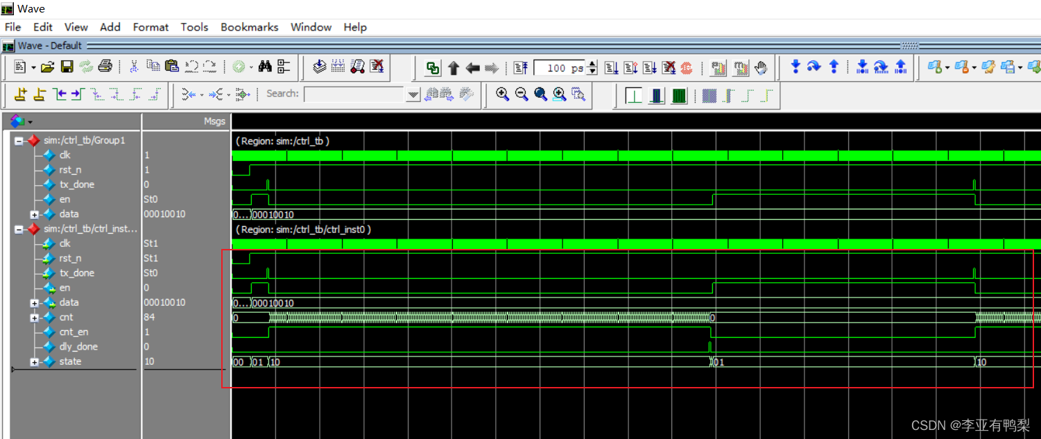
可以看到,状态机可以正常工作。
三、ctrl模块设计与仿真
按照架构图在data_send_top例化即可。
逻辑设计
module data_send_top
(
    input       wire        clk         ,
    input       wire        rst_n       ,

    output      wire        tx
);

wire    en;
wire    [7:0] data;
wire    tx_done;

data_send data_send_inst0
(
    .clk     (clk),
    .rst_n   (rst_n),
    .en      (en),
    .data    (data),

    .tx      (tx),
    .tx_done (tx_done)
);


ctrl ctrl_inst0
(
    .clk     (clk),
    .rst_n   (rst_n),
    .tx_done (tx_done),

    .en      (en),
    .data    (data)
);

endmodule
tb
`timescale 1ns/1ns
`define clk_period 20
module data_send_top_tb;

//============================<端口>==============================
reg clk;
reg rst_n;

wire    tx;
//================================================================
//==                         模块例化
//================================================================
data_send_top data_send_top_inst
(
    .clk         (clk),
    .rst_n       (rst_n),

    .tx          (tx)
);


//================================================================
//==                         时钟信号
//================================================================
initial clk = 1'b1;
always #(`clk_period/2) clk = ~clk;

//================================================================
//==                       设计输入信号
//================================================================
initial begin
    rst_n = 0;
    #201;
    rst_n = 1;
    #200000;

end

endmodule
modelsim仿真
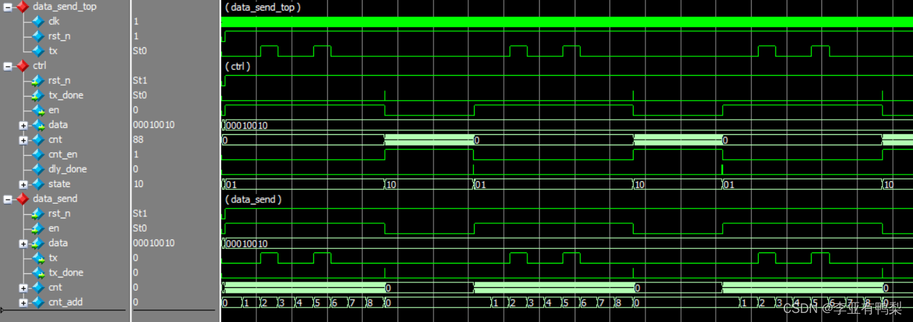
仔细观察,发现整体是可以正常工作的。
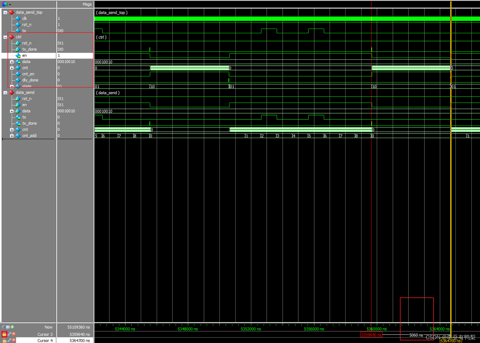
优化
在观察中,发现在ctrl中,从tx_done信号为高到发出en = 1信号,时间并不是严格的5000ns,而是多了3个时钟周期。
观察到dly_done信号是用时序逻辑实现会延迟一个时钟,但该信号的意义因该是计数到时立即有效,故用组合逻辑实现。结果优化了20ns。
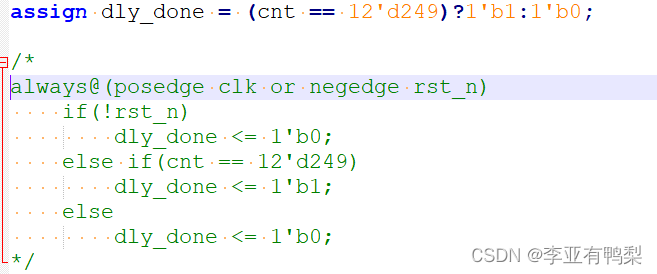
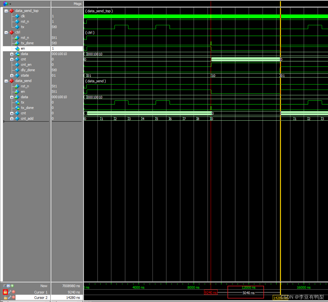
但还是存在优化空间。
四、总结
了解了线性序列机和状态机的思想和基本实现方法。
写子模块时必须要仿真验证通过才能进行下一步工作,否则之后的步骤中的错误将很难排查。
写代码之前最好将思路想好,模块分好,照图施工。


 335
335

 被折叠的 条评论
为什么被折叠?
被折叠的 条评论
为什么被折叠?
 到【灌水乐园】发言


