STM32L475潘多拉开发板RT Thread实验3_按键输入例程

一、头文件讲述:

#include <rtthread.h>
#include <rtdevice.h>
#include <board.h>
#define DBG_TAG "main"
#define DBG_LVL DBG_LOG
#include <rtdbg.h>

这次的这些头文件中,还是和之前那两个实验一样的功能,就不过多讲述了,主要要说的地方就是找到按键引脚定义的地方。

首先我们打开Divers文件夹,打开里面的drv_gpio.c文件,可以看到很多引脚区域的定义,找到这部分代码:

    __STM32_PIN(55,  D, 7),
    __STM32_PIN(56,  D, 8),
    __STM32_PIN(57,  D, 9),
    __STM32_PIN(58,  D, 10),

这个代码是定义按键的四个引脚的,然后我们打开drv_gpio.h,然后可以看到定义的具体内容:

#define PIN_KEY2        GET_PIN(D, 8)      // PD8 :  KEY2         --> KEY
#define PIN_KEY1        GET_PIN(D, 9)      // PD9 :  KEY1         --> KEY
#define PIN_KEY0        GET_PIN(D, 10)     // PD10:  KEY0         --> KEY
#define PIN_WK_UP       GET_PIN(C, 13)     // PC13:  WK_UP        --> KEY

 现在我们只需要在主函数中使用这些代码就行。

二、主函数

(1)主函数

首先来看看按键的一些电路原理:

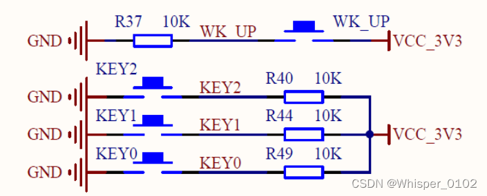
 在这张电路图中,由于WK_UP按键和其他三个按键的原理电路不一样,所以WK_UP按键是按下为高电平,不按为高电平,其他三个按键KEY0~2是按下为低电平,不按为高电平。

int main(void)
{
    unsigned int count = 1;

    /* 设置 RGB 红灯引脚的模式为输出模式 */
    rt_pin_mode(PIN_LED_R, PIN_MODE_OUTPUT);
    /* 设置 KEY0 引脚的模式为输入模式 */
    rt_pin_mode(PIN_KEY0, PIN_MODE_INPUT);

    while (count > 0)
    {
        /* 读取按键 KEY0 的引脚状态 */
        if (rt_pin_read(PIN_KEY0) == PIN_LOW)
        {
            rt_thread_mdelay(50);
            if (rt_pin_read(PIN_KEY0) == PIN_LOW)
            {
                /* 按键已被按下,输出 log,点亮 LED 灯 */
                LOG_D("KEY0 pressed!");
                rt_pin_write(PIN_LED_R, PIN_LOW);
            }
        }
        else
        {
            /* 按键没被按下,熄灭 LED 灯 */
            rt_pin_write(PIN_LED_R, PIN_HIGH);
        }
        rt_thread_mdelay(10);
        count++;
    }
    return 0;
}

在这个代码中,首先先设置 KEY0 引脚为输入模式,R 灯引脚为输出模式,所以在 if 函数中首先先按键消抖判断是否按下,如果按下则 KEY0 引脚为低电平,则写 R 灯引脚电平为低电平,灯点亮,否则 R 灯引脚始终为高电平不点亮。

(2)拓展

现在我改一下例程代码,使得四个按键都有相应的功能,现在的功能是:

KEY0:R 灯亮;

KEY1:G 灯亮;

KEY2:B 灯亮;

WK_UP:R G B 三灯全亮。

但需要注意的是,WK_UP 引脚是按下为高,不按为低,和其他三个按键的原理不一样。

int main(void)
{
    /* 设置 RGB 红灯引脚的模式为输出模式 */
    rt_pin_mode(PIN_LED_R, PIN_MODE_OUTPUT);
		rt_pin_mode(PIN_LED_G, PIN_MODE_OUTPUT);
		rt_pin_mode(PIN_LED_B, PIN_MODE_OUTPUT);
    /* 设置 KEY0 引脚的模式为输入模式 */
    rt_pin_mode(PIN_KEY0, PIN_MODE_INPUT);
		rt_pin_mode(PIN_KEY1, PIN_MODE_INPUT);
		rt_pin_mode(PIN_KEY2, PIN_MODE_INPUT);
	  rt_pin_mode(PIN_WK_UP, PIN_MODE_INPUT);

    while (1)
    {
        /* 读取按键 KEY0 的引脚状态 */
        if (rt_pin_read(PIN_KEY0) == PIN_LOW)
        {
            rt_thread_mdelay(50);
            while (rt_pin_read(PIN_KEY0) == PIN_LOW)
            {
                /* 按键已被按下,输出 log,点亮 LED 灯 */
                LOG_D("KEY0 pressed!");
                rt_pin_write(PIN_LED_R, PIN_LOW);
            }
        }
        else
        {
            /* 按键没被按下,熄灭 LED 灯 */
            rt_pin_write(PIN_LED_R, PIN_HIGH);
        }
        rt_thread_mdelay(10);
				
				/* 读取按键 KEY1 的引脚状态 */
        if (rt_pin_read(PIN_KEY1) == PIN_LOW)
        {
            rt_thread_mdelay(50);
            while (rt_pin_read(PIN_KEY1) == PIN_LOW)
            {
                /* 按键已被按下,输出 log,点亮 LED 灯 */
                LOG_D("KEY1 pressed!");
                rt_pin_write(PIN_LED_G, PIN_LOW);
            }
        }
        else
        {
            /* 按键没被按下,熄灭 LED 灯 */
            rt_pin_write(PIN_LED_B, PIN_HIGH);
        }
        rt_thread_mdelay(10);
				
				/* 读取按键 KEY2 的引脚状态 */
        if (rt_pin_read(PIN_KEY2) == PIN_LOW)
        {
            rt_thread_mdelay(50);
            while (rt_pin_read(PIN_KEY2) == PIN_LOW)
            {
                /* 按键已被按下,输出 log,点亮 LED 灯 */
                LOG_D("KEY2 pressed!");
                rt_pin_write(PIN_LED_B, PIN_LOW);
            }
        }
        else
        {
            /* 按键没被按下,熄灭 LED 灯 */
            rt_pin_write(PIN_LED_B, PIN_HIGH);
        }
        rt_thread_mdelay(10);
				
				/* 读取按键 WK_UP 的引脚状态 */
        if (rt_pin_read(PIN_WK_UP) == PIN_HIGH)
        {
            rt_thread_mdelay(50);
            while (rt_pin_read(PIN_WK_UP) == PIN_HIGH)
            {
                /* 按键已被按下,输出 log,点亮 LED 灯 */
                LOG_D("WK_UP pressed!");
                rt_pin_write(PIN_LED_R, PIN_LOW);
								rt_pin_write(PIN_LED_G, PIN_LOW);
								rt_pin_write(PIN_LED_B, PIN_LOW);
            }
        }
        else
        {
            /* 按键没被按下,熄灭 LED 灯 */
            rt_pin_write(PIN_LED_R, PIN_HIGH);
						rt_pin_write(PIN_LED_G, PIN_HIGH);
						rt_pin_write(PIN_LED_B, PIN_HIGH);
        }
        rt_thread_mdelay(10);
    }
    return 0;
}

  • 3
    点赞
  • 6
    收藏
    觉得还不错? 一键收藏
  • 0
    评论
好的,下面是基于潘多开发rt_thread操作系统读取ap3216传感器的代码,希望能对你有帮助。 ```c #include <rtthread.h> #include <rtdevice.h> #include "ap3216c.h" #define AP3216C_I2C_ADDR 0x1E /* AP3216C I2C address */ #define AP3216C_REG_ID 0x00 /* AP3216C ID register address */ #define AP3216C_REG_DATA 0x03 /* AP3216C data register address */ /* AP3216C I2C bus device */ static struct rt_i2c_bus_device *i2c_bus; /* Initialize AP3216C */ static rt_err_t ap3216c_init(void) { rt_uint8_t id; /* Check AP3216C ID */ rt_uint8_t reg = AP3216C_REG_ID; rt_err_t ret = rt_i2c_master_send(i2c_bus, AP3216C_I2C_ADDR, &reg, 1); if (ret != RT_EOK) { rt_kprintf("Failed to send ID register address!\n"); return RT_ERROR; } ret = rt_i2c_master_recv(i2c_bus, AP3216C_I2C_ADDR, &id, 1); if (ret != RT_EOK) { rt_kprintf("Failed to receive ID register value!\n"); return RT_ERROR; } if (id != 0x16) { rt_kprintf("Invalid AP3216C ID: 0x%02x!\n", id); return RT_ERROR; } /* Initialize AP3216C */ ret = ap3216c_init(i2c_bus); if (ret != RT_EOK) { rt_kprintf("Failed to initialize AP3216C!\n"); return RT_ERROR; } return RT_EOK; } /* AP3216C reading thread */ static void ap3216c_thread_entry(void *parameter) { rt_uint16_t ir, als, ps; while (1) { /* Read data from AP3216C */ rt_err_t ret = ap3216c_read_data(i2c_bus, &ir, &als, &ps); if (ret != RT_EOK) { rt_kprintf("Failed to read data from AP3216C!\n"); continue; } /* Print data */ rt_kprintf("IR: %d, ALS: %d, PS: %d\n", ir, als, ps); /* Delay for 1 second */ rt_thread_mdelay(1000); } } /* AP3216C demo entry */ int ap3216c_demo(void) { /* Open I2C bus device */ i2c_bus = (struct rt_i2c_bus_device *)rt_device_find("i2c1"); if (i2c_bus == RT_NULL) { rt_kprintf("Failed to find I2C bus device!\n"); return -RT_ERROR; } rt_err_t ret = rt_device_open((rt_device_t)i2c_bus, RT_DEVICE_FLAG_RDWR); if (ret != RT_EOK) { rt_kprintf("Failed to open I2C bus device!\n"); return -RT_ERROR; } /* Initialize AP3216C */ ret = ap3216c_init(); if (ret != RT_EOK) { rt_kprintf("Failed to initialize AP3216C!\n"); return -RT_ERROR; } /* Create AP3216C reading thread */ rt_thread_t thread = rt_thread_create("ap3216c", ap3216c_thread_entry, RT_NULL, 1024, 25, 10); if (thread == RT_NULL) { rt_kprintf("Failed to create AP3216C reading thread!\n"); return -RT_ERROR; } rt_thread_startup(thread); return RT_EOK; } ``` 该代码首先定义了AP3216C的I2C地址和寄存器地址,然后通过ap3216c_init函数初始化AP3216C。接着,创建一个线程来读取AP3216C的数据,将读取到的数据打印出来,并延时1秒钟。 在ap3216c_demo函数中,首先找到I2C总线设备,然后打开该设备。接着,调用ap3216c_init函数初始化AP3216C,并创建一个线程来读取AP3216C的数据。 请注意,该代码仅供参考,实际使用时需要根据具体情况进行修改和适配。

“相关推荐”对你有帮助么?

  • 非常没帮助
  • 没帮助
  • 一般
  • 有帮助
  • 非常有帮助
提交
评论
添加红包

请填写红包祝福语或标题

红包个数最小为10个

红包金额最低5元

当前余额3.43前往充值 >
需支付:10.00
成就一亿技术人!
领取后你会自动成为博主和红包主的粉丝 规则
hope_wisdom
发出的红包
实付
使用余额支付
点击重新获取
扫码支付
钱包余额 0

抵扣说明:

1.余额是钱包充值的虚拟货币,按照1:1的比例进行支付金额的抵扣。
2.余额无法直接购买下载,可以购买VIP、付费专栏及课程。

余额充值