


ref:http://kylehalladay.com/blog/tutorial/2014/02/18/Fresnel-Shaders-From-The-Ground-Up.html
I recently stumbled on the awesome article: Everything Has Fresnel (if you haven’t read it, go read it now). The main premise of the article is that real world materials are not actually as neat and tidy as programmers would like to believe, and more specifically, that virtually everything in real life has some degree of fresnel reflectivity.
Fresnel isn’t an effect that I’ve seen often in Unity projects and in fact wasn’t an effect that I was familiar with building, so I decided to kill two birds with one project and put together my latest shader pack: Fresnel Shaders. It’s all free to use, MIT license, all that jazz, so enjoy :D
But, as usual, I’d also like to make things a bit easier for the next googler looking for an intro to Fresnel reflection. So if writing Fresnel shaders (or adding Fresnel to existing ones) sounds as much fun to you as it was for me, read on!
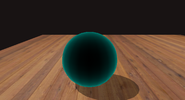
An unlit Fresnel shader
What is the Fresnel Effect
In essence, the fresnel effect describes the relationship between the angle that you look at a surface and the amount of reflectivity you see. This is very easy to demonstrate if you have a window nearby. If you look at the window straight on you can see through the window as intended, however, if you move so that you try to look through the window at a glancing angle (ie: your view direction is approaching parallel to the window’s surface) the window becomes much closer to a mirror.
But this effect isn’t limited to windows, or even particularly shiny objects. As John Hable points out in Everything Has Fresnel, pretty much everything (including towels and bricks!) exhibit the fresnel effect to some degree. I’ve made a game out of trying to spot instances of it as I walk to work (without looking I’ve lost my mind).
So what does this look like when added to an object in Unity? Here’s a few more examples from my shader pack:
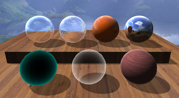
The Shaders in the Fresnel Shader Pack
How is it implemented?
As it turns out, Fresnel equations are complicated, way more so than can be adequately covered by a blog post, and way more than is feasible to execute in real time for most applications. In practice, it’s far more realistic to use an approximation of these equations. In searching, I’ve ended up finding two such approximations have so far seemed appropriate to use in real time shaders.
The first is the Schlick Approximation. This is easy enough to google for, but I’ll put here just for reference as well:
In the above equation, R0 refers to the reflection coefficient for light moving between 2 interfaces with different refractivity (most commonly, air and whatever type of material the surface is). If you’re really interested, definitely check out more detailed sources online. In practice, I’ve found that while this method gives decent looking results, the next option gives us much greater control over the appearance of our materials at the cost of physical correctness. Given that real time graphics are anything but physically correct, I’m ok with this tradeoff.
The second approximation comes from chapter 7 of the Cg Tutorial from NVidia, which refers to it as the “Empricial Approximation.”
- R is a Fresnel term describing how strong the Fresnel effect is at a specific point
- I is the vector from the eye to a point on the surface
- N is the world space normal of the current point
- bias, scale and power are values exposed to allow control over the appearance of the Fresnel effect
This equation is a bit of a double edged sword. It’s very easy to make hideous looking Fresnel by tweaking the values of bias, scale and power, but it also gives you the ability to fine tune your materials to exactly how you want them to look.
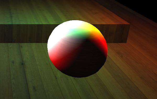
Fresnel gone wrong
A Fresnel Shader
So what does this look like in a shader? It’s actually very simple. First, you need to calculate the value of R. For this example, we’ll do that in the vertex shader:
vOUT vert(vIN v)
{
	vOUT o;
	o.pos = mul(UNITY_MATRIX_MVP, v.vertex);
	o.uv = v.texcoord;

	float3 posWorld = mul(_Object2World, v.vertex).xyz;
	float3 normWorld = normalize(mul(float3x3(_Object2World), v.normal));

	float3 I = normalize(posWorld - _WorldSpaceCameraPos.xyz);
	o.R = _Bias + _Scale * pow(1.0 + dot(I, normWorld), _Power);

	return o;
}
There isn’t too much to say about this, since it’s pretty much the equation above verbatim. One handy tip though: I’ve found that I’ve been perfectly happy with the results I get if I omit the bias parameter entirely, and doing so makes it more difficult to produce wonky results.
Once you have the R value calculated, the rest of the implementation is just a lerp in the fragment shader:
float4 frag(vOUT i) :  COLOR
{
	float4 col = tex2D(_MainTex, i.uv.xy * _MainTex_ST.xy + _MainTex_ST.zw);
	return lerp(col,_Color, i.R);
}
If you’re not a Unity programmer, ignore all the _MainTex_ST stuff, that’s just a unity specific bit of code to handle tiling textures across an object.
Otherwise, all that’s new here is the lerp function. In this example, rather than reflecting anything, our Fresnel Rim is just a single color (_Color), but the principle is the same. If you wanted to turn the rim into a reflection, you’d simply replace the _Color variable with a color sampled from a cube map, or taken from a camera, or however else you want to pass in a reflection.
Otherwise though, this is all there is to it to write a simple Fresnel shader, so go forth and make all of your objects more believable! And feel free to download the Fresnel Shader Pack that I’ve posted in the graphics section of this site to see some examples of more complicated Fresnel effects.
If you’ve spotted an error on here, or have anything to add, feel free to send me a message on twitter. Happy shading!


 被折叠的 条评论
为什么被折叠?
被折叠的 条评论
为什么被折叠?
 到【灌水乐园】发言


