


Programmable Materials, Effects, Geometry, and Texture data
可编程材质、效果、几何图形和纹理数据
While the built-in materials of Qt Quick 3D, DefaultMaterial and PrincipledMaterial, allow a wide degree of customization via their properties, they do not provide programmability on the vertex and fragment shader level. To allow that, the CustomMaterial type is provided.
虽然Qt Quick 3D、DefaultMaterial和PrincipledMaterial的内置材质允许通过其属性进行广泛的自定义,但它们在顶点和碎片着色器级别上不提供可编程性。为此,提供了CustomMaterial类型。
| A model with PrincipledMaterial 具有PrincipledMaterial的模型 | With a CustomMaterial transforming the vertices 使用CustomMaterial变换顶点 |
|---|---|
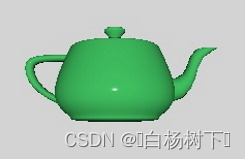 |  |
Post-processing effects, where one or more passes of processing on the color buffer are performed, optionally taking the depth buffer into account, before the View3D's output is passed on to Qt Quick, also exist in two varieties:
在View3D的输出传递给Qt Quick之前,对颜色缓冲区执行一次或多次处理(可选地考虑深度缓冲区)的后处理效果也有两种:
- built-in post-processing steps that can be configured via ExtendedSceneEnvironment, such as glow/bloom, depth of field, vignette, lens flare,
- 可通过ExtendedScenneEnvironment配置的内置后处理步骤,如光晕、景深、渐晕、镜头光斑,
customeffects implemented by the application in form of fragment shader code and a specification of the processing passes in an Effect object.- 由应用程序以片段着色器代码的形式实现的自定义效果以及Effect对象中处理过程的规范。
In practice there is a third category of post-processing effects: 2D effects implemented via Qt Quick, operating on the output of the View3D item without any involvement from the 3D renderer. For example, to apply a blur to a View3D item, the simplest approach is to use Qt Quick's existing facilities, such as MultiEffect. The 3D post-processing system becomes beneficial for complex effects that involve 3D scene concepts such as the depth buffer or the screen texture, or need to deal with HDR tonemapping or need multiple passes with intermediate buffers, etc. Simple 2D effects that do not require any insight into the 3D scene and renderer can always be implemented with ShaderEffect or MultiEffect instead.
在实践中,有第三类后处理效果:通过Qt Quick实现的2D效果,在不涉及3D渲染器的情况下对View3D项目的输出进行操作。例如,要将模糊应用于View3D项目,最简单的方法是使用Qt Quick的现有设施,如MultiEffect。3D后处理系统对于涉及3D场景概念(例如深度缓冲区或屏幕纹理)、或者需要处理HDR色调映射、或者需要具有中间缓冲区的多次通过等的复杂效果变得有益。不需要深入了解3D场景和渲染器的简单2D效果总是可以使用ShaderEffect或MultiEffect来实现。
| Scene without effect 没有效果的场景 | The same scene with a custom post-processing effect applied 应用了自定义后处理效果的同一场景 |
|---|---|
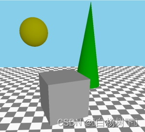 | 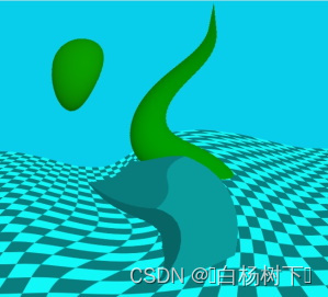 |
In addition to programmable materials and post-processing, there are two types of data that is normally provided in form of files (.mesh files or images such as .png):
除了可编程材料和后处理外,还有两种类型的数据通常以文件的形式提供(.mesh文件或.png等图像):
- vertex data, including the geometry for the mesh to be rendered, texture coordinates, normals, colors, and other data,
- 顶点数据,包括要渲染的网格的几何体、纹理坐标、法线、颜色和其他数据,
- the content for textures that are then used as texture maps for the rendered objects, or used with skybox or image based lighting.
- 纹理的内容,然后用作渲染对象的纹理贴图,或与skybox或基于图像的照明一起使用。
If they so wish, applications can provide such data from C++ in form of a QByteArray. Such data can also be changed over time, allowing to procedurally generate and later alter the data for a Model or Texture.
如果他们愿意,应用程序可以以QByteArray的形式从C++提供这样的数据。这样的数据也可以随着时间的推移而更改,从而可以按程序生成并稍后更改模型或纹理的数据。
| A grid, rendered by specifying vertex data dynamically from C++ 一个网格,通过从C++动态指定顶点数据来渲染 | A cube textured with image data generated from C++ 用C++生成的图像数据进行纹理处理的立方体 |
|---|---|
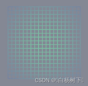 | 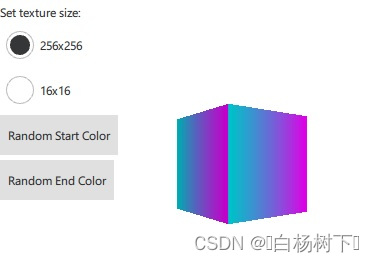 |
These four approaches to customizing and making materials, effects, geometry, and textures dynamic enable the programmability of shading and procedural generation of the data the shaders get as their input. The following sections provide an overview of these features. The full reference is available in the documentation pages for the respective types:
这四种自定义和使材质、效果、几何体和纹理动态的方法可以实现着色的可编程性,以及着色器作为其输入获得的数据的程序生成。以下各节概述了这些功能。文档页面中提供了相应类型的完整参考:
| Feature 特性 | Reference Documentation 参考文档 | Relevant Examples 关联示例 |
|---|---|---|
| Custom materials 自定义材质 | CustomMaterial | Qt Quick 3D - Custom Shaders Example, Qt Quick 3D - Custom Materials Example |
| Custom post-processing effects 自定义后处理效果 | Effect | Qt Quick 3D - Custom Effect Example |
| Custom geometry 自定义几何图形 | QQuick3DGeometry, Model::geometry | Qt Quick 3D - Custom Geometry Example |
| Custom texture data 自定义纹理数据 | QQuick3DTextureData, Texture::textureData | Qt Quick 3D - Procedural Texture Example |
Programmability for Materials
材质的可编程性
Let's have a scene with a cube, and start with a default PrincipledMaterial and CustomMaterial:
让我们有一个带有立方体的场景,并从默认的PrincipledMaterial和CustomMaterial开始:
| PrincipledMaterial | CustomMaterial |
|---|---|
import QtQuick import QtQuick3D Item { View3D { anchors.fill: parent environment: SceneEnvironment { backgroundMode: SceneEnvironment.Color clearColor: "black" } PerspectiveCamera { z: 600 } DirectionalLight { } Model { source: "#Cube" scale: Qt.vector3d(2, 2, 2) eulerRotation.x: 30 materials: PrincipledMaterial { } } } } | import QtQuick import QtQuick3D Item { View3D { anchors.fill: parent environment: SceneEnvironment { backgroundMode: SceneEnvironment.Color clearColor: "black" } PerspectiveCamera { z: 600 } DirectionalLight { } Model { source: "#Cube" scale: Qt.vector3d(2, 2, 2) eulerRotation.x: 30 materials: CustomMaterial { } } } } |
These both lead to the exact same result, because a CustomMaterial is effectively a PrincipledMaterial, when no vertex or fragment shader code is added to it.
这两者都会导致完全相同的结果,因为当没有向CustomMaterial添加顶点或片段着色器代码时,它实际上是PrincipledMaterial。
Note: Properties, such as, baseColor, metalness, baseColorMap, and many others, have no equivalent properties in the CustomMaterial QML type. This is by design: customizing the material is done via shader code, not by merely providing a few fixed values.
注意:属性,如baseColor、metalness、baseColorMap和许多其他属性,在CustomMaterial QML类型中没有等效的属性。这是经过设计的:自定义材质是通过着色器代码完成的,而不仅仅是提供几个固定值。
Our first vertex shader
我们的第一个顶点着色器
Let's add a custom vertex shader snippet. This is done by referencing a file in the vertexShader property. The approach will be the same for fragment shaders. These references work like Image.source or ShaderEffect.vertexShader: they are local or qrc URLs, and a relative path is treated relative to the .qml file's location. The common approach is therefore to place the .vert and .frag files into the Qt resource system (qt_add_resources when using CMake) and reference them using a relative path.
让我们添加一个自定义顶点着色器片段。这是通过引用vertexShader属性中的文件来完成的。该方法与片段着色器相同。这些引用的工作方式与Image.source或ShaderEffect.vertexShader类似:它们是本地或qrc URL,相对路径是相对于.qml文件的位置处理的。因此,常见的方法是将.vert和.frag文件放入Qt资源系统(使用CMake时为qt_add_resources)中,并使用相对路径引用它们。
In Qt 6.0 inline shader strings are no longer supported, neither in Qt Quick nor in Qt Quick 3D. (make note of the fact that these properties are URLs, not strings) However, due to their intrinsically dynamic nature, custom materials and post-processing effects in Qt Quick 3D still provide shader snippets in source form in the referenced files. This is a difference to ShaderEffect where the shaders are complete on their own, with no further amending by the engine, and so are expected to be provided as pre-conditioned .qsb shader packs.
在Qt 6.0中,Qt Quick和Qt Quick 3D都不再支持内联着色器字符串。(请注意,这些属性是URL,而不是字符串)但是,由于其固有的动态特性,Qt Quick 3D中的自定义材质和后处理效果仍然在引用文件中以源形式提供着色器片段。这与ShaderEffect的不同之处在于,着色器是独立完成的,引擎无需进一步修改,因此应作为预处理的.qsb着色器包提供。
Note: In Qt Quick 3D URLs can only refer to local resources. Schemes for remote content are not supported.
注意:在Qt Quick 3D中,URL只能引用本地资源。不支持远程内容的方案。
Note: The shading language used is Vulkan-compatible GLSL. The
.vertand.fragfiles are not complete shaders on their own, hence being often calledsnippets. That is why there are no uniform blocks, input and output variables, or sampler uniforms provided directly by these snippets. Rather, the Qt Quick 3D engine will amend them as appropriate.注:使用的着色语言是Vulkan兼容的GLSL。.vert和.frag文件本身不是完整的着色器,因此通常称为片段。这就是为什么这些片段没有直接提供统一的块、输入和输出变量或采样器统一。相反,Qt Quick 3D引擎将酌情对其进行修改。
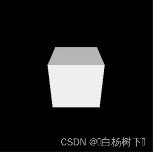
| Change in main.qml, material.vert main.qml、material.vert的变化 | Result 结果 |
|---|---|
materials: CustomMaterial {
    vertexShader: "material.vert"
}
void MAIN()
{
} |  |
A custom vertex or fragment shader snippet is expected to provide one or more functions with pre-defined names, such as MAIN, DIRECTIONAL_LIGHT, POINT_LIGHT, SPOT_LIGHT, AMBIENT_LIGHT, SPECULAR_LIGHT. For now let's focus on MAIN.
自定义顶点或片段着色器片段预计将提供一个或多个具有预定义名称的函数,例如MAIN、DIRECTIONAL_LIGHT、POINT_LIGHT、SPOT_LIGHT、AMBIENT_LIGHT和SPECULAR_LIGHT。现在让我们专注于MAIN。
As shown here, the end result with an empty MAIN() is exactly the same as before.
如图所示,MAIN()为空的最终结果与之前完全相同。
Before making it more interesting, let's look at an overview of the most commonly used special keywords in custom vertex shader snippets. This is not the full list. For a full reference, check the CustomMaterial page.
在让它变得更有趣之前,让我们先来看看自定义顶点着色器片段中最常用的特殊关键字的概述。这不是完整的列表。有关完整参考,请查看CustomMaterial页面。
| Keyword 关键字 | Type 类型 | Description 描述 |
|---|---|---|
| MAIN | void MAIN() is the entry point. This function must always be present in a custom vertex shader snippet, there is no point in providing one otherwise. void MAIN()是入口点。该函数必须始终存在于自定义顶点着色器片段中,否则提供该函数毫无意义。 | |
| VERTEX | vec3 | The vertex position the shader receives as input. A common use case for vertex shaders in custom materials is to change (displace) the x, y, or z values of this vector, by simply assigning a value to the whole vector, or some of its components. 着色器接收作为输入的顶点位置。自定义材质中顶点着色器的一个常见用例是通过简单地将值指定给整个向量或其某些组件来更改(置换)该向量的x、y或z值。 |
| NORMAL | vec3 | The vertex normal from the input mesh data, or all zeroes if there were no normals provided. As with VERTEX, the shader is free to alter the value as it sees fit. The altered value is then used by the rest of the pipeline, including the lighting calculations in the fragment stage. 来自输入网格数据的顶点法线,如果没有提供法线,则为全零。与VERTEX一样,着色器可以自由更改其认为合适的值。更改后的值随后被管道的其余部分使用,包括片段阶段中的照明计算。 |
| UV0 | vec2 | The first set of texture coordinates from the input mesh data, or all zeroes if there were no UV values provided. As with VERTEX and NORMAL, the value can altered. 输入网格数据中的第一组纹理坐标,如果没有提供UV值,则全部为零。与VERTEX和NORMAL一样,该值可以更改。 |
| MODELVIEWPROJECTION_MATRIX | mat4 | The model-view-projection matrix. To unify the behavior regardless of which graphics API rendering happens with, all vertex data and transformation matrices follow OpenGL conventions on this level. (Y axis pointing up, OpenGL-compatible projection matrix) Read only. 模型-视图-投影矩阵。为了统一行为,无论API渲染使用哪种图形,所有顶点数据和变换矩阵都遵循此级别的OpenGL约定。(Y轴指向上,OpenGL兼容投影矩阵)只读。 |
| MODEL_MATRIX | mat4 | The model (world) matrix. Read only. 模型(世界)矩阵。只读。 |
| NORMAL_MATRIX | mat3 | The transposed inverse of the top-left 3x3 slice of the model matrix. Read only. 模型矩阵左上角3x3切片的转置逆。只读。 |
| CAMERA_POSITION | vec3 | The camera position in world space. In the examples on this page this is 摄影机在世界空间中的位置。在本页的示例中,这是(0,0,600)。只读。 |
| CAMERA_DIRECTION | vec3 | The camera direction vector. In the examples on this page this is 摄影机方向矢量。在本页的示例中,这是(0,0,-1)。只读。 |
| CAMERA_PROPERTIES | vec2 | The near and far clip values of the camera. In the examples on this page this is 摄影机的近片段值和远片段值。在本页的示例中,这是(100000)。只读。 |
| POINT_SIZE | float | Relevant only when rendering with a topology of points, for example because the custom geometry provides such a geometry for the mesh. Writing to this value is equivalent to setting pointSize on a PrincipledMaterial. 仅在使用点拓扑进行渲染时相关,例如,因为自定义几何体为网格提供了这样的几何体。写入该值相当于在PrincipledMaterial上设置pointSize。 |
| POSITION | vec4 | Like 像gl_Position。如果不存在,则会使用MODELVIEW PROJECTION_MATRIX和VERTEX自动生成默认赋值语句。这就是为什么空的MAIN()是有效的,并且在大多数情况下不需要为它分配自定义值。 |
Let's make a custom material that displaces the vertices according to some pattern. To make it more interesting, have some animated QML properties, the values of which end up being exposed as uniforms in the shader code. (to be precise, most properties are going to be mapped to members in a uniform block, backed by a uniform buffer at run time, but Qt Quick 3D conveniently makes such details transparent to the custom material author)
让我们制作一种自定义材质,根据某种模式置换顶点。为了使其更有趣,请使用一些已设置动画的QML属性,这些属性的值最终在着色器代码中显示为uniforms。(准确地说,大多数属性将映射到uniform块中的成员,在运行时由uniform缓冲区支持,但Qt Quick 3D方便地使这些细节对自定义材质作者透明)
| Change in main.qml, material.vert main.qml、material.vert的变化 | Result 结果 |
|---|---|
materials: CustomMaterial {
   vertexShader: "material.vert"
   property real uAmplitude: 0
   NumberAnimation on uAmplitude {
       from: 0; to: 100; duration: 5000; loops: -1
   }
   property real uTime: 0
   NumberAnimation on uTime {
       from: 0; to: 100; duration: 10000; loops: -1
   }
}
void MAIN()
{
VERTEX.x += sin(uTime + VERTEX.y) * uAmplitude;
} | https://doc-snapshots.qt.io/qt6-dev/videos/quick3d-custom-cube2-anim.mp4 |
Uniforms from QML properties
来自QML属性的Uniforms
Custom properties in the CustomMaterial object get mapped to uniforms. In the above example this includes uAmplitude and uTime. Any time the values change, the updated value will become visible in the shader. This concept may already be familiar from ShaderEffect.
CustomMaterial对象中的自定义属性将映射到uniforms。在上面的示例中,这包括uAmplitude和uTime。每当值发生更改时,更新后的值都将在着色器中可见。这个概念在ShaderEffect中可能已经很熟悉了。
The name of the QML property and the GLSL variable must match. There is no separate declaration in the shader code for the individual uniforms. Rather, the QML property name can be used as-is. This is why the example above can just reference uTime and uAmplitude in the vertex shader snippet without any previous declaration for them.
QML属性的名称和GLSL变量的名称必须匹配。在着色器代码中没有针对各个uniforms的单独声明。相反,QML属性名称可以按原样使用。这就是为什么上面的示例可以在顶点着色器片段中仅引用uTime和uAmplitude,而不需要任何先前的声明。
The following table lists how the types are mapped:
下表列出了类型的映射方式:
| QML Type | Shader Type | Notes |
|---|---|---|
| real, int, bool | float, int, bool | |
| color | vec4 | sRGB to linear conversion is performed implicitly sRGB到线性的转换是隐式执行的 |
| vector2d | vec2 | |
| vector3d | vec3 | |
| vector4d | vec4 | |
| matrix4x4 | mat4 | |
| quaternion | vec4 | scalar value is
|
| rect | vec4 | |
| point, size | vec2 | |
| TextureInput | sampler2D |
Improving the example
改进示例
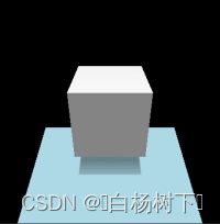
Before moving further, let's make the example somewhat better looking. By adding a rotated rectangle mesh and making the DirectionalLight cast shadows, we can verify that the alteration to the cube's vertices is correctly reflected in all rendering passes, including shadow maps. To get a visible shadow, the light is now placed a bit higher on the Y axis, and a rotation is applied to have it pointing partly downwards. (this being a directional light, the rotation matters)
在进一步讨论之前,让我们让这个例子看起来更好看一些。通过添加旋转的矩形网格并使DirectionalLight投射阴影,我们可以验证立方体顶点的更改是否正确反映在所有渲染过程中,包括阴影贴图。为了获得可见的阴影,现在将灯光放置在Y轴上稍高的位置,并应用旋转使其部分指向下方。(这是一个定向光,旋转很重要)
| main.qml, material.vert | Result |
|---|---|
import QtQuick
import QtQuick3D
Item {
    View3D {
        anchors.fill: parent
        environment: SceneEnvironment { backgroundMode: SceneEnvironment.Color; clearColor: "black" }
        PerspectiveCamera { z: 600 }
        DirectionalLight {
            y: 200
            eulerRotation.x: -45
            castsShadow: true
        }
        Model {
            source: "#Rectangle"
            y: -250
            scale: Qt.vector3d(5, 5, 5)
            eulerRotation.x: -45
            materials: PrincipledMaterial { baseColor: "lightBlue" }
        }
        Model {
            source: "#Cube"
            scale: Qt.vector3d(2, 2, 2)
            eulerRotation.x: 30
            materials: CustomMaterial {
                vertexShader: "material.vert"
                property real uAmplitude: 0
                NumberAnimation on uAmplitude {
                    from: 0; to: 100; duration: 5000; loops: -1
                }
                property real uTime: 0
                NumberAnimation on uTime {
                    from: 0; to: 100; duration: 10000; loops: -1
                }
            }
        }
    }
}
void MAIN()
{
VERTEX.x += sin(uTime + VERTEX.y) * uAmplitude;
} | https://doc-snapshots.qt.io/qt6-dev/videos/quick3d-custom-cube3-anim.mp4 |
Adding a fragment shader
添加片段着色器
Many custom materials will want to have a fragment shader as well. In fact, many will want only a fragment shader. If there is no extra data to be passed from the vertex to fragment stage, and the default vertex transformation is sufficient, setting the vertexShader property can be left out from the CustomMaterial.
许多自定义材质也希望具有片段着色器。事实上,许多人只想要一个片段着色器。如果没有额外的数据要从顶点传递到片段阶段,并且默认的顶点变换已经足够,则可以在CustomMaterial中省略设置vertexShader属性。
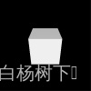
| Change in main.qml, material.frag | Result |
|---|---|
materials: CustomMaterial {
    fragmentShader: "material.frag"
}
void MAIN()
{
} |  |
Our first fragment shader contains an empty MAIN() function. This is no different than not specifying a fragment shader snippet at all: what we get looks like what we get with a default PrincipledMaterial.
我们的第一个片段着色器包含一个空的MAIN()函数。这与根本不指定片段着色器片段没有什么不同:我们得到的看起来就像我们使用默认Principled Material得到的一样。
Let's look at some of the commonly used keywords in fragment shaders. This is not the full list, refer to the CustomMaterial documentation for a complete reference. Many of these are read-write, meaning they have a default value, but the shader can, and often will want to, assign a different value to them.
让我们来看看片段着色器中一些常用的关键字。这不是完整的列表,请参阅CustomMaterial文档以获取完整的参考资料。其中许多都是读写的,这意味着它们有一个默认值,但着色器可以并且经常希望为它们指定不同的值。
As the names suggest, many of these map to similarly named PrincipledMaterial properties, with the same meaning and semantics, following the metallic-roughness material model. It is up the custom material implementation to decide how these values are calculated: for example, a value for BASE_COLOR can be hard coded in the shader, can be based on sampling a texture, or can be calculated based on QML properties exposed as uniforms or on interpolated data passed along from the vertex shader.
正如名称所示,其中许多映射到类似名称的PrincipledMaterial属性,具有相同的含义和语义,遵循金属粗糙度材料模型。由自定义材质实现来决定如何计算这些值:例如,BASE_COLOR的值可以在着色器中进行硬编码,可以基于纹理采样,也可以基于作为uniforms显示的QML特性或顶点着色器传递的插值数据进行计算。
| Keyword | Type | Description |
|---|---|---|
| BASE_COLOR | vec4 | The base color and alpha value. Corresponds to PrincipledMaterial::baseColor. The final alpha value of the fragment is the model opacity multiplied by the base color alpha. The default value is 基本颜色和alpha值。对应于Principled Material::baseColor。片段的最终alpha值是模型不透明度乘以基础颜色alpha。默认值为(1.0、1.0、1.0和1.0)。 |
| EMISSIVE_COLOR | vec3 | The color of self-illumination. Corresponds to PrincipledMaterial::emissiveFactor. The default value is |
| METALNESS | float | Metalness value in range 0-1. Default to 0, which means the material is dielectric (non-metallic). Metaness值在0-1范围内。默认为0,这意味着材料是电介质(非金属)。 |
| ROUGHNESS | float | Roughness value in range 0-1. The default value is 0. Larger values soften specular highlights and blur reflections. 粗糙度值在0-1范围内。默认值为0。较大的值会软化镜面反射高光和模糊反射。 |
| SPECULAR_AMOUNT | float | The strength of specularity in range 0-1. The default value is 范围为0-1的镜面反射强度。默认值为0.5。对于金属度设置为1的金属对象,此值将不起作用。当SPECULAR_AMOUNT和METALNESS的值都大于0但小于1时,结果是两个材质模型之间的混合。 |
| NORMAL | vec3 | The interpolated normal in world space, adjusted for double-sidedness when face culling is disabled. Read only. 世界空间中的插值法线,在禁用面剔除时为双面性进行调整。只读。 |
| UV0 | vec2 | The interpolated texture coordinates. Read only. 插值的纹理坐标。只读。 |
| VAR_WORLD_POSITION | vec3 | Interpolated vertex position in world space. Read only. 世界空间中的插值顶点位置。只读。 |
Let's make the cube's base color red:
让我们将立方体的基本颜色设为红色:
| Change in main.qml, material.frag | Result |
|---|---|
materials: CustomMaterial {
    fragmentShader: "material.frag"
}
void MAIN()
{
BASE_COLOR = vec4(1.0, 0.0, 0.0, 1.0);
} | 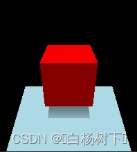 |
Now strengthen the level of self-illumination a bit:
现在稍微加强一下自我启发的水平:
| Change in main.qml, material.frag | Result |
|---|---|
materials: CustomMaterial {
    fragmentShader: "material.frag"
}
void MAIN()
{
BASE_COLOR = vec4(1.0, 0.0, 0.0, 1.0);
EMISSIVE_COLOR = vec3(0.4);
} | 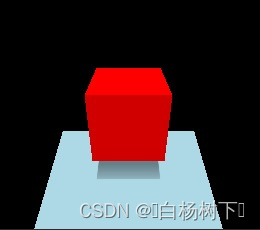 |
Instead of having values hardcoded in the shader, we could also use QML properties exposed as uniforms, even animated ones:
我们也可以使用以uniforms形式公开的QML属性,甚至是动画属性,而不是在着色器中硬编码值:
| Change in main.qml, material.frag | Result |
|---|---|
materials: CustomMaterial {
    fragmentShader: "material.frag"
    property color baseColor: "black"
    ColorAnimation on baseColor {
        from: "black"; to: "purple"; duration: 5000; loops: -1
    }
}
void MAIN()
{
BASE_COLOR = vec4(baseColor.rgb, 1.0);
EMISSIVE_COLOR = vec3(0.4);
} | https://doc-snapshots.qt.io/qt6-dev/videos/quick3d-custom-cube7-anim.mp4 |
Let's do something less trivial, something that is not implementable with a PrincipledMaterial and its standard, built-in properties. The following material visualizes the texture UV coordinates of the cube mesh. U runs 0 to 1, so from black to red, while V is also 0 to 1, black to green.
让我们做一些不那么琐碎的事情,一些Principled Material及其标准内置属性无法实现的事情。以下材质可可视化立方体网格的纹理UV坐标。U从0到1,所以从黑色到红色,而V也是从0到1,从黑色到绿色。
| Change in main.qml, material.frag | Result |
|---|---|
materials: CustomMaterial {
    fragmentShader: "material.frag"
}
void MAIN()
{
BASE_COLOR = vec4(UV0, 0.0, 1.0);
} | 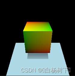 |
While we are at it, why not visualize normals as well, this time on a sphere. Like with UVs, if a custom vertex shader snippet were to alter the value of NORMAL, the interpolated per-fragment value in the fragment shader, also exposed under the name NORMAL, would reflect those adjustments.
当我们在做的时候,为什么不把法线也可视化呢,这次是在球体上。与UV类似,如果自定义顶点着色器片段要更改NORMAL的值,则片段着色器中插值的每个片段值(也以名称NORMAL暴露)将反映这些调整。
| Change in main.qml, material.frag | Result |
|---|---|
Model {
    source: "#Sphere"
    scale: Qt.vector3d(2, 2, 2)
    materials: CustomMaterial {
        fragmentShader: "material.frag"
    }
}
void MAIN()
{
BASE_COLOR = vec4(NORMAL, 1.0);
} | 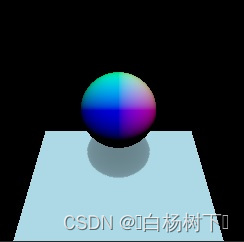 |
Colors
颜色
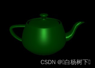
Let's switch over to a teapot model for a moment, make the material a blend of metallic and dielectric, and try to set a green base color for it. The green QColor value maps to (0, 128, 0), based on which our first attempt could be:
让我们暂时切换到茶壶模型,使材料成为金属和电介质的混合物,并尝试为其设置绿色基础颜色。绿色QColor值映射到(0,128,0),基于此,我们的第一次尝试可能是:
| main.qml, material.frag |
|---|
import QtQuick
import QtQuick3D
Item {
    View3D {
        anchors.fill: parent
        environment: SceneEnvironment { backgroundMode: SceneEnvironment.Color; clearColor: "black" }
        PerspectiveCamera { z: 600 }
        DirectionalLight { }
        Model {
            source: "teapot.mesh"
            scale: Qt.vector3d(60, 60, 60)
            eulerRotation.x: 30
            materials: CustomMaterial {
                fragmentShader: "material.frag"
            }
        }
    }
}
void MAIN()
{
BASE_COLOR = vec4(0.0, 0.5, 0.0, 1.0);
METALNESS = 0.6;
SPECULAR_AMOUNT = 0.4;
ROUGHNESS = 0.4;
} |

This does not look entirely right. Compare with the second approach:
这看起来并不完全正确。与第二种方法相比:
| Change in main.qml, material.frag main.qml、material.frag的变化 | Result 结果 |
|---|---|
materials: CustomMaterial {
    fragmentShader: "material.frag"
    property color uColor: "green"
}
void MAIN()
{
BASE_COLOR = vec4(uColor.rgb, 1.0);
METALNESS = 0.6;
SPECULAR_AMOUNT = 0.4;
ROUGHNESS = 0.4;
} | 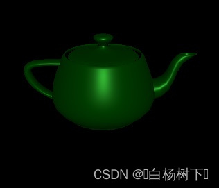 |
Switching to a PrincipledMaterial, we can confirm that setting the PrincipledMaterial::baseColor to "green" and following the metalness and other properties, the result is identical to our second approach:
切换到Principled Material,我们可以确认,将PrincipledMaterial::baseColor设置为“绿色”,并遵循金属性和其他特性,结果与我们的第二种方法相同:
| Change in main.qml main.qml的变化 | Result 结果 |
|---|---|
materials: PrincipledMaterial {
    baseColor: "green"
    metalness: 0.6
    specularAmount: 0.4
    roughness: 0.4
} |  |
If the type of the uColor property was changed to vector4d, or any type other than color, the results would suddenly change and become identical to our first approach.
如果uColor属性的类型更改为vector4d,或颜色以外的任何类型,结果将突然发生变化,并与我们的第一种方法相同。
Why is this?
为什么会这样?
The answer lies in the sRGB to linear conversion that is performed implicitly for color properties of DefaultMaterial, PrincipledMaterial, and also for custom properties with a color type in a CustomMaterial. Such conversion is not performed for any other value, so if the shader hardcodes a color value, or bases it on a QML property with a type different from color, it will be up to the shader to perform linearization in case the source value was in sRGB color space. Converting to linear is important since Qt Quick 3D performs tonemapping on the results of fragment shading, and that process assumes values in the sRGB space as its input.
答案在于sRGB到线性转换,该转换是为DefaultMaterial、PrincipledMaterial的颜色属性以及CustomMaterial中具有颜色类型的自定义属性隐式执行的。这种转换不会对任何其他值执行,因此,如果着色器对颜色值进行硬编码,或将其基于与颜色不同类型的QML属性,则在源值位于sRGB颜色空间的情况下,将由着色器执行线性化。转换为线性很重要,因为Qt Quick 3D对片段着色的结果执行色调映射,并且该过程假设sRGB空间中的值作为其输入。
The built-in QColor constants, such as, "green", are all given in sRGB space. Therefore, just assigning vec4(0.0, 0.5, 0.0, 1.0) to BASE_COLOR in the first attempt is insufficient if we wanted a result that matches an RGB value (0, 128, 0) in the sRGB space. See the BASE_COLOR documentation in CustomMaterial for a formula for linearizing such color values. The same applies to color values retrieved by sampling textures: if the source image data is not in the sRGB color space, a conversion is needed (unless tonemapping is disabled).
内置的QColor常量,如“green”,都是在sRGB空间中给出的。因此,如果我们想要与sRGB空间中的RGB值(0128,0)匹配的结果,那么在第一次尝试中仅将vec4(0.0,0.5,0.0,1.0)指定给BASE_COLOR是不够的。有关线性化此类颜色值的公式,请参阅CustomMaterial中的BASE_COLOR文档。这同样适用于通过采样纹理检索的颜色值:如果源图像数据不在sRGB颜色空间中,则需要进行转换(除非禁用色调映射)。
Blending
混合
Just writing a value less than 1.0 to BASE_COLOR.a is not sufficient if the expectation is to get alpha blending. Such materials will very often change the values of sourceBlend and destinationBlend properties to get the desired results.
如果期望得到alpha混合,那么仅仅将小于1.0的值写入BASE_COLOR.a是不够的。此类材质通常会更改sourceBlend和destinationBlend属性的值,以获得所需的结果。
Also keep in mind that the combined alpha value is the Node opacity multiplied by the material alpha.
还要记住,组合的alpha值是节点不透明度乘以材质alpha。
To visualize, let's use a shader that assigns red with alpha 0.5 to BASE_COLOR:
要进行可视化,让我们使用一个着色器,将alpha为0.5的红色指定给BASE_COLOR:
| main.qml, material.frag | Result |
|---|---|
import QtQuick
import QtQuick3D
Item {
    View3D {
        anchors.fill: parent
        environment: SceneEnvironment {
            backgroundMode: SceneEnvironment.Color
            clearColor: "white"
        }
        PerspectiveCamera {
            id: camera
            z: 600
        }
        DirectionalLight { }
        Model {
            source: "#Cube"
            x: -150
            eulerRotation.x: 60
            eulerRotation.y: 20
            materials: CustomMaterial {
                fragmentShader: "material.frag"
            }
        }
        Model {
            source: "#Cube"
            eulerRotation.x: 60
            eulerRotation.y: 20
            materials: CustomMaterial {
                sourceBlend: CustomMaterial.SrcAlpha
                destinationBlend: CustomMaterial.OneMinusSrcAlpha
                fragmentShader: "material.frag"
            }
        }
        Model {
            source: "#Cube"
            x: 150
            eulerRotation.x: 60
            eulerRotation.y: 20
            materials: CustomMaterial {
                sourceBlend: CustomMaterial.SrcAlpha
                destinationBlend: CustomMaterial.OneMinusSrcAlpha
                fragmentShader: "material.frag"
            }
            opacity: 0.5
        }
    }
}
void MAIN()
{
BASE_COLOR = vec4(1.0, 0.0, 0.0, 0.5);
} | 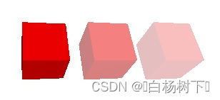 |
The first cube is writing 0.5 to the alpha value of the color but it does not bring visible results since alpha blending is not enabled. The second cube enables simple alpha blending via the CustomMaterial properties. The third one also assigns an opacity of 0.5 to the Model, which means that the effective opacity is 0.25.
第一个立方体将0.5写入颜色的alpha值,但由于未启用alpha混合,因此不会带来可见的结果。第二个立方体通过CustomMaterial属性实现简单的alpha混合。第三个还为“模型”指定0.5的不透明度,这意味着有效不透明度为0.25。
Passing data between the vertex and fragment shader
在顶点着色器和片段着色器之间传递数据
Calculating a value per vertex (for example, assuming a single triangle, for the 3 corners of the triangle), and then passing it on to the fragment stage, where for each fragment (for example, every fragment covered by the rasterized triangle) an interpolated value is made accessible. In custom material shader snippets this is made possible by the VARYING keyword. This provides a syntax similar to GLSL 120 and GLSL ES 100, but will work regardless of the graphics API used at run time. The engine will take care of rewriting the varying declaration as appropriate.
计算每个顶点的值(例如,假设三角形的3个角为单个三角形),然后将其传递到片段阶段,在那里,对于每个片段(例如,光栅化三角形覆盖的每个片段),可以访问插值。在自定义材质着色器片段中,这是通过VARYING关键字实现的。这提供了类似于GLSL 120和GLSL ES 100的语法,但无论在运行时使用什么图形API,都可以工作。引擎将负责根据需要重写变化的声明。
Let's see how the classic texture sampling with UV coordinates would look like. Textures are going to be covered in an upcoming section, for now let's focus on how we get the UV coordinates that can be passed to the texture() function in the shader.
让我们看看使用UV坐标的经典纹理采样的外观。纹理将在下一节中介绍,现在让我们重点讨论如何获得可以传递给着色器中的texture()函数的UV坐标。
| main.qml, material.vert, material.frag |
|---|
import QtQuick
import QtQuick3D
Item {
    View3D {
        anchors.fill: parent
        environment: SceneEnvironment { backgroundMode: SceneEnvironment.Color; clearColor: "black" }
        PerspectiveCamera { z: 600 }
        DirectionalLight { }
        Model {
            source: "#Sphere"
            scale: Qt.vector3d(4, 4, 4)
            eulerRotation.x: 30
            materials: CustomMaterial {
                vertexShader: "material.vert"
                fragmentShader: "material.frag"
                property TextureInput someTextureMap: TextureInput {
                    texture: Texture {
                        source: "qt_logo_rect.png"
                    }
                }
            }
        }
    }
}
VARYING vec2 uv;
void MAIN()
{
uv = UV0;
} VARYING vec2 uv;
void MAIN()
{
BASE_COLOR = texture(someTextureMap, uv);
} |
| qt_logo_rect.png | Result |
|---|---|
 |  |
Note that VARYING declarations. The name and type must match, uv in the fragment shader will expose the interpolated UV coordinate for the current fragment.
请注意,VARYING声明。名称和类型必须匹配,片段着色器中的uv将显示当前片段的插值uv坐标。
Any other type of data can be passed on to the fragment stage in a similar manner. It is worth noting that in many cases setting up the material's own varyings is not necessary because there are builtins provided that cover many of typical needs. This includes making the (interpolated) normals, UVs, world position (VAR_WORLD_POSITION), or the vector pointing towards the camera (VIEW_VECTOR).
任何其他类型的数据都可以以类似的方式传递到片段阶段。值得注意的是,在许多情况下,没有必要设置材料自己的变量,因为提供了涵盖许多典型需求的内置组件。这包括制作(插值)法线、UV、世界位置(VAR_WORLD_POSITION)或指向摄影机的矢量(VIEW_VECTOR)。
The above example can in fact be simplified to the following as UV0 is automatically available in the fragment stage as well:
事实上,由于UV0在片段阶段也是自动可用的,因此上述示例可以简化为以下内容:
| Change in main.qml, material.frag main.qml、material.frag的变化 | Result 结果 |
|---|---|
materials: CustomMaterial {
    fragmentShader: "material.frag"
    property TextureInput someTextureMap: TextureInput {
        texture: Texture {
        source: "qt_logo_rect.png"
    }
}
void MAIN()
{
BASE_COLOR = texture(someTextureMap, UV0);
} |  |
To disable interpolation for a variable, use the flat keyword in both the vertex and fragment shader snippet. For example:
若要禁用变量的插值,请在顶点和片段着色器片段中同时使用flat关键字。例如
VARYING flat vec2 v;
Textures
纹理
A CustomMaterial has no built-in texture maps, meaning there is no equivalent of, for example, PrincipledMaterial::baseColorMap. This is because implementing the same is often trivial, while giving a lot more flexibility than what DefaultMaterial and PrincipledMaterial has built in. Besides simply sampling a texture, custom fragment shader snippets are free to combine and blend data from various sources when calculating the values they assign to BASE_COLOR, EMISSIVE_COLOR, ROUGHNESS, etc. They can base these calculations on data provided via QML properties, interpolated data sent on from the vertex stage, values retrieved from sampling textures, and on hardcoded values.
CustomMaterial没有内置纹理贴图,这意味着没有等效的纹理贴图,例如PrincipledMaterial::baseColorMap。这是因为实现同样的功能通常很简单,同时比DefaultMaterial和PrincipledMaterial内置的功能提供了更大的灵活性。除了简单地对纹理进行采样外,自定义片段着色器片段在计算分配给BASE_COLOR、EMISSIVE_COLOR、ROUGHNESS等的值时,还可以自由地组合和混合来自各种来源的数据。它们可以基于QML属性提供的数据、从顶点阶段发送的插值数据、从采样纹理检索到的值以及硬编码值来进行这些计算。
As the previous example shows, exposing a texture to the vertex, fragment, or both shaders is very similar to scalar and vector uniform values: a QML property with the type TextureInput will automatically get associated with a sampler2D in the shader code. As always, there is no need to declare this sampler in the shader code.
如前一个示例所示,将纹理暴露给顶点、片段或两个着色器与标量和向量uniform值非常相似:类型为TextureInput的QML属性将自动与着色器代码中的sampler2D关联。一如既往,不需要在着色器代码中声明此采样器。
A TextureInput references a Texture, with an additional enabled property. A Texture can source its data in three ways: from an image file, from a texture with live Qt Quick content, or can be provided from C++ via QQuick3DTextureData.
TextureInput引用具有附加启用特性的纹理。纹理可以通过三种方式获取数据:来自图像文件、来自具有实时Qt Quick内容的纹理,或者可以通过QQuick3DTextureData从C++提供。
Note: When it comes to Texture properties, the source, tiling, and filtering related ones are the only ones that are taken into account implicitly with custom materials, as the rest (such as, UV transformations) is up to the custom shaders to implement as they see fit.
注意:当涉及到纹理属性时,源、平铺和过滤相关的属性是自定义材质中唯一隐式考虑的属性,因为其他属性(如UV变换)取决于自定义着色器在其认为合适的情况下实现。
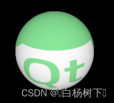
Let's see an example where a model, a sphere in this case, is textured using live Qt Quick content:
让我们看一个示例,其中使用实时Qt Quick内容对模型(本例中为球体)进行纹理处理:
| main.qml, material.frag |
|---|
import QtQuick
import QtQuick3D
Item {
    View3D {
        anchors.fill: parent
        environment: SceneEnvironment { backgroundMode: SceneEnvironment.Color; clearColor: "black" }
        PerspectiveCamera { z: 600 }
        DirectionalLight { }
        Model {
            source: "#Sphere"
            scale: Qt.vector3d(4, 4, 4)
            eulerRotation.x: 30
            materials: CustomMaterial {
                fragmentShader: "material.frag"
                property TextureInput someTextureMap: TextureInput {
                    texture: Texture {
                        sourceItem: Rectangle {
                            width: 512; height: 512
                            color: "red"
                            Rectangle {
                                width: 32; height: 32
                                anchors.horizontalCenter: parent.horizontalCenter
                                y: 150
                                color: "gray";
                                NumberAnimation on rotation { from: 0; to: 360; duration: 3000; loops: -1 }
                            }
                            Text {
                                anchors.centerIn: parent
                                text: "Texture Map"
                                font.pointSize: 16
                            }
                        }
                    }
                }
            }
        }
    }
}
void MAIN()
{
vec2 uv = vec2(UV0.x, 1.0 - UV0.y);
vec4 c = texture(someTextureMap, uv);
BASE_COLOR = c;
} |
https://doc-snapshots.qt.io/qt6-dev/videos/quick3d-custmat-tex1-anim.mp4
Here the 2D subtree (Rectangle with two children: another Rectangle and the Text) is rendered in to an 512x512 2D texture every time this mini-scene changes. The texture is then exposed to the custom material under the name of someTextureMap.
在这里,每当这个小场景发生变化时,2D子树(具有两个子项的矩形:另一个矩形和文本)都会渲染为512x512 2D纹理。然后,该纹理以someTextureMap的名称暴露给自定义材质。
Note the flipping of the V coordinate in the shader. As noted above, custom materials, where there is full programmability on shader level, do not offer the "fixed" features of Texture and PrincipledMaterial. This means that any transformations to the UV coordinates will need to be applied by the shader. Here we know that the texture is generated via Texture::sourceItem and so V needs to be flipped to get something that matches the UV set of the mesh we are using.
请注意着色器中V坐标的翻转。如上所述,在着色器级别上具有完全可编程性的自定义材质不提供“Texture”和“PrincipledMaterial”的“固定”功能。这意味着任何到UV坐标的变换都需要由着色器应用。在这里,我们知道纹理是通过Texture::sourceItem生成的,因此需要翻转V以获得与我们正在使用的网格的UV集匹配的东西。
What this example shows is possible to do with a PrincipledMaterial too. Let's make it more interesting by doing a simple emboss effect in addition:
这个例子显示的内容也可以用PrincipledMaterial来实现。让我们通过做一个简单的浮雕效果来增加趣味性:
| material.frag | Result |
|---|---|
void MAIN()
{
    vec2 uv = vec2(UV0.x, 1.0 - UV0.y);
    vec2 size = vec2(textureSize(someTextureMap, 0));
    vec2 d = vec2(1.0 / size.x, 1.0 / size.y);
    vec4 diff = texture(someTextureMap, uv + d) - texture(someTextureMap, uv - d);
    float c = (diff.x + diff.y + diff.z) + 0.5;
    BASE_COLOR = vec4(c, c, c, 1.0);
} | https://doc-snapshots.qt.io/qt6-dev/videos/quick3d-custmat-tex2-anim.mp4 |
With the features covered so far a wide range of possibilities are open for creating materials that shade the meshes in visually impressive ways. To finish the basic tour, let's look at an example that applies height and normal maps to a plane mesh. (a dedicated .mesh file is used here because the builtin #Rectangle does not have enough subdivisions) For better lighting results, we will use image based lighting with a 360 degree HDR image. The image is also set as the skybox to make it more clear what is happening.
到目前为止,已经涵盖了各种功能,可以创建以视觉上令人印象深刻的方式为网格着色的材质。要完成基本教程,让我们看一个将高度贴图和法线贴图应用于平面网格的示例。(此处使用了专用的.mesh文件,因为内置的#Rectangle没有足够的细分)为了获得更好的照明效果,我们将使用基于图像的照明和360度HDR图像。该图像也被设置为skybox,以使其更清楚地显示正在发生的事情。
First let's start with an empty CustomMaterial:
首先,让我们从一个空的CustomMaterial开始:
| main.qml | Result |
|---|---|
import QtQuick import QtQuick3D Item { View3D { anchors.fill: parent environment: SceneEnvironment { backgroundMode: SceneEnvironment.SkyBox lightProbe: Texture { source: "00489_OpenfootageNET_snowfield_low.hdr" } } PerspectiveCamera { z: 600 } Model { source: "plane.mesh" scale: Qt.vector3d(400, 400, 400) z: 400 y: -50 eulerRotation.x: -90 materials: CustomMaterial { } } } } | 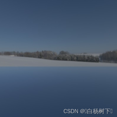 |
Now let's make some shaders that apply a height and normal map to the mesh:
现在,让我们制作一些着色器,将高度和法线贴图应用于网格:
| Height map | Normap map |
|---|---|
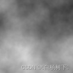 |  |
| material.vert, material.frag |
|---|
float getHeight(vec2 pos)
{
    return texture(heightMap, pos).r;
}

void MAIN()
{
    const float offset = 0.004;
    VERTEX.y += getHeight(UV0);
    TANGENT = normalize(vec3(0.0, getHeight(UV0 + vec2(0.0, offset)) - getHeight(UV0 + vec2(0.0, -offset)), offset * 2.0));
    BINORMAL = normalize(vec3(offset * 2.0, getHeight(UV0 + vec2(offset, 0.0)) - getHeight(UV0 + vec2(-offset, 0.0)), 0.0));
    NORMAL = cross(TANGENT, BINORMAL);
}
void MAIN()
{
vec3 normalValue = texture(normalMap, UV0).rgb;
normalValue.xy = normalValue.xy * 2.0 - 1.0;
normalValue.z = sqrt(max(0.0, 1.0 - dot(normalValue.xy, normalValue.xy)));
NORMAL = normalize(mix(NORMAL, TANGENT * normalValue.x + BINORMAL * normalValue.y + NORMAL * normalValue.z, 1.0));
} |
| Change in main.qml | Result |
|---|---|
materials: CustomMaterial {
    vertexShader: "material.vert"
    fragmentShader: "material.frag"
    property TextureInput normalMap: TextureInput {
        texture: Texture { source: "normalmap.jpg" }
    }
    property TextureInput heightMap: TextureInput {
        texture: Texture { source: "heightmap.png" }
    }
} | 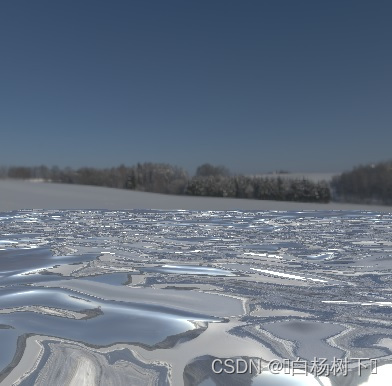 |
Note: The WasdController object can be immensely helpful during development and troubleshooting as it allows navigating and looking around in the scene with the keyboard and mouse in a familiar manner. Having a camera controlled by the WasdController is as simple as:
注意:WasdController对象在开发和故障排除过程中非常有用,因为它允许以熟悉的方式使用键盘和鼠标在场景中导航和环视。由WasdController控制相机非常简单:
import QtQuick3D.Helpers
View3D {
    PerspectiveCamera {
        id: camera
    }
    // ...
}
WasdController {
    controlledObject: camera
}
Depth and screen textures
深度和屏幕纹理
When a custom shader snippet uses the DEPTH_TEXTURE or SCREEN_TEXTURE keywords, it opts in to generating the corresponding textures in a separate render pass, which is not necessarily a cheap operation, but allows implementing a variety of techniques, such as refraction for glass-like materials.
当自定义着色器片段使用DEPTH_TEXTURE或SCREEN_TEXTURE关键字时,它会选择在单独的渲染过程中生成相应的纹理,这不一定是一种廉价的操作,但允许实现各种技术,例如类似玻璃的材质的折射。
DEPTH_TEXTURE is a sampler2D that allows sampling a texture with the contents of the depth buffer with all the opaque objects in the scene rendered. Similarly, SCREEN_TEXTURE is a sampler2D that allows sampling a texture containing the contents of the scene excluding any transparent materials or any materials also using the SCREEN_TEXTURE. The texture can be used for materials that require the contents of the framebuffer they are being rendered to. The SCREEN_TEXTURE texture uses the same clear mode as the View3D. The size of these textures matches the size of the View3D in pixels.
DEPTH_TEXTURE是一个sampler2D,它允许对具有深度缓冲区内容的纹理进行采样,同时渲染场景中的所有不透明对象。类似地,SCREEN_TEXTURE是一个sampler2D,它允许对包含场景内容的纹理进行采样,不包括任何透明材质或也使用SCREEN_TEXTURE的任何材质。该纹理可用于需要渲染到的帧缓冲区内容的材质。SCREEN_TEXTURE纹理使用与View3D相同的清除模式。这些纹理的大小与View3D的像素大小相匹配。
Let's have a simple demonstration by visualizing the depth buffer contents via DEPTH_TEXTURE. The camera's far clip value is reduced here from the default 10000 to 2000, in order to have a smaller range, and so have the visualized depth value differences more obvious. The result is a rectangle that happens to visualize the depth buffer for the scene over its surface.
让我们通过DEPTH_TEXTURE可视化深度缓冲区内容来进行一个简单的演示。相机的远片段值在这里从默认的10000减少到2000,以便具有更小的范围,从而使可视化的深度值差异更加明显。结果是一个矩形,正好将场景的深度缓冲区可视化到其曲面上。
| main.qml, material.frag | Result |
|---|---|
import QtQuick
import QtQuick3D
import QtQuick3D.Helpers
Rectangle {
    width: 400
    height: 400
    color: "black"
    View3D {
        anchors.fill: parent
        PerspectiveCamera {
            id: camera
            z: 600
            clipNear: 1
            clipFar: 2000
        }
        DirectionalLight { }
        Model {
            source: "#Cube"
            scale: Qt.vector3d(2, 2, 2)
            position: Qt.vector3d(150, 200, -1000)
            eulerRotation.x: 60
            eulerRotation.y: 20
            materials: PrincipledMaterial { }
        }
        Model {
            source: "#Cylinder"
            scale: Qt.vector3d(2, 2, 2)
            position: Qt.vector3d(400, 200, -1000)
            materials: PrincipledMaterial { }
            opacity: 0.3
        }
        Model {
            source: "#Sphere"
            scale: Qt.vector3d(2, 2, 2)
            position: Qt.vector3d(-150, 200, -600)
            materials: PrincipledMaterial { }
        }
        Model {
            source: "#Cone"
            scale: Qt.vector3d(2, 2, 2)
            position: Qt.vector3d(0, 400, -1200)
            materials: PrincipledMaterial { }
        }
        Model {
            source: "#Rectangle"
            scale: Qt.vector3d(3, 3, 3)
            y: -150
            materials: CustomMaterial {
                fragmentShader: "material.frag"
            }
        }
    }
    WasdController {
        controlledObject: camera
    }
}
void MAIN()
{
float zNear = CAMERA_PROPERTIES.x;
float zFar = CAMERA_PROPERTIES.y;
float zRange = zFar - zNear;
vec4 depthSample = texture(DEPTH_TEXTURE, vec2(UV0.x, 1.0 - UV0.y));
float zn = 2.0 * depthSample.r - 1.0;
float d = 2.0 * zNear * zFar / (zFar + zNear - zn * zRange);
d /= zFar;
BASE_COLOR = vec4(d, d, d, 1.0);
} | https://doc-snapshots.qt.io/qt6-dev/videos/quick3d-custom-depth-anim.mp4 |
Note how the cylinder is not present in DEPTH_TEXTURE due to its reliance on semi-transparency, which puts it into a different category than the other objects that are all opaque. These objects do not write into the depth buffer, although they do test against the depth values written by opaque objects, and rely on being rendered in back to front order. Hence they are not present in DEPTH_TEXTURE either.
请注意,由于圆柱体依赖于半透明性,因此圆柱体不存在于DEPTH_TEXTURE中,这使圆柱体与其他完全不透明的对象处于不同的类别中。这些对象不会写入深度缓冲区,尽管它们会根据不透明对象写入的深度值进行测试,并且依赖于按后到时前顺序进行渲染。因此,它们也不存在于DEPTH_TEXTURE中。
What happens if we switch the shader to sample SCREEN_TEXTURE instead?
如果我们将着色器切换到样例SCREEN_TEXTURE,会发生什么?
| material.frag | Result |
|---|---|
void MAIN()
{
    vec4 c = texture(SCREEN_TEXTURE, vec2(UV0.x, 1.0 - UV0.y));
    if (c.a == 0.0)
        c.rgb = vec3(0.2, 0.1, 0.3);
    BASE_COLOR = c;
} | 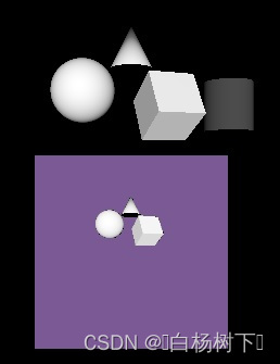 |
Here the rectangle is textured with SCREEN_TEXTURE, while replacing transparent pixels with purple.
此处,矩形使用SCREEN_TEXTURE进行纹理处理,同时用紫色替换透明像素。
Light processor functions
灯光处理器函数
An advanced feature of CustomMaterial is the ability to define functions in the fragment shader that reimplement the lighting equations that are used to calculate the fragment color. A light processor function, when present, is called once per each light in the scene, for each fragment. There is a dedicated function for different light types, as well as the ambient and specular contribution. When no corresponding light processor function is present, the standard calculations are used, just like a PrincipledMaterial would do. When a light processor is present, but the function body is empty, it means there will be no contribution from a given type of lights in the scene.
CustomMaterial的一个高级功能是能够在片段着色器中定义函数,这些函数可以重新实现用于计算片段颜色的照明方程。光处理器函数(如果存在)会为场景中的每个光、每个片段调用一次。有一个专门的功能用于不同的光类型,以及环境光和镜面反射的贡献。当不存在相应的光处理器功能时,将使用标准计算,就像PrincipledMaterial一样。当存在光处理器,但函数体为空时,这意味着场景中给定类型的光将没有贡献。
Refer to the CustomMaterial documentation for details on functions such as DIRECTIONAL_LIGHT, POINT_LIGHT, SPOT_LIGHT, AMBIENT_LIGHT, and SPECULAR_LIGHT.
有关DIRECTIONAL_LIGHT、POINT_LIGHT、SPOT_LIGHT、AMBIENT_LIGHT和SPECULAR_LIGHT等功能的详细信息,请参阅CustomMaterial文档。
Unshaded custom materials
未遮挡的自定义材质
There is another type of CustomMaterial: unshaded custom materials. All the example so far used shaded custom materials, with the shadingMode property left at its default CustomMaterial .Shaded value.
还有另一种类型的自定义材质:unshaded自定义材质。到目前为止,所有示例都使用shaded的自定义材质,shadingMode特性保留为其默认的“CustomMaterial.Shaded ”值。
What happens if we switch this property to CustomMaterial.Unshaded?
如果我们将此属性切换为CustomMaterial.Unshaded会发生什么?
First of all, keywords like BASE_COLOR, EMISSIVE_COLOR, METALNESS, etc. no longer have the desired effect. This is because an unshaded material, as the name suggests, does not automatically get amended with much of the standard shading code, thus ignoring lights, image based lighting, shadows, and ambient occlusion in the scene. Rather, an unshaded material gives full control to the shader via the FRAGCOLOR keyword. This is similar to gl_FragColor: the color assigned to FRAGCOLOR is the result and the final color of the fragment, without any further adjustments by Qt Quick 3D.
首先,像BASE_COLOR、EMISSIVE_COLOR、METALNESS等关键字不再具有所需的效果。这是因为顾名思义,未着色的材质不会自动使用大部分标准着色代码进行修改,从而忽略场景中的灯光、基于图像的照明、阴影和环境光遮挡。相反,未着色材质通过FRAGCOLOR关键字为着色器提供完全控制。这与gl_FragColor类似:分配给FRAGCOLOR的颜色是片段的结果和最终颜色,Qt Quick 3D无需进行任何进一步调整。
| main.qml, material.frag, material2.frag | Result |
|---|---|
import QtQuick
import QtQuick3D
Item {
    View3D {
        anchors.fill: parent
        environment: SceneEnvironment {
            backgroundMode: SceneEnvironment.Color
            clearColor: "black"
        }
        PerspectiveCamera { z: 600 }
        DirectionalLight { }
        Model {
            source: "#Cylinder"
            x: -100
            eulerRotation.x: 30
            materials: CustomMaterial {
                fragmentShader: "material.frag"
            }
        }
        Model {
            source: "#Cylinder"
            x: 100
            eulerRotation.x: 30
            materials: CustomMaterial {
                shadingMode: CustomMaterial.Unshaded
                fragmentShader: "material2.frag"
            }
        }
    }
}
void MAIN()
{
BASE_COLOR = vec4(1.0);
} void MAIN()
{
FRAGCOLOR = vec4(1.0);
} |  |
Notice how the right cylinder ignores the DirectionalLight in the scene. Its shading knows nothing about scene lighting, the final fragment color is all white.
请注意右侧圆柱体如何忽略场景中的DirectionalLight。它的着色对场景照明一无所知,最终片段的颜色都是白色。
The vertex shader in an unshaded material still has the typical inputs available: VERTEX, NORMAL, MODELVIEWPROJECTION_MATRIX, etc. and can write to POSITION. The fragment shader no longer has the similar conveniences available, however: NORMAL, UV0, or VAR_WORLD_POSITION are not available in an unshaded material's fragment shader. Rather, it is now up to the shader code to calculate and pass on using VARYING everything it needs to determine the final fragment color.
unshaded材质中的顶点着色器仍然具有典型的可用输入:VERTEX、NORMAL、MODELVIEW PROJECTION_MATRIX等,并且可以写入POSITION。片段着色器不再具有类似的便利功能,但是:NORMAL、UV0或VAR_WORLD_POSITION在unshaded材质的片段着色器中不可用。相反,现在由着色器代码使用VARYING来计算和传递确定最终片段颜色所需的一切。
Let's look at an example that has both a vertex and fragment shader. The altered vertex position is passed on to the fragment shader, with an interpolated value made available to every fragment.
让我们来看一个同时具有顶点着色器和片段着色器的示例。更改后的顶点位置将传递给片段着色器,并为每个片段提供插值。
| main.qml, material.vert, material.frag |
|---|
import QtQuick
import QtQuick3D
Item {
    View3D {
        anchors.fill: parent
        environment: SceneEnvironment {
            backgroundMode: SceneEnvironment.Color
            clearColor: "black"
        }
        PerspectiveCamera { z: 600 }
        Model {
            source: "#Sphere"
            scale: Qt.vector3d(3, 3, 3)
            materials: CustomMaterial {
                property real time: 0.0
                NumberAnimation on time { from: 0; to: 100; duration: 20000; loops: -1 }
                property real amplitude: 10.0
                shadingMode: CustomMaterial.Unshaded
                vertexShader: "material.vert"
                fragmentShader: "material.frag"
            }
        }
    }
}
VARYING vec3 pos;
void MAIN()
{
pos = VERTEX;
pos.x += sin(time * 4.0 + pos.y) * amplitude;
POSITION = MODELVIEWPROJECTION_MATRIX * vec4(pos, 1.0);
} VARYING vec3 pos;
void MAIN()
{
FRAGCOLOR = vec4(vec3(pos.x * 0.02, pos.y * 0.02, pos.z * 0.02), 1.0);
} |
https://doc-snapshots.qt.io/qt6-dev/videos/quick3d-custom-unshaded-anim.mp4
Unshaded materials are useful when interacting with scene lighting is not necessary or desired, and the material needs full control on the final fragment color. Notice how the example above has neither a DirectionalLight nor any other lights, but the sphere with the custom material shows up as expected.
如果不需要或不希望与场景照明交互,并且材质需要完全控制最终片段的颜色,则无遮挡材质非常有用。请注意,上面的示例既没有DirectionalLight也没有任何其他灯光,但具有自定义材质的球体会按预期显示。
Note: An unshaded material that only has a vertex shader snippet, but does not specify the fragmentShader property, will still be functional but the results are as if the shadingMode was set to Shaded. Therefore it makes little sense to switch shadingMode for materials that only have a vertex shader.
注意:只有顶点着色器片段但未指定fragmentShader属性的未着色材质仍将起作用,但结果就像shadingMode设置为“Shaded”一样。因此,为仅具有顶点着色器的材质切换shadingMode没有什么意义。
Programmability for Effects
效果的可编程性
Post-processing effects apply one or more fragment shaders to the result of a View3D. The output from these fragment shaders is then displayed instead of the original rendering results. This is conceptually very similar to Qt Quick's ShaderEffect and ShaderEffectSource.
后处理效果将一个或多个片段着色器应用于View3D的结果。然后显示这些片段着色器的输出,而不是原始渲染结果。这在概念上与Qt Quick的ShaderEffect和ShaderEffectSource非常相似。
Note: Post-processing effects are only available when the renderMode for the View3D is set to View3D.Offscreen.
注意:只有当View3D的renderMode设置为View3D.Offscreen时,后处理效果才可用。
Custom vertex shader snippets can also be specified for an effect, but they have limited usefulness and therefore are expected to be used relatively rarely. The vertex input for a post-processing effect is a quad (either two triangles or a triangle strip), transforming or displacing the vertices of that is often not helpful. It can however make sense to have a vertex shader in order to calculate and pass on data to the fragment shader using the VARYING keyword. As usual, the fragment shader will then receive an interpolated value based on the current fragment coordinate.
也可以为效果指定自定义顶点着色器片段,但它们的用处有限,因此预计使用相对较少。后处理效果的顶点输入是四边形(两个三角形或三角形条),变换或置换其顶点通常没有帮助。但是,为了使用VARYING关键字计算数据并将数据传递给片段着色器,使用顶点着色器是有意义的。通常,片段着色器将接收基于当前片段坐标的插值。
The syntax of the shader snippets associated with a Effect is identical to the shaders for an unshaded CustomMaterial. When it comes to the built-in special keywords, VARYING, MAIN, FRAGCOLOR (fragment shader only), POSITION (vertex shader only), VERTEX (vertex shader only), and MODELVIEWPROJECTION_MATRIX work identically to CustomMaterial.
与Effect关联的着色器片段的语法与未着色CustomMaterial的着色器的语法相同。当涉及到内置的特殊关键字时,VARYING、MAIN、FRAGCOLOR(仅片段着色器)、POSITION(仅顶点着色器)、vertex(仅顶点着色器)和MODELVIEWPROJECTION_MATRIX的工作方式与CustomMaterial相同。
The most important special keywords for Effect fragment shaders are the following:
效果片段着色器最重要的特殊关键字如下:
| Name | Type | Description |
|---|---|---|
| INPUT | sampler2D or sampler2DArray | The sampler for the input texture. An effect will typically sample this using 输入纹理的采样器。效果通常会使用INPUT_UV对此进行采样。 |
| INPUT_UV | vec2 | UV coordinates for sampling 用于采样INPUT的UV坐标。 |
| INPUT_SIZE | vec2 | The size of the INPUT纹理的大小,以像素为单位。这是调用textureSize()的一个方便的替代方法。 |
| OUTPUT_SIZE | vec2 | The size of the output texture, in pixels. Equal to 输出纹理的大小,以像素为单位。在许多情况下等于INPUT_SIZE,但多过程效果可能具有输出到不同大小的中间纹理的过程。 |
| DEPTH_TEXTURE | sampler2D | Depth texture with the depth buffer contents with the opaque objects in the scene. Like with CustomMaterial, the presence of this keyword in the shader triggers generating the depth texture automatically. 场景中具有不透明对象的深度缓冲区内容的深度纹理。与CustomMaterial类似,该关键字在着色器中的存在会触发自动生成深度纹理。 |
Note: When multiview rendering is enabled, the input texture is a 2D texture array. GLSL functions such as texture() and textureSize() take/return a vec3/ivec3, respectively, then. Use
VIEW_INDEXfor the layer. In VR/AR applications that wish to function both with and without multiview rendering, the portable approach is to write the shader code like this:注意:启用多视图渲染时,输入纹理为2D纹理阵列。GLSL函数,如texture()和textureSize(),分别获取/返回vec3/ivec3。使用VIEW_INDEX作为图层。在希望同时使用和不使用多视图渲染的VR/AR应用程序中,可移植的方法是编写如下着色器代码:
#if QSHADER_VIEW_COUNT >= 2
    vec4 c = texture(INPUT, vec3(INPUT_UV, VIEW_INDEX));
#else
    vec4 c = texture(INPUT, INPUT_UV);
#endif
A post-processing effect
后处理效果
Let's start with a simple scene, this time using a few more objects, including a textured rectangle that uses a checkerboard texture as its base color map.
让我们从一个简单的场景开始,这次使用更多的对象,包括一个使用棋盘纹理作为基础颜色贴图的纹理矩形。
| main.qml | Result |
|---|---|
import QtQuick import QtQuick3D Item { View3D { anchors.fill: parent environment: SceneEnvironment { backgroundMode: SceneEnvironment.Color clearColor: "black" } PerspectiveCamera { z: 400 } DirectionalLight { } Texture { id: checkerboard source: "checkerboard.png" scaleU: 20 scaleV: 20 tilingModeHorizontal: Texture.Repeat tilingModeVertical: Texture.Repeat } Model { source: "#Rectangle" scale: Qt.vector3d(10, 10, 1) eulerRotation.x: -45 materials: PrincipledMaterial { baseColorMap: checkerboard } } Model { source: "#Cone" position: Qt.vector3d(100, -50, 100) materials: PrincipledMaterial { } } Model { source: "#Cube" position.y: 100 eulerRotation.y: 20 materials: PrincipledMaterial { } } Model { source: "#Sphere" position: Qt.vector3d(-150, 200, -100) materials: PrincipledMaterial { } } } } | 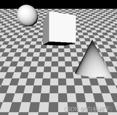 |
Now let's apply an affect to the entire scene. More precisely, to the View3D. When there are multiple View3D items in the scene, each has its own SceneEnvironment and therefore have their own post-processing effect chain. In the example there is one single View3D covering the entire window.
现在,让我们将效果应用于整个场景。更准确地说,到View3D。当场景中有多个View3D项目时,每个项目都有自己的SceneEnvironment,因此有自己的后处理效果链。在该示例中,有一个覆盖整个窗口的View3D。
| Change in main.qml | effect.frag |
|---|---|
environment: SceneEnvironment {
    backgroundMode: SceneEnvironment.Color
    clearColor: "black"
    effects: redEffect
}

Effect {
    id: redEffect
    property real uRed: 1.0
    NumberAnimation on uRed { from: 1; to: 0; duration: 5000; loops: -1 }
    passes: Pass {
        shaders: Shader {
            stage: Shader.Fragment
            shader: "effect.frag"
        }
    }
} | void MAIN()
{
vec4 c = texture(INPUT, INPUT_UV);
c.r = uRed;
FRAGCOLOR = c;
} |
This simple effect alters the red color channel value. Exposing QML properties as uniforms works the same way with effects as with custom materials. The shader starts with a line that is going to be very common when writing fragment shaders fro effects: sampling INPUT at the UV coordinates INPUT_UV. It then performs its desired calculations, and assigns the final fragment color to FRAGCOLOR.
这种简单的效果会更改红色通道的值。将QML属性作为uniforms进行曝光,其效果与自定义材质的效果相同。着色器以一条线开始,这条线在为效果编写片段着色器时非常常见:在UV坐标INPUT_UV处采样INPUT。然后,它执行所需的计算,并将最终片段颜色指定给FRAGCOLOR。
https://doc-snapshots.qt.io/qt6-dev/videos/quick3d-custom-first-effect-anim.mp4
Many properties set in the example are in plural (effects, passes, shaders). While the list [ ] syntax can be omitted when having a single element only, all these properties are lists, and can hold more than one element. Why is this?
示例中设置的许多特性有多种(效果、过程、着色器)。虽然只有一个元素时可以省略list[]语法,但所有这些属性都是列表,并且可以包含多个元素。为什么会这样?
- effects is a list, because View3D allows chaining multiple effects together. The effects are applied in the order in which they are added to the list. This allows easily applying two or more effects together to the View3D, and is similar to what one can achieve in Qt Quick by nesting ShaderEffect items. The
INPUTtexture of the next effect is always a texture that contains the previous effect's output. The output of the last effect in what gets used as the final output of the View3D. - 效果是一个列表,因为View3D允许将多个效果链接在一起。效果按添加到列表中的顺序应用。这允许轻松地将两个或多个效果一起应用到View3D,类似于在Qt Quick中通过嵌套ShaderEffect项可以实现的效果。下一个效果的INPUT纹理始终是包含上一个效果输出的纹理。用作View3D的最终输出的最后一个效果的输出。
- passes is a list, because unlike ShaderEffect, Effect has built-in support for multiple passes. A multi-pass effect is more powerful than chaining together multiple, independent effects in effects: a pass can output to a temporary, intermediate texture, which can then be used as input to subsequent passes, in addition to the original input texture of the effect. This allows creating complex effects that calculate, render, and blend together multiple textures in order to get to the final fragment color. This advanced use case is not going to be covered here. Refer to the Effect documentation page for details.
- 过程是一个列表,因为与ShaderEffect不同,Effect内置了对多个过程的支持。多过程效果比将效果中的多个独立效果链接在一起更强大:一个过程可以输出到临时的中间纹理,然后该纹理可以用作后续过程的输入,此外还有该效果的原始输入纹理。这允许创建复杂的效果,计算、渲染和混合多个纹理,以获得最终的片段颜色。这个高级用例不在这里讨论。有关详细信息,请参阅效果文档页面。
- shaders is a list, because an effect may have both a vertex and a fragment shader associated.
- 着色器是一个列表,因为一个效果可能同时关联顶点和片段着色器。
Chaining multiple effects
链接多重效果
Let's look at an example where the effect from the previous example gets complemented by another effect similar to the built-in DistortionSpiral effect.
让我们看一个例子,在这个例子中,上一个例子的效果得到了另一个类似于内置扭曲螺旋效果的效果的补充。
| Change in main.qml | effect2.frag |
|---|---|
environment: SceneEnvironment {
    backgroundMode: SceneEnvironment.Color
    clearColor: "black"
    effects: [redEffect, distortEffect]
}

Effect {
    id: redEffect
    property real uRed: 1.0
    NumberAnimation on uRed { from: 1; to: 0; duration: 5000; loops: -1 }
    passes: Pass {
        shaders: Shader {
            stage: Shader.Fragment
            shader: "effect.frag"
        }
    }
}

Effect {
    id: distortEffect
    property real uRadius: 0.1
    NumberAnimation on uRadius { from: 0.1; to: 1.0; duration: 5000; loops: -1 }
    passes: Pass {
        shaders: Shader {
            stage: Shader.Fragment
            shader: "effect2.frag"
        }
    }
} | void MAIN()
{
vec2 center_vec = INPUT_UV - vec2(0.5, 0.5);
center_vec.y *= INPUT_SIZE.y / INPUT_SIZE.x;
float dist_to_center = length(center_vec) / uRadius;
vec2 texcoord = INPUT_UV;
if (dist_to_center <= 1.0) {
float rotation_amount = (1.0 - dist_to_center) * (1.0 - dist_to_center);
float r = radians(360.0) * rotation_amount / 4.0;
float cos_r = cos(r);
float sin_r = sin(r);
mat2 rotation = mat2(cos_r, sin_r, -sin_r, cos_r);
texcoord = vec2(0.5, 0.5) + rotation * (INPUT_UV - vec2(0.5, 0.5));
}
vec4 c = texture(INPUT, texcoord);
FRAGCOLOR = c;
} |
https://doc-snapshots.qt.io/qt6-dev/videos/quick3d-custom-chained-effect-anim.mp4
Now the perhaps surprising question: why is this a bad example?
现在,也许令人惊讶的问题是:为什么这是一个糟糕的例子?
More precisely, it is not bad, but rather shows a pattern that can often be beneficial to avoid.
更准确地说,这并不是坏事,而是显示了一种通常可以避免的有益模式。
Chaining effects this way can be useful, but it is important to keep in mind the performance implications: doing two render passes (one to generate a texture with the adjusted red color channel, and then another one two calculate the distortion) is quite wasteful when one would be enough. If the fragment shader snippets were combined, the same result could have been achieved with one single effect.
这种方式的链接效果可能很有用,但重要的是要记住性能影响:进行两次渲染过程(一次使用调整后的红色通道生成纹理,然后再进行一次两次计算失真)是非常浪费的,而一次就足够了。如果将片段着色器片段组合在一起,则可以通过一个单独的效果获得相同的结果。
Defining Mesh and Texture Data from C++
从C++定义网格和纹理数据
Procedurally generating mesh and texture image data both follow similar steps:
生成网格和纹理图像数据的过程都遵循类似的步骤:
- Subclass QQuick3DGeometry or QQuick3DTextureData
- 子类QQuick3DGeometry或QQuick3DTextureData
- Set the desired vertex or image data upon construction by calling the protected member functions from the base class
- 通过从基类调用受保护的成员函数,在构造时设置所需的顶点或图像数据
- If dynamic changes are needed afterwards at some point, set the new data and call update()
- 如果以后某个时刻需要动态更改,请设置新数据并调用update()
- Once the implementation is done, the class needs to be registered to make it visible in QML
- 一旦实现完成,就需要注册该类,使其在QML中可见
- Model and Texture objects in QML can now use the custom vertex or image data provider by setting the Model::geometry or Texture::textureData property
- QML中的模型和纹理对象现在可以通过设置Model::geometry或Texture::textureData属性来使用自定义顶点或图像数据提供程序
Custom vertex data
自定义顶点数据
Vertex data refers to the sequence of (typically float) values that make up a mesh. Instead of loading .mesh files, a custom geometry provider is responsible for providing the same data. The vertex data consist of attributes, such as position, texture (UV) coordinates, or normals. The specification of attributes describes what kind of attributes are present, the component type (for example, a 3 component float vector for vertex position consisting of x, y, z values), which offset they start at in the provided data, and what the stride (the increment that needs to be added to the offset to point to the next element for the same attribute) is.
顶点数据是指组成网格的值序列(通常为浮点值)。自定义几何体提供程序负责提供相同的数据,而不是加载.mesh文件。顶点数据由属性组成,例如位置、纹理(UV)坐标或法线。属性的规范描述了存在的属性类型、组件类型(例如,由x、y、z值组成的顶点位置的3分量浮点矢量)、它们在所提供的数据中的起始偏移量以及步长(需要添加到偏移量以指向同一属性的下一个元素的增量)。
This may seem familiar if one has worked with graphics APIs, such as OpenGL or Vulkan directly, because the way vertex input is specified with those APIs maps loosely to what a .mesh file or a QQuick3DGeometry instance defines.
如果直接使用过图形API(如OpenGL或Vulkan),这似乎很熟悉,因为使用这些API指定顶点输入的方式会松散地映射到.mesh文件或QQuick3DGeometry实例定义的内容。
In addition, the mesh topology (primitive type) must be specified too. For indexed drawing, the data for an index buffer must be provided as well.
此外,还必须指定网格拓扑(基本体类型)。对于索引图形,还必须提供索引缓冲区的数据。
There is one built-in custom geometry implementation: the QtQuick3D.Helpers module includes a GridGeometry type. This allows rendering a grid in the scene with line primitives, without having to implement a custom QQuick3DGeometry subclass.
有一个内置的自定义几何体实现:QtQuick3D.Helpers模块包括GridGeometry类型。这允许使用线基元在场景中渲染网格,而不必实现自定义的QQuick3DGeometry子类。
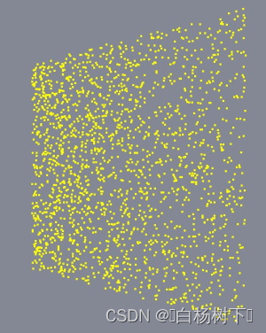
One other common use cases is rendering points. This is fairly simple to do since the attribute specification is going to be minimal: we provide three floats (x, y, z) for each vertex, nothing else. A QQuick3DGeometry subclass could implement a geometry consisting of 2000 points similarly to the following:
另一个常见的用例是渲染点。这相当简单,因为属性规范将是最小的:我们为每个顶点提供三个浮点(x,y,z),而不提供其他内容。QQuick3DGeometry子类可以实现由2000个点组成的几何体,类似于以下内容:
clear();
const int N = 2000;
const int stride = 3 * sizeof(float);
QByteArray v;
v.resize(N * stride);
float *p = reinterpret_cast<float *>(v.data());
QRandomGenerator *rg = QRandomGenerator::global();
for (int i = 0; i < N; ++i) {
const float x = float(rg->bounded(200.0f) - 100.0f) / 20.0f;
const float y = float(rg->bounded(200.0f) - 100.0f) / 20.0f;
*p++ = x;
*p++ = y;
*p++ = 0.0f;
}
setVertexData(v);
setStride(stride);
setPrimitiveType(QQuick3DGeometry::PrimitiveType::Points);
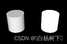
addAttribute(QQuick3DGeometry::Attribute::PositionSemantic, 0, QQuick3DGeometry::Attribute::F32Type);Combined with a material of
与的材料组合
DefaultMaterial {
    lighting: DefaultMaterial.NoLighting
    cullMode: DefaultMaterial.NoCulling
    diffuseColor: "yellow"
    pointSize: 4
}
the end result is similar to this (here viewed from an altered camera angle, with the help of WasdController):
最终结果与此类似(在WasdController的帮助下,从改变的相机角度观察):
Note: Be aware that point sizes and line widths other than 1 may not be supported at run time, depending on the underlying graphics API. This is not something Qt has control over. Therefore, it can become necessary to implement alternative techniques instead of relying on point and line drawing.
注意:请注意,运行时可能不支持1以外的点大小和线宽,具体取决于底层图形API。这不是Qt所能控制的。因此,有必要实施替代技术,而不是依赖于点和线绘制。
Custom texture data
自定义纹理数据
With textures, the data that needs to be provided is a lot simpler structurally: it is the raw pixel data, with a varying number of bytes per pixel, depending on the texture format. For example, an RGBA texture expects four bytes per pixel, whereas RGBA16F is four half-floats per pixel. This is similar to what a QImage stores internally. However, Qt Quick 3D textures can have formats the data for which cannot be represented by a QImage. For example, floating point HDR textures, or compressed textures. Therefore the data for QQuick3DTextureData is always provided as a raw sequence of bytes. This may seem familiar if one has worked with graphics APIs, such as OpenGL or Vulkan directly.
对于纹理,需要提供的数据在结构上要简单得多:它是原始像素数据,每个像素的字节数不同,具体取决于纹理格式。例如,RGBA纹理期望每个像素有四个字节,而RGBA16F是每个像素四个半浮点。这与QImage内部存储的内容类似。然而,Qt Quick 3D纹理可能具有无法由QImage表示的数据格式。例如,浮点HDR纹理或压缩纹理。因此,QQuick3DTextureData的数据总是作为原始字节序列提供。如果直接使用过图形API(如OpenGL或Vulkan),这可能看起来很熟悉。
For details, refer to the QQuick3DGeometry and QQuick3DTextureData documentation pages.
有关详细信息,请参阅QQuick3DGeometry和QQuick3DTextureData文档页面。
See also CustomMaterial, Effect, QQuick3DGeometry, QQuick3DTextureData, Qt Quick 3D - Custom Effect Example, Qt Quick 3D - Custom Shaders Example, Qt Quick 3D - Custom Materials Example, Qt Quick 3D - Custom Geometry Example, and Qt Quick 3D - Procedural Texture Example.
另请参见自定义材质、效果、QQuick3DGeometry、QQuick3D TextureData、Qt Quick 3D-自定义效果示例、Qt Quick3D-自定义着色器示例、Qt-Quick 3D-定制材质示例、Qt-Quick 3D-定制化几何体示例和Qt-Quick 3D-过程纹理示例。
© 2024 The Qt Company Ltd. Documentation contributions included herein are the copyrights of their respective owners. The documentation provided herein is licensed under the terms of the GNU Free Documentation License version 1.3 as published by the Free Software Foundation. Qt and respective logos are trademarks of The Qt Company Ltd. in Finland and/or other countries worldwide. All other trademarks are property of their respective owners.


 5053
5053

 被折叠的 条评论
为什么被折叠?
被折叠的 条评论
为什么被折叠?
 到【灌水乐园】发言


