


板级支持包(BSP)是介于主板硬件和操作系统中驱动层程序之间的一层,一般认为它属于操作系统的一部分,主要是实现对操作系统的支持,为上层的驱动程序提供访问硬件设备寄存器的函数包,使之能够更好地运行于硬件主板
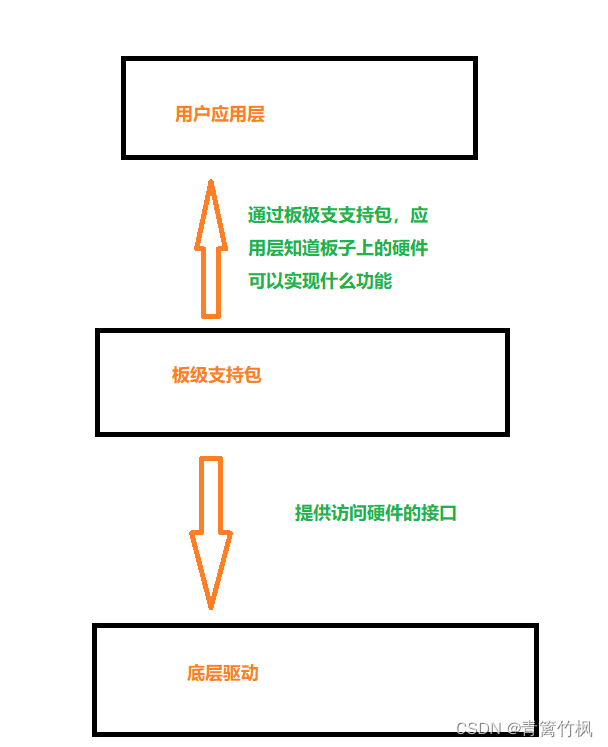
以按键点亮LED为例,可以理解为板极支持包为底层驱动(HAL)库提供可以访问硬件的接口,同时,当再用户应用层编写应用程序实现按下按键点亮LED时,要通过板级支持包知道板子上的硬件有那些功能可以实现,比如不需要了解GPIO的结构,只要知道调用某个方法可以实现某个功能就行
构建开发板上的LED的灯板级支持包
以CubeMX创建的项目为例
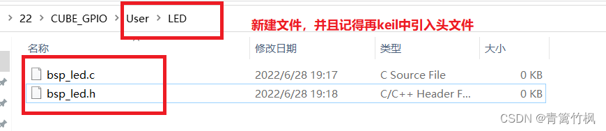
首先创建一个user文件夹,创建2个文件
以上步骤准备好,既可以开始构建板级支持包
要实现的功能:初始化GPIO,点亮,熄灭,翻转LED灯的状态,LED绿灯用到PB0,蓝灯用PB1,红灯用PB5. 编写代码主要涉及两个文件,主程序bsp_led.c,用来使能和初始化GPIO,配置引脚输出模式,bsp_led.h用于具体分配引脚的功能,最后在main.c文件中写入预期实现的功能并执行代码
一.bsp_led.c文件代码编写过程
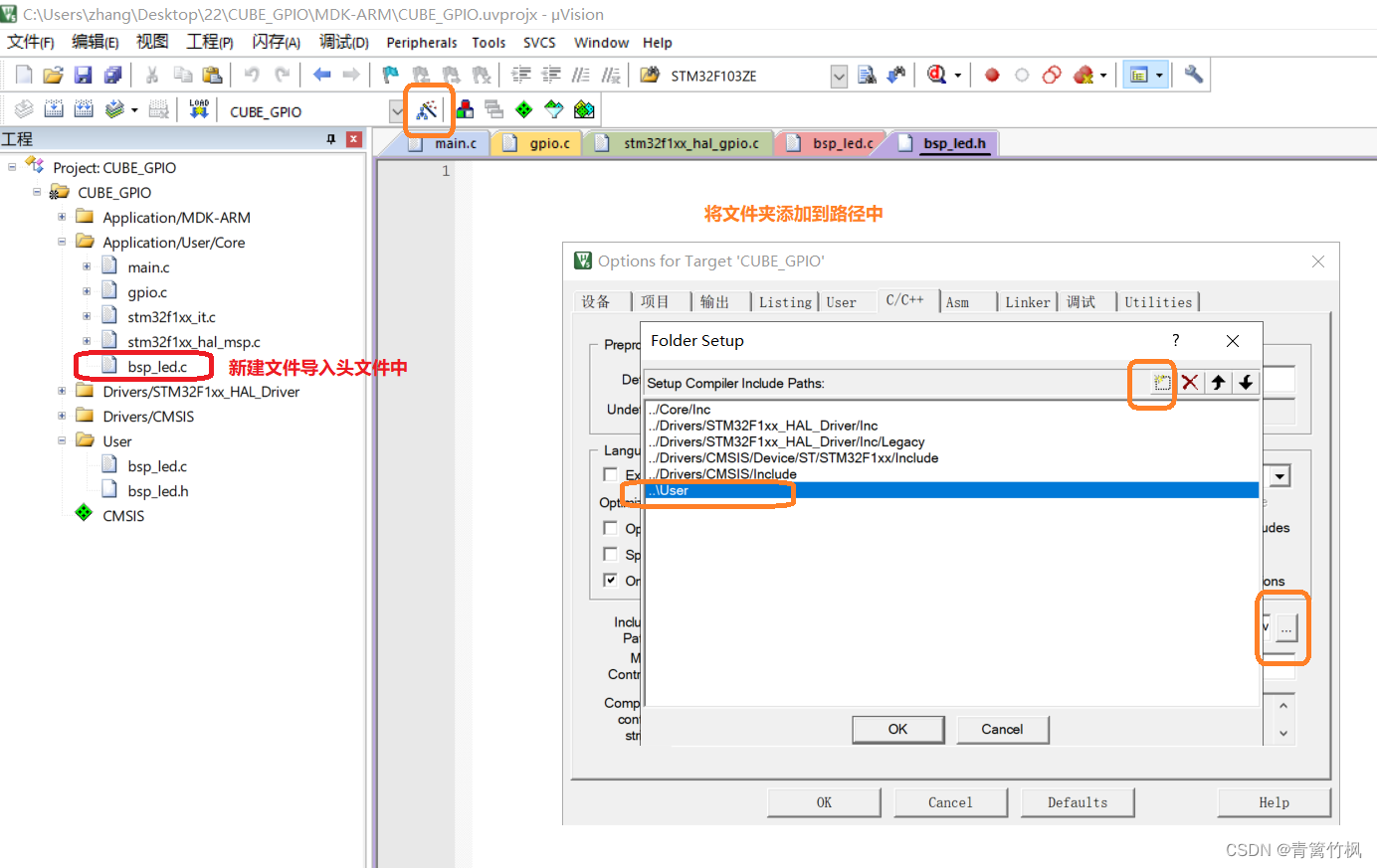
1.添加头文件路径,确保右键可以正常跳转
//添加头文件路径
#include "./led/bsp_led.h"
2.初始化GPIO
//初始化GPIO
void LED_GPIO_Init(void)
{

}
2.1首先要使能GPIO,去stm32f1xx_hal_gpio.c文件查看使能方法
如图,使能GPIO要用到_HAL_RCC_GPIOx_CLK_ENABLE(),
//添加头文件路径
#include "./led/bsp_led.h"

//初始化GPIO
void LED_GPIO_Init(void)
{
	  __HAL_RCC_GPIOB_CLK_ENABLE();


}
使能之后,如果
3.配置引脚
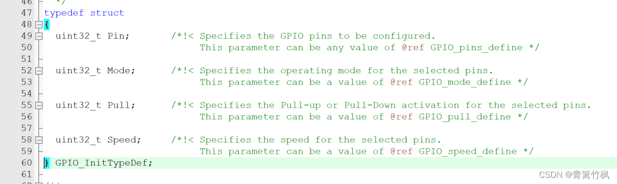
(1)配置IO模式,要使用GPIO_InitTypeDef结构体,因此搜索GPIO_InitTypeDef查看这个结构体的用法,经过搜索,这些内容在stm32f1xx_hal_gpio.h文件中
(2)配置上拉,下拉等模式,要用到GPIO_InitTypeDef结构体,结构体内容如图所示
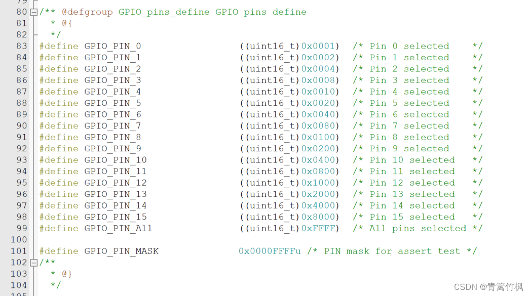
要实例化GPIO针脚,要查询GPIO_pins_define,以下查询了GPIO_pins_define,GPIO_mode_define,GPIO_pull_define,GPIO_SpeedDefine
GPIO_pins_define
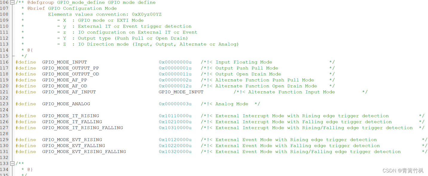
GPIO_mode_define
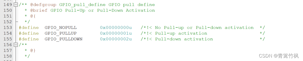
GPIO_pull_define
GPIO_speed_define
//添加头文件路径
#include "./led/bsp_led.h"

//初始化GPIO
void LED_GPIO_Init(void)
{
	//GPIO初始化结构体对象
	GPIO_InitTypeDef LED_GPIO_Init;

	  __HAL_RCC_GPIOB_CLK_ENABLE();


//根据以上资料配置引脚
LED_GPIO_Init.Mode=GPIO_MODE_OUTPUT_PP;
LED_GPIO_Init.Pin=GPIO_PIN_0|GPIO_PIN_11|GPIO_PIN_5;
LED_GPIO_Init.Pull=GPIO_NOPULL;
LED_GPIO_Init.Speed=GPIO_SPEED_FREQ_LOW;

}
3.将结构体传递给初始化函数,搜索初始化函数 ,查看传递方式
HAL_GPIO_Init
完整代码如下
//添加头文件路径
#include "./led/bsp_led.h"
//初始化GPIO
void LED_GPIO_Init(void)
{
//GPIO初始化结构体对象
GPIO_InitTypeDef LED_GPIO_Init;
//查看stm32f1xx_hal_gpio.c文件的50行,了解如何设置驱动
//(#) Enable the GPIO APB2 clock using the following function : __HAL_RCC_GPIOx_CLK_ENABLE().
//复制 : __HAL_RCC_GPIOx_CLK_ENABLE().由于用到GPIOB,故改为以下代码
__HAL_RCC_GPIOB_CLK_ENABLE();
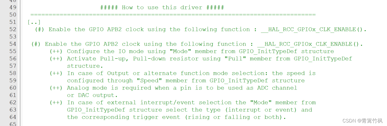
//具体配置方法看这里,按照说明文件的指示查找相应的配置方法
// (#) Enable the GPIO APB2 clock using the following function : __HAL_RCC_GPIOx_CLK_ENABLE().
// (++) Configure the IO mode using "Mode" member from GPIO_InitTypeDef structure
// (++) Activate Pull-up, Pull-down resistor using "Pull" member from GPIO_InitTypeDef
// structure.
// (++) In case of Output or alternate function mode selection: the speed is
// configured through "Speed" member from GPIO_InitTypeDef structure
// (++) Analog mode is required when a pin is to be used as ADC channel
// or DAC output.
// (++) In case of external interrupt/event selection the "Mode" member from
// GPIO_InitTypeDef structure select the type (interrupt or event) and
// the corresponding trigger event (rising or falling or both).
//为了用GPIO初始化结构体赋值,找GPIO_InitTypeDef所在的文件stm32f1xx_hal_gpio.h,找到的内容如下
// typedef struct
//{
// uint32_t Pin; /*!< Specifies the GPIO pins to be configured.
// This parameter can be any value of @ref GPIO_pins_define */
// uint32_t Mode; /*!< Specifies the operating mode for the selected pins.
// This parameter can be a value of @ref GPIO_mode_define */
// uint32_t Pull; /*!< Specifies the Pull-up or Pull-Down activation for the selected pins.
// This parameter can be a value of @ref GPIO_pull_define */
// uint32_t Speed; /*!< Specifies the speed for the selected pins.
// This parameter can be a value of @ref GPIO_speed_define */
//} GPIO_InitTypeDef;
//再找GPIO_pins_define文件,结果如下
/** @defgroup GPIO_pins_define GPIO pins define
* @{
*/
//#define GPIO_PIN_0 ((uint16_t)0x0001) /* Pin 0 selected */
//#define GPIO_PIN_1 ((uint16_t)0x0002) /* Pin 1 selected */
//#define GPIO_PIN_2 ((uint16_t)0x0004) /* Pin 2 selected */
//#define GPIO_PIN_3 ((uint16_t)0x0008) /* Pin 3 selected */
//#define GPIO_PIN_4 ((uint16_t)0x0010) /* Pin 4 selected */
//#define GPIO_PIN_5 ((uint16_t)0x0020) /* Pin 5 selected */
//#define GPIO_PIN_6 ((uint16_t)0x0040) /* Pin 6 selected */
//#define GPIO_PIN_7 ((uint16_t)0x0080) /* Pin 7 selected */
//#define GPIO_PIN_8 ((uint16_t)0x0100) /* Pin 8 selected */
//#define GPIO_PIN_9 ((uint16_t)0x0200) /* Pin 9 selected */
//#define GPIO_PIN_10 ((uint16_t)0x0400) /* Pin 10 selected */
//#define GPIO_PIN_11 ((uint16_t)0x0800) /* Pin 11 selected */
//#define GPIO_PIN_12 ((uint16_t)0x1000) /* Pin 12 selected */
//#define GPIO_PIN_13 ((uint16_t)0x2000) /* Pin 13 selected */
//#define GPIO_PIN_14 ((uint16_t)0x4000) /* Pin 14 selected */
//#define GPIO_PIN_15 ((uint16_t)0x8000) /* Pin 15 selected */
//#define GPIO_PIN_All ((uint16_t)0xFFFF) /* All pins selected */
//#define GPIO_PIN_MASK 0x0000FFFFu /* PIN mask for assert test */
///**
// * @}
// */
//找到GPIO_mode_define
//#define GPIO_MODE_INPUT 0x00000000u /*!< Input Floating Mode */
//#define GPIO_MODE_OUTPUT_PP 0x00000001u /*!< Output Push Pull Mode */
//#define GPIO_MODE_OUTPUT_OD 0x00000011u /*!< Output Open Drain Mode */
//#define GPIO_MODE_AF_PP 0x00000002u /*!< Alternate Function Push Pull Mode */
//#define GPIO_MODE_AF_OD 0x00000012u /*!< Alternate Function Open Drain Mode */
//#define GPIO_MODE_AF_INPUT GPIO_MODE_INPUT /*!< Alternate Function Input Mode */
//#define GPIO_MODE_ANALOG 0x00000003u /*!< Analog Mode */
//#define GPIO_MODE_IT_RISING 0x10110000u /*!< External Interrupt Mode with Rising edge trigger detection */
//#define GPIO_MODE_IT_FALLING 0x10210000u /*!< External Interrupt Mode with Falling edge trigger detection */
//#define GPIO_MODE_IT_RISING_FALLING 0x10310000u /*!< External Interrupt Mode with Rising/Falling edge trigger detection */
//#define GPIO_MODE_EVT_RISING 0x10120000u /*!< External Event Mode with Rising edge trigger detection */
//#define GPIO_MODE_EVT_FALLING 0x10220000u /*!< External Event Mode with Falling edge trigger detection */
//#define GPIO_MODE_EVT_RISING_FALLING 0x10320000u /*!< External Event Mode with Rising/Falling edge trigger detection */
//找到GPIO_pull_define
//#define GPIO_NOPULL 0x00000000u /*!< No Pull-up or Pull-down activation */
//#define GPIO_PULLUP 0x00000001u /*!< Pull-up activation */
//#define GPIO_PULLDOWN 0x00000002u /*!< Pull-down activation */
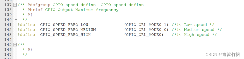
//找到GPIO_speed_define
//#define GPIO_SPEED_FREQ_LOW (GPIO_CRL_MODE0_1) /*!< Low speed */
//#define GPIO_SPEED_FREQ_MEDIUM (GPIO_CRL_MODE0_0) /*!< Medium speed */
//#define GPIO_SPEED_FREQ_HIGH (GPIO_CRL_MODE0) /*!< High speed */
//根据以上资料配置引脚
LED_GPIO_Init.Mode=GPIO_MODE_OUTPUT_PP;
LED_GPIO_Init.Pin=GPIO_PIN_0|GPIO_PIN_11|GPIO_PIN_5;
LED_GPIO_Init.Pull=GPIO_NOPULL;
LED_GPIO_Init.Speed=GPIO_SPEED_FREQ_LOW;
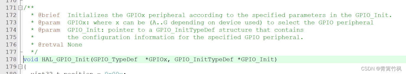
//接下来,将结构体传递给初始化函数,先去搜索初始化函数,找到所在的文件stm32f1xx_hal_gpio,找到的内容如下
/**
* @brief Initializes the GPIOx peripheral according to the specified parameters in the GPIO_Init.
* @param GPIOx: where x can be (A..G depending on device used) to select the GPIO peripheral
* @param GPIO_Init: pointer to a GPIO_InitTypeDef structure that contains
* the configuration information for the specified GPIO peripheral.
* @retval None
*/
//void HAL_GPIO_Init(GPIO_TypeDef *GPIOx, GPIO_InitTypeDef *GPIO_Init)
HAL_GPIO_Init(GPIOB,&LED_GPIO_Init);
//到此,GPIO初始化完毕
}
二.bsp_led.h文件代码编写过程
1.预定义,防止头文件被重复调用,并声明一个实现函数初始化功能的函数
//预定义,防止头文件被重复引用
#ifndef _BSP_LED_H_
#define _BSP_LED_H_


//声明一个函数,实现GPIO功能,在这里将LED灯对应的GPIO引脚初始化
void LED_GPIO_Init(void);

#endif
2.要使用HAL库,因此引入如下头文件
//预定义,防止头文件被重复引用
#ifndef _BSP_LED_H_
#define _BSP_LED_H_

//为了使用HAL库,要引用这个头文件
#include "stm32f1xx.h"


//声明一个函数,实现GPIO功能,在这里将LED灯对应的GPIO引脚初始化
void LED_GPIO_Init(void);


#endif
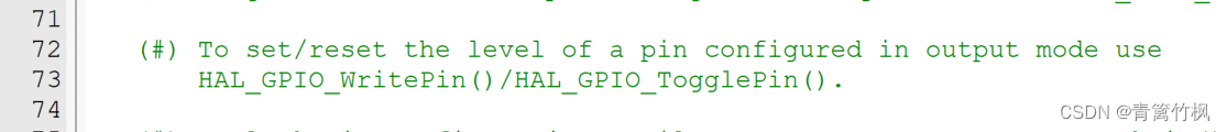
3.通过控制高低电平控制LED灯,需要使用GPIO,因此,要去stm32f1xx_hal_gpio.c文件中查找引脚的设置方法,stm32f1xx_hal_gpio.c给出了设置高低电平要用到的方法,接下来,去查找HAL_GPIO_WritePin()和HAL_GPIO_TogglePIN(),查看使用方法,以及要传入哪些参数
以下是查找的结果
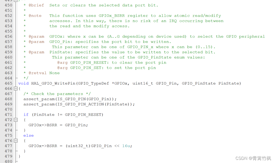
HAL_GPIO_WritePin()的使用方法,要使用的参数包括GPIO结构体指针,针脚,以及针脚状态
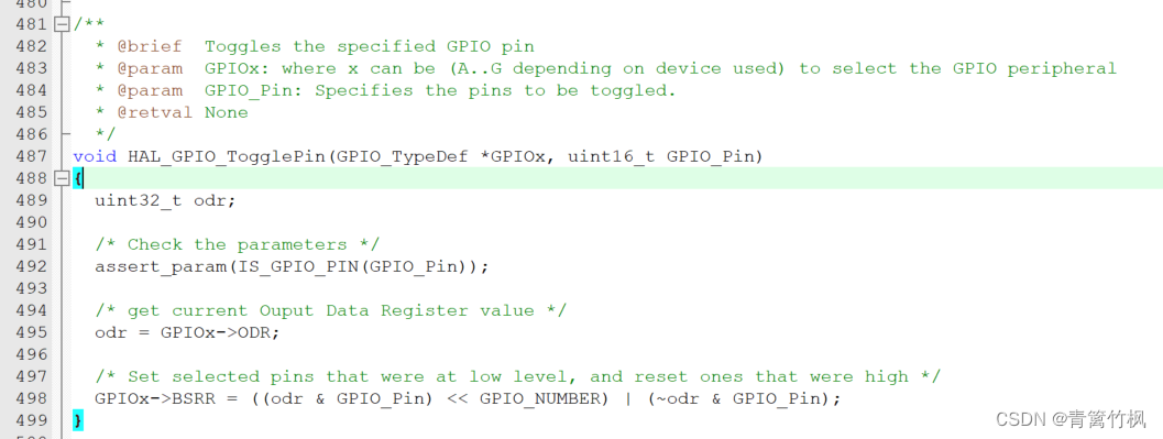
HAL_GPIO_TogglePin()的使用方法,要传入的类型包括,GPIO结构体指针,以及针脚
随后,设置阵脚的开,关以及翻转状态,总体代码如下
//预定义,防止头文件被重复引用
#ifndef _BSP_LED_H_
#define _BSP_LED_H_

//为了使用HAL库,要引用这个头文件
#include "stm32f1xx.h"
//设置LED灯的状态,去stm32f1xx_hal_gpio.c文件查找设置方法,结果如下
//   (#) To set/reset the level of a pin configured in output mode use
//       HAL_GPIO_WritePin()/HAL_GPIO_TogglePin().

//接着查找 HAL_GPIO_WritePin,查看需要传入的参数,结果如下(465行)
//void HAL_GPIO_WritePin(GPIO_TypeDef *GPIOx, uint16_t GPIO_Pin, GPIO_PinState PinState)
//完成设置,设置输出低电平,加do...while结构保证语句只执行一次
#define LED_R_ON do{HAL_GPIO_WritePin(GPIOB,GPIO_PIN_5,GPIO_PIN_RESET);}while(0);
//实现LED熄灭
#define LED_R_OFF do{HAL_GPIO_WritePin(GPIOB,GPIO_PIN_5,GPIO_PIN_SET);}while(0);

//实现LED的翻转
/**
  * @brief  Toggles the specified GPIO pin
  * @param  GPIOx: where x can be (A..G depending on device used) to select the GPIO peripheral
  * @param  GPIO_Pin: Specifies the pins to be toggled.
  * @retval None
  */
//void HAL_GPIO_TogglePin(GPIO_TypeDef *GPIOx, uint16_t GPIO_Pin)
#define LED_R_Toggle do{HAL_GPIO_TogglePin(GPIOB,GPIO_PIN_5);}while(0);

//绿灯
#define LED_G_ON do{HAL_GPIO_WritePin(GPIOB,GPIO_PIN_0, GPIO_PIN_RESET);}while(0);
#define LED_G_OFF do{HAL_GPIO_WritePin(GPIOB,GPIO_PIN_0, GPIO_PIN_SET);}while(0);
#define LED_G_Toggle do{HAL_GPIO_TogglePin(GPIOB,GPIO_PIN_0);}while(0);

//蓝灯
#define LED_B_ON do{HAL_GPIO_WritePin(GPIOB,GPIO_PIN_1, GPIO_PIN_RESET);}while(0);
#define LED_B_OFF do{HAL_GPIO_WritePin(GPIOB,GPIO_PIN_1,GPIO_PIN_SET);}while(0);
#define LED_B_Toggle do{HAL_GPIO_TogglePin(GPIOB,GPIO_PIN_1);}while(0);

//声明一个函数,实现GPIO功能,在这里将LED灯对应的GPIO引脚初始化
void LED_GPIO_Init(void);
//LED灯使用PB0,PB1,PB5三个引脚

#endif
三.引入main.c文件并执行
1.引入板级支持包头文件

2.引入初始化函数并写入想要实现的功能
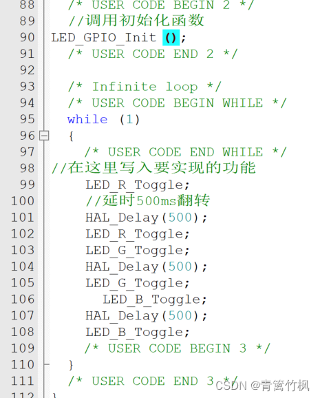
在板级支持包中实现了对板子的引脚的分配以及完成了相关功能的函数,在main.c中只需要调用这些函数,就能实现相应的功能


 973
973


 被折叠的 条评论
为什么被折叠?
被折叠的 条评论
为什么被折叠?
 到【灌水乐园】发言


