


本教程基于up主江科大自化协——“STM32入门教程”记录的个人学习笔记
1.时钟配置和端口的调用配置
#include "stm32f10x.h" // Device header
int main (void)
{
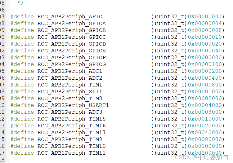
RCC_APB2PeriphClockCmd(RCC_APB2Periph_GPIOA,ENABLE);//RCC APB2外设时钟控制(选择外设端口,使能或失能)
GPIO_InitTypeDef GPIO_InitStruct;//GPIO_InitStruct是一个结构体,通过下方引出结构的参数
GPIO_InitStruct.GPIO_Mode=GPIO_Mode_Out_PP;//端口输出的模式
GPIO_InitStruct.GPIO_Pin=GPIO_Pin_0;//端口定义引脚
GPIO_InitStruct.GPIO_Speed=GPIO_Speed_50MHz;//端口频率(默认50MHZ)
GPIO_Init(GPIOA,&GPIO_InitStruct);
//代码效果:GPIOA外设的0号引脚自动配置为推挽输出,50MHZ的速度
常用RCC库函数:(具体看定义)
RCC_AHBPeriphClockCmd(uint32_t RCC_AHBPeriph, FunctionalState NewState)
//RCC AHB 外设时钟控制(选择外设,使能或失能)
RCC_APB2PeriphClockCmd(uint32_t RCC_APB2Periph, FunctionalState NewState);//RCC APB2 外设时钟控制
RCC_APB1PeriphClockCmd(uint32_t RCC_APB1Periph, FunctionalState NewState);
//RCC APB1 外设时钟控制
GPIO常用库函数:
void GPIO_DeInit(GPIO_TypeDef* GPIOx);
//所指定的GPIO外设会被复位
void GPIO_AFIODeInit(void);//所指定的AFIO外设会被复位
void GPIO_Init(GPIO_TypeDef* GPIOx, GPIO_InitTypeDef* GPIO_InitStruct);//用结构体的参数来初始化GPIO口,(一般结构的需要定义,并赋值调用,具体看上述代码)
void GPIO_StructInit(GPIO_InitTypeDef* GPIO_InitStruct);//把结构体变量赋一个默认值
uint8_t GPIO_ReadInputDataBit(GPIO_TypeDef* GPIOx, uint16_t GPIO_Pin);uint16_t GPIO_ReadInputData(GPIO_TypeDef* GPIOx);
uint8_t GPIO_ReadOutputDataBit(GPIO_TypeDef* GPIOx, uint16_t GPIO_Pin);
uint16_t GPIO_ReadOutputData(GPIO_TypeDef* GPIOx);//上述四个是GPIO的读取函数
void GPIO_SetBits(GPIO_TypeDef* GPIOx, uint16_t GPIO_Pin);
void GPIO_ResetBits(GPIO_TypeDef* GPIOx, uint16_t GPIO_Pin);
void GPIO_WriteBit(GPIO_TypeDef* GPIOx, uint16_t GPIO_Pin, BitAction BitVal);
void GPIO_Write(GPIO_TypeDef* GPIOx, uint16_t PortVal);//上述四个是GPIO的写入函数
GPIO_PinLockConfig(GPIO_TypeDef* GPIOx, uint16_t GPIO_Pin);
//锁定GPIO配置,调用此函数,该引脚配置就会被锁定,防止意外更改
GPIO_EventOutputConfig(uint8_t GPIO_PortSource, uint8_t GPIO_PinSource);
GPIO_EventOutputCmd(FunctionalState NewState);//配置AFIO事件输出功能
GPIO_PinRemapConfig(uint32_t GPIO_Remap, FunctionalState NewState);
//引脚重映射(映射的方式,新的状态)
GPIO_EXTILineConfig(uint8_t GPIO_PortSource, uint8_t GPIO_PinSource);//配置AFIO数据选择器,选择需要中断的引脚
GPIO_ETH_MediaInterfaceConfig(uint32_t GPIO_ETH_MediaInterface);
//配置以太网外设
端口GPIO的工作模式
GPIO_Mode_AIN //模拟输入
GPIO_Mode_IN_FLOATING //浮空输入
GPIO_Mode_IPD //下拉输入
GPIO_Mode_IPU //上拉输入
GPIO_Mode_Out_OD //开漏输出
GPIO_Mode_Out_PP //推挽输出
GPIO_Mode_AF_OD //复用开漏
GPIO_Mode_AF_PP//复用推挽
写入函数
void GPIO_SetBits(GPIO_TypeDef* GPIOx, uint16_t GPIO_Pin);
//把指定端口设置为高电平
void GPIO_ResetBits(GPIO_TypeDef* GPIOx, uint16_t GPIO_Pin);//把指定端口设置成低电平
void GPIO_WriteBit(GPIO_TypeDef* GPIOx, uint16_t GPIO_Pin, BitAction BitVal);//可以自定义端口为高电平或低电平(BitAction BitVal——Bit-RESET或Bit-SET)
void GPIO_Write(GPIO_TypeDef* GPIOx, uint16_t PortVal);
2.端口引脚设置
需要同时调用多个端口,可以采用端口“按位或”的操作方式
GPIO_InitStruct.GPIO_Pin=GPIO_Pin_0|GPIO_Pin_1|GPIO_Pin_2;//多个端口定义引脚因为端口采用一位对应着一个端口,即0000 0000 0000 0001表示Pin-0
0000 0000 0000 0010表示Pin-1
依次类推
因此,当端口通过“按位或”的方式,即0000 0000 0000 0011就表示Pin-0,Pin-1同时开启。

同样的道理:

时钟控制也可以通过“按位或 ”的方式控制
GPIO_SetBits,GPIO_ResetBits也是同样的道理
3.流水灯点亮程序
#include "stm32f10x.h"                  // Device header
#include "Delay.h"
int main (void)
{
	RCC_APB2PeriphClockCmd(RCC_APB2Periph_GPIOA,ENABLE);
	GPIO_InitTypeDef GPIO_InitStruct;//GPIO_InitStruct是一个结构体,通过下方引出结构的参数
	GPIO_InitStruct.GPIO_Mode=GPIO_Mode_Out_PP;
	GPIO_InitStruct.GPIO_Pin=GPIO_Pin_All;
	GPIO_InitStruct.GPIO_Speed=GPIO_Speed_50MHz;
	GPIO_Init(GPIOA,&GPIO_InitStruct);


	while(1)
	{
		GPIO_Write(GPIOA,~0X0001);//0000 0000 0000 0001,~是按位取反符号,低电平点亮
		Delay_ms(500);
		GPIO_Write(GPIOA,~0X0002);//0000 0000 0000 0010,
		Delay_ms(500);
		GPIO_Write(GPIOA,~0X0004);//0000 0000 0000 0100,
		Delay_ms(500);
		GPIO_Write(GPIOA,~0X0008);//0000 0000 0000 1000,
		Delay_ms(500);
		GPIO_Write(GPIOA,~0X0010);//0000 0000 0001 0000,
		Delay_ms(500);
		GPIO_Write(GPIOA,~0X0020);//0000 0000 0010 0000,
		Delay_ms(500);
		GPIO_Write(GPIOA,~0X0040);//0000 0000 0100 0000,
		Delay_ms(500);
		GPIO_Write(GPIOA,~0X0080);//0000 0000 1000 0000,
		Delay_ms(500);

	}
}
4.蜂鸣器
#include "stm32f10x.h"                  // Device header
#include "Delay.h"
int main (void)
{
	RCC_APB2PeriphClockCmd(RCC_APB2Periph_GPIOB,ENABLE);
	GPIO_InitTypeDef GPIO_InitStruct;//GPIO_InitStruct是一个结构体,通过下方引出结构的参数
	GPIO_InitStruct.GPIO_Mode=GPIO_Mode_Out_PP;
	GPIO_InitStruct.GPIO_Pin=GPIO_Pin_12;
	GPIO_InitStruct.GPIO_Speed=GPIO_Speed_50MHz;
	GPIO_Init(GPIOB,&GPIO_InitStruct);


	while(1)
	{
		GPIO_ResetBits(GPIOB,GPIO_Pin_12);
		Delay_ms(500);
		GPIO_SetBits(GPIOB,GPIO_Pin_12);
		Delay_ms(500);

	}
}


 2311
2311


 被折叠的 条评论
为什么被折叠?
被折叠的 条评论
为什么被折叠?
 到【灌水乐园】发言


