


显示屏控制方式有两种,一是同步控制方式,二是异步控制方式。同步控制方式是指:屏同步显示Frambuffer的内容,是实时变化的;异步控制方式就是屏显示已经发送在卡上的固定内容(显示屏平时无需IPU进行刷新,显示屏有内置CPU,能独立运行刷新动作)。
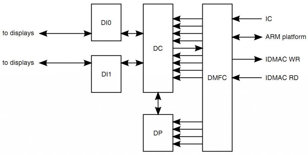
The display port handles all the IPU features targeted for controlling and sending data to the display. The display port consists of 4 modules.
DC - a display controller,
DP - a display processor,
DMFC - a display multi-FIFO controller
DI - a display interface. The DI is instantiated twice to provide two symmetrical display interfaces.
TI DM3730显示框图

我们的显示框图
Display ports channels
The display port send data to the display over several channels. The data source may be the system's memory (via the IDMAC) the IC block and the ARM platform. The display port can read data from the display and send it to the ARM platform or IDMAC
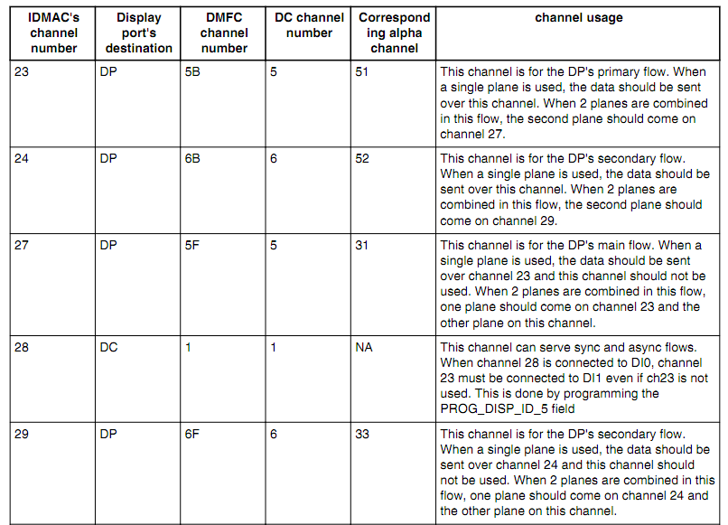
代码通道管理宏定义:
MEM_BG_SYNC = _MAKE_CHAN(9, 23, NO_DMA, 51, NO_DMA),
MEM_FG_SYNC = _MAKE_CHAN(10, 27, NO_DMA, 31, NO_DMA),
MEM_BG_ASYNC0 = _MAKE_CHAN(11, 24, NO_DMA, 52, NO_DMA),
MEM_FG_ASYNC0 = _MAKE_CHAN(12, 29, NO_DMA, 33, NO_DMA),
The Display Multi Fifo Control manages Multi channels FIFOs. The DMFC serves the following clients:
• IDMAC - both read and write
• DP - read only
• DC - both read and write
• IC - write only
• AHB - both read and write
The DP and the DC read channels are physically attached to an IDMAC or an IC channel. As the IC has only one output channel connected to the DMFC. When the input is coming from the IC it replaces a channel that was physically attached to the IDMAC. The DMFC uses a single physical memory that serves the DP and DC read channels. The AHB accesses to the DC and the DC's write channel (read from display) use a separate physical memory.
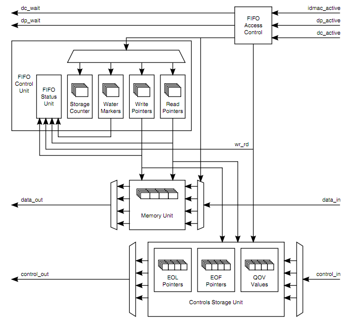
上面框图反映了数据读取到DC与DP的相关支持模块与逻辑。通过AXI总线突发模式读取到的数据被缓冲到该FIFO存储单元。FIFO控制(AXI总线写入、DC/DP读取)
This field defines the watermark's level of the DMFC write FIFO. Crossing this level will send the watermark signal to the IDMAC. 当数据低于水位下限请求数据读取。高于停止。
FIFO宽度为128bit深度为512,可分为8端,对应8路DMA传输缓冲。
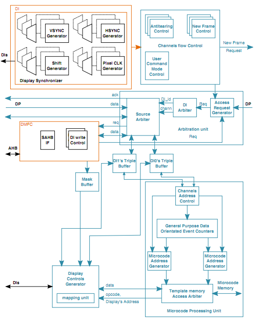
DP - Display Processor
The display processor processes the image prior to sending it to the display. The main task performed by the DP is combining between 2 planes. The DP has 2 input FIFOs holding the data of full plane and the partial plane. In addition the DP performs some image enhancement functions like gamma correction, Color space conversion including Gamut mapping.

DC - Display Controller
IPU handles few display flows supporting few displays. The IPU's flows' data sources can be the ARM platform, the system's memory, a camera or an external device connected on the display's port such as an external graphic accelerator. The data's destination can be any device connected on one of the DI ports.
The DC controls the flows coming to and from the DI port. The DC manages the flows, decides which flows are currently active and when each flow is activated. The arbitrates between the active flows, gets the data from the predefined source and distribute it to the correct DI.
功能:
-
输出到DI仲裁控制
For asynchronous flows the scheduling is done according to a request coming from the Frame Synchronization Unit (FSU) on the control sub-block (CM).
For Synchronous flows the scheduling is done according to a trigger that is generated by a timer located on the one of the display's interface blocks (DI)
访问优先级:
-
Channels flow control
New Frame control :同步异步模式帧切换控制,异步模式CM模块使能切换,同步模式DI模块使能切换。
Antitearing control:
The supported tearing elimination triggers can be:
• An internally generated VSYNC signal
• A VSYNC signal generated by the display. The data source is the memory.
• A VSYNC signal coming from the CSI
User command mode control:
A user may prepare in the system's memory a buffer that holds commends to be sent to the external device. The command buffer includes the same amount of lines as the data buffer. The line of commands are sent to the display line by line. A line of data is sent following each line of commands. This mode is activated by programming the PROG_CHAN_TYP of the corresponding channel.
-
Arbitration Unit
This unit arbitrates the requests coming from the DMFC and from the DP and sends them to corresponding DI.
Access request generator:The requests coming from the DMFC or DP are sorted according to the target DI and then served according to a hard coded priority. The priority order is Sync flow, ARM platform access, IDMAC's Async flows.
DI arbiter:This units arbitrates between the DIs. The priority is hard coded. The priority order is Sync flow, ARM platform access, IDMAC's Async flows.
Source arbiter:Once the source of the request to be served was selected and the target DI was chosen, this unit routes the request and all the signals, associated with it, to the correct triple buffer and to the correct source of the data.
-
Microcode processing unit
The main control unit of the DC is the Microcode processing unit (MPU). The data coming to the DC may be associated with some additional information like new frame, new line, new address etc. The information is processed in the MPU. The MPU executes the associated routine. The routine includes a set of instructions of the actions to be performed by the DC and DI.
Channels address control:This unit controls the display's address for each channel. This unit is responsible fordefining the next address to be accessed (by incrementing or jumping). Stores specialevents flags (like EOF, EOL etc.). Based on the display's address and the special events,the type of the routines to be executed is defined.
General purpose Data oriented events counters:A user may define up to 4 general purpose events. The events are triggered by a standard event (NF, NL). The standard event restarts a counter, when the counter completes counting the user's general purpose event is asserted. This event activates a routine like any other events.
DC_EVT_NF DC_EVT_EOF
DC_EVT_NL DC_EVT_EOL
DC_EVT_NFIELD DC_EVT_EOFIELD
DC_EVT_NEW_ADDR
DC_EVT_NEW_CHAN
DC_EVT_NEW_DATA
Microcode address generator:
Template's Memory Access Arbiter:This unit gets memory access requests from the 2 microcode address generator units and arbitrates between them in a Round Robin fashion. In case that only one of the requests belongs to a synchronous flow, this request is selected.
-
DC's Template structure
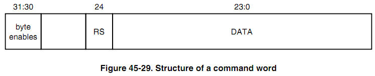
The template memory contains 256 template words. Each template word is a 42 bits words. Accessing a template word require 2 accesses (32bit each).
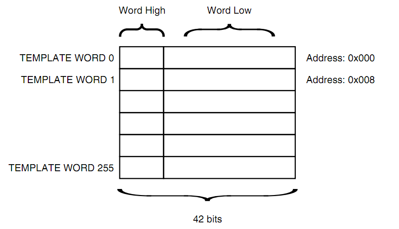
STOP:bit41
OPCODE:bit40~32
OPERAND
MAPPING:The MAPPING field holds a pointer to a register holding 3 fields
WAVEFORM
GLUELOGIC:clock mode or CS mode setting。
SYNC
-
Display controls' generator
This unit generates the control signals associated with the data that are sent to the DI block.
Bus Mapping Unit:
Microcode processing unit
This units arbitrates between the DIs. The priority is hard coded. The priority order is
Sync flow, ARM platform access, IDMAC's Async flows.
45.4.7.2.3 Source arbiter
Once the source of the request to be served was selected and the target DI was chosen, this unit routes the request and all the signals, associated with it, to the correct triple buffer and to the correct source of the data.
代码描述断:
struct fb_videomode {
const char *name; /* optional */
u32 refresh; /* optional */
u32 xres;
u32 yres;
u32 pixclock;
u32 left_margin;
u32 right_margin;
u32 upper_margin;
u32 lower_margin;
u32 hsync_len;
u32 vsync_len;
u32 sync;
u32 vmode;
u32 flag;
};


 5656
5656

 被折叠的 条评论
为什么被折叠?
被折叠的 条评论
为什么被折叠?
 到【灌水乐园】发言


