PCIe 规范核心知识线介绍

-1,PCIe specification

官网下载需要注册该集团的企业id,

Specifications | PCI-SIG

7.0已经出来了,下面 update 到从6.0

PCI Express® Base Specification Revision 6.0


base 6.0
https://pan.baidu.com/s/1kUrho2M7hRJeCNXSxwLN8A?pwd=7zkx

pwd=7zkx


base 5.0
https://pan.baidu.com/s/1aqRrbmR7dNO3gHz3Q3kF0Q

提取码:62b8


4.0
http://pan.baidu.com/s/1dFxqX9Z


3.0
链接:https://pan.baidu.com/s/1lydqD_SiS54bq7Zyz9VsCA 

提取码:evpx 


2.0
https://www.intel.com/content/dam/support/us/en/programmable/support-resources/fpga-wiki/asset03/pci-express-base-r2.1.pdf
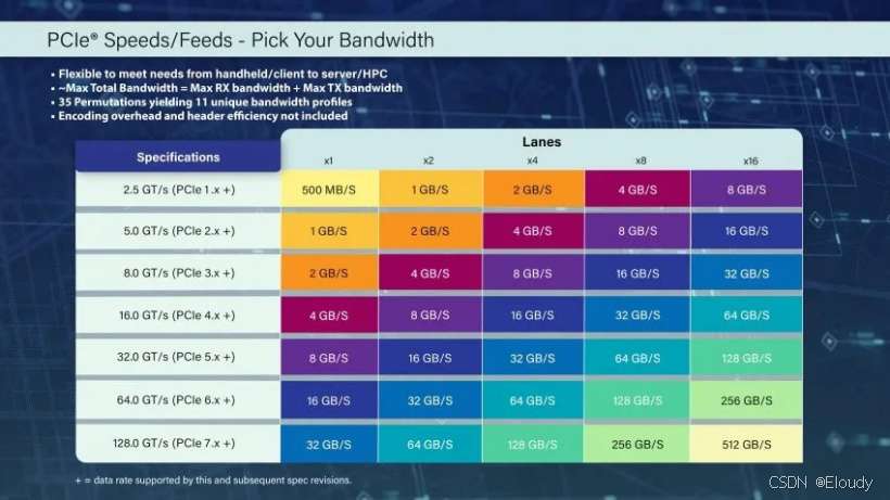
各代带宽:

0,总体Topology

x86 处理器系统中 PCIe的拓扑结构:

PCIe Switch的总体结构

1,PCIe 枚举

BIOS 负责枚举与分派配置设备的 BusID[7:0] : DeviceID[4:0] : FunctionID[2:0];

cpu先识别 Host-PCI-Bridge,其下是Bus0;

在Host-PCI-Bridge 的Bus0下会链接几个固定的 Virtual P2P 节点,CPU出厂前就定义完了,融合在 CPU 的 RootComplex中,类似集成了几个以前的pci桥。

第一个 Virtual下边是Bus1,Bus1下可以链接一个EP或者也给PCIe-SWITCH,内含多个 Virtual P2P,每个P2P都可以延伸出一条 Bus,每个Bus下面要么挂一个EP,要么挂一个PCIe-SWITH,l来衍生出更多Bus。

cpu通过挨家挨户虚拟敲门的方式来探测BUS和其下之设备或总线的存在的可能性。

探测存在后,cpu在根据策略来分配 BUS-id,Device-id,Function-id等,通过配置事务传递对应的PCIe实体,它们会记住自己的id。

这是一个深度优先的过程。

下边是一个分配好配置信息的Xilin的FPGA板卡的信息,使用TeleScanPE软件在Linux上采集了内核的相关的PCIe信息。

2,PCIe 设备 Type0 配置空间

作用:用于EP的描述,每个PCIe的设备的每个Function包含一个Type0的配置空间。

读了Type0的值之后,便可以知道这个设备的功能的类属:网卡,显卡,声卡,。。。这由PCI-SIG来分类定义,参考规范:

《PCI Local Bus Specification Revision 3.0》

《PCI Code and ID Assignment Specification》

必须由RC来读写 Function的 Type0的寄存器。

其配置寄存器信息如下,每个Function 对应一张这样的寄存器        空间表:

还有256 Bytes 之后的扩展配置空间,可以加入一些产品个性化的配置信息:

Traditional multi-drop, parallel bus technology is approaching its practical performance limits. It is clear that balancing system performance requires I/O bandwidth to scale with processing and application demands. There is an industry mandate to re-engineer I/O connectivity within cost constraints. PCI Express comprehends the many I/O requirements presented across the spectrum of computing and communications platforms, and rolls them into a common scalable and extensible I/O industry specification. Alongside these increasing performance demands, the enterprise server and communications markets have the need for improved reliability, security, and quality of service guarantees. This specification will therefore be applicable to multiple market segments. Technology advances in high-speed, point-to-point interconnects enable us to break away from the bandwidth limitations of multi-drop, parallel buses. The PCI Express basic physical layer consists of a differential transmit pair and a differential receive pair. Dual simplex data on these point-to-point connections is self-clocked and its bandwidth increases linearly with interconnect width and frequency. PCI Express takes an additional step of including a message space within its bus protocol that is used to implement legacy “side- band” signals. This further reduction of signal pins produces a very low pin count connection for components and adapters. The PCI Express Transaction, Data Link, and Physical Layers are optimized for chip-to-chip and board-to-board interconnect applications. An inherent limitation of today’s PCI-based platforms is the lack of support for isochronous data delivery, an attribute that is especially important to streaming media applications. To enable these emerging applications, PCI Express adds a virtual channel mechanism. In addition to use for support of isochronous traffic, the virtual channel mechanism provides an infrastructure for future extensions in supporting new applications. By adhering to the PCI Software Model, today’s applications are easily migrated even as emerging applications are enabled.
OBJECTIVE OF THE SPECIFICATION.................................................................................... 27 DOCUMENT ORGANIZATION ................................................................................................ 27 DOCUMENTATION CONVENTIONS...................................................................................... 28 TERMS AND ACRONYMS........................................................................................................ 29 REFERENCE DOCUMENTS...................................................................................................... 36 1. INTRODUCTION ................................................................................................................ 37 1.1. A THIRD GENERATION I/O INTERCONNECT ................................................................... 37 1.2. PCI EXPRESS LINK......................................................................................................... 39 1.3. PCI EXPRESS FABRIC TOPOLOGY .................................................................................. 41 1.3.1. Root Complex........................................................................................................ 41 1.3.2. Endpoints .............................................................................................................. 42 1.3.3. Switch.................................................................................................................... 45 1.3.4. Root Complex Event Collector.............................................................................. 46 1.3.5. PCI Express to PCI/PCI-X Bridge........................................................................ 46 1.4. PCI EXPRESS FABRIC TOPOLOGY CONFIGURATION....................................................... 46 1.5. PCI EXPRESS LAYERING OVERVIEW.............................................................................. 47 1.5.1. Transaction Layer................................................................................................. 48 1.5.2. Data Link Layer .................................................................................................... 48 1.5.3. Physical Layer ...................................................................................................... 49 1.5.4. Layer Functions and Services............................................................................... 49 2. TRANSACTION LAYER SPECIFICATION ..................................................................... 53 2.1. TRANSACTION LAYER OVERVIEW.................................................................................. 53 2.1.1. Address Spaces, Transaction Types, and Usage................................................... 54 2.1.2. Packet Format Overview ...................................................................................... 56 2.2. TRANSACTION LAYER PROTOCOL - PACKET DEFINITION............................................... 58 2.2.1. Common Packet Header Fields ............................................................................ 58 2.2.2. TLPs with Data Payloads - Rules ......................................................................... 61 2.2.3. TLP Digest Rules .................................................................................................. 65 2.2.4. Routing and Addressing Rules .............................................................................. 65 2.2.5. First/Last DW Byte Enables Rules........................................................................ 69 2.2.6. Transaction Descriptor......................................................................................... 71 2.2.7. Memory, I/O, and Configuration Request Rules................................................... 77 2.2.8. Message Request Rules......................................................................................... 83 2.2.9. Completion Rules.................................................................................................. 97 2.2.10. TLP Prefix Rules ................................................................................................. 100 2.3. HANDLING OF RECEIVED TLPS.................................................................................... 104
评论
添加红包

请填写红包祝福语或标题

红包个数最小为10个

红包金额最低5元

当前余额3.43前往充值 >
需支付:10.00
成就一亿技术人!
领取后你会自动成为博主和红包主的粉丝 规则
hope_wisdom
发出的红包
实付
使用余额支付
点击重新获取
扫码支付
钱包余额 0

抵扣说明:

1.余额是钱包充值的虚拟货币,按照1:1的比例进行支付金额的抵扣。
2.余额无法直接购买下载,可以购买VIP、付费专栏及课程。

余额充值