


主要借鉴了米联客的dma传输方案。
纯菜狗,代码和设计中有很多冗余操作,突出一个勉强实现,不会优化,记录一下学习过程,大佬见谅。
Block Design

模块配置和作用分析:
主要根据自己的需要配置。
1.负责输入1k和10k的正弦信号作为测试信号,每1024个64bit数据输出一个last信号2。
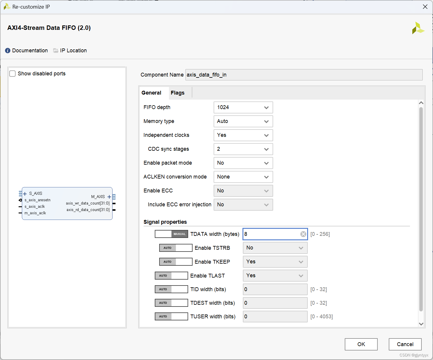
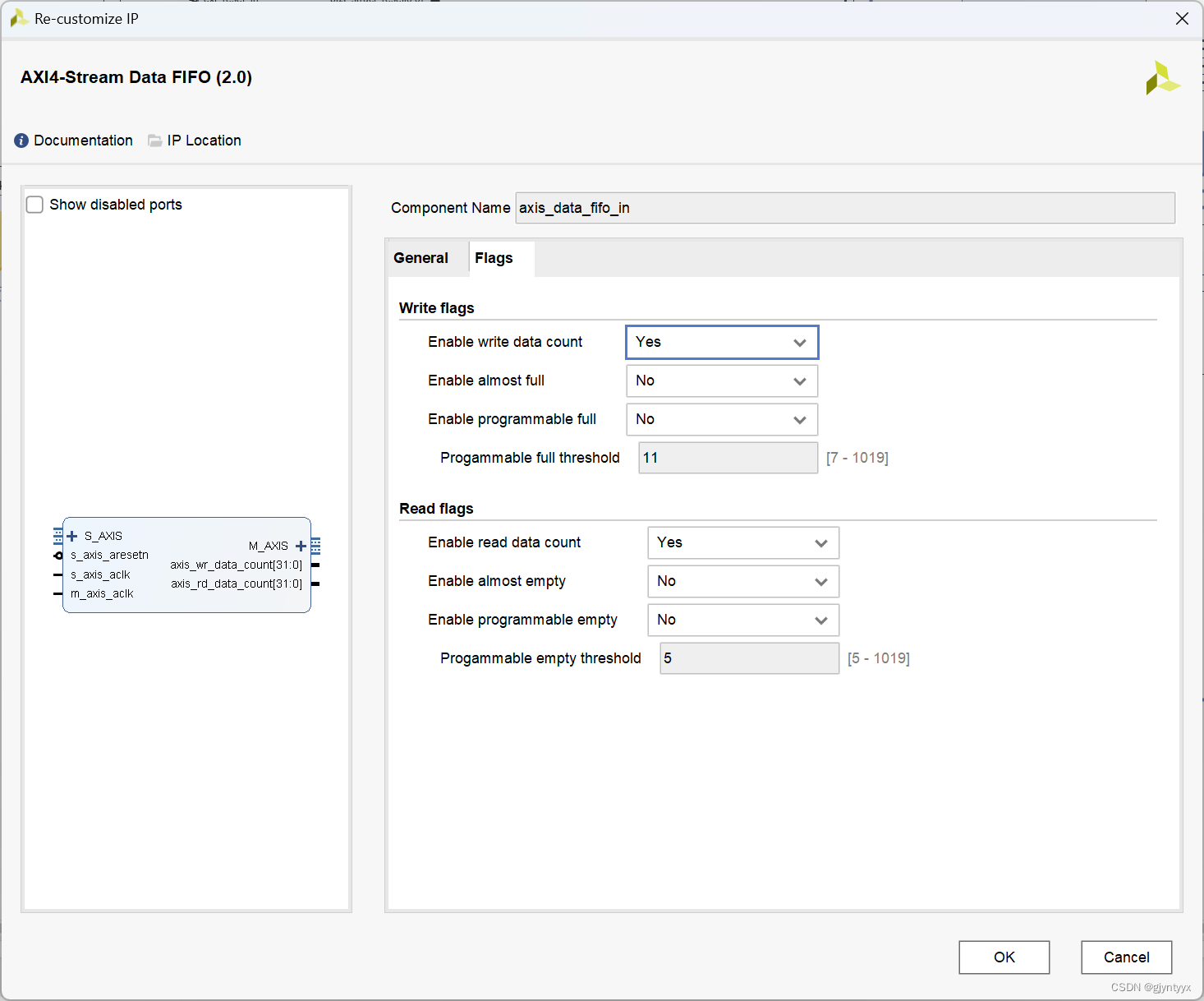
2.fifo_in,负责不同时钟域的数据传输,由40M变为120M,每积累1024个数据就进行一次传输。
3.dma负责数据在PS和PL之间的传输。

4.fifo_out,同2,配置稍微改改。
5.音频数据输出,自己写的rtl代码
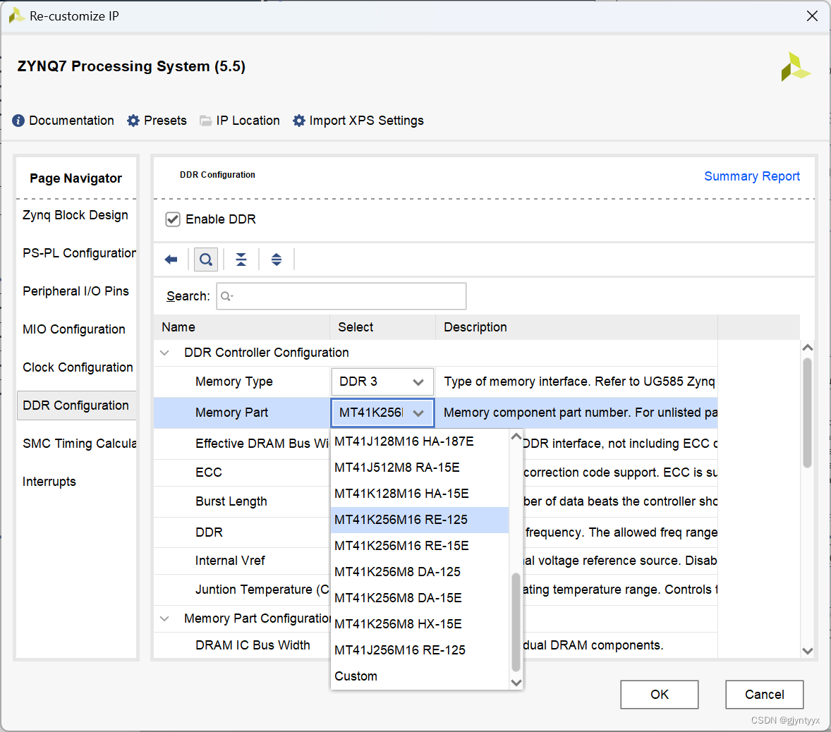
6.PS端。
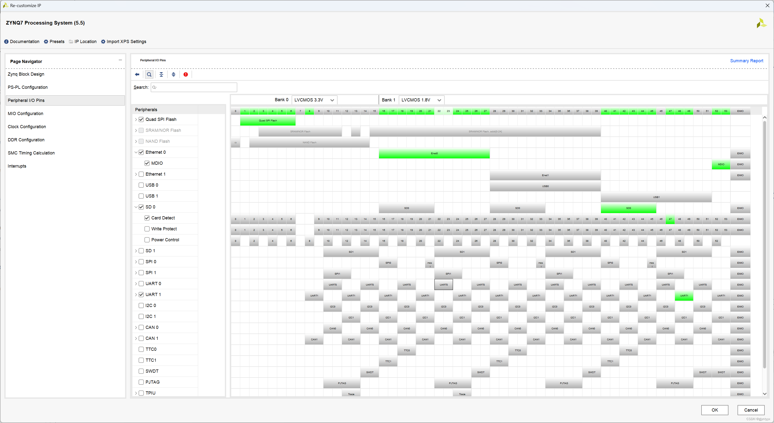
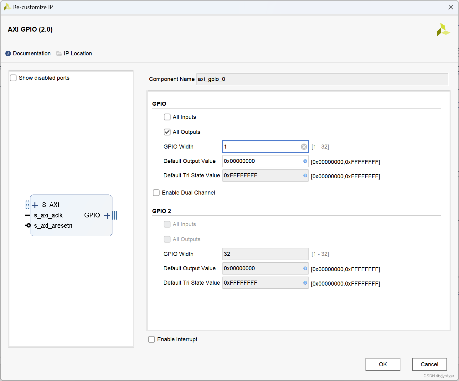
7.gpio接口,负责使能1数据输入模块
VITIS代码编写
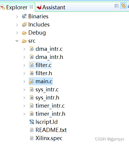
主要代码借鉴了米联客zynq裸机篇2019版第22章
主要添加了filter模块进行滤波操作,并对main.c文件进行了部分修改,删去了计时测速功能,filter模块放在下一篇说。
main.c
/*
*
* www.osrc.cn
* copyright by liyang mi lian dian zi www.osrc.cn
* axi dma test
*
*/
//mrd -bin -file input.bin 0x10300000 2048
#include "dma_intr.h"
#include "timer_intr.h"
#include "sys_intr.h"
#include "xgpio.h"
#include "filter.h"
extern double filterDirectI_singlejoint(double DataIn, double *a, double *b, double *xDelay,double *yDelay ,int numjoint);
//extern double filterDirectI_multjoint(double DataIn, double **a, double **b, double *xDelay,double *yDelay, int numStages);
//extern double filter_single(const double* x, double* y, int xlen, double* a, double* b, int nfilt);
static XScuGic Intc; //GIC
static XAxiDma AxiDma;
static XScuTimer Timer;//timer
volatile u32 RX_ready=1;
volatile u32 TX_ready=1;
int i;
u32 RxBuffer[1024];
u8 *TxBufferPtr= (u8 *)TX_BUFFER_BASE;
u8 *RxBufferPtr=(u8 *)RX_BUFFER_BASE;
u8 *RxBufferPtr2 = (u8 *)RX_BUFFER2_BASE;
u8 *TxBufferPtr2 = (u8 *)TX_BUFFER2_BASE;
//u8 *buffer_temp=(u8 *)BUFFER_TEMP;
u8 Value=0;
double speed_tx;
double speed_rx;
static XGpio Gpio;
#define AXI_GPIO_DEV_ID XPAR_AXI_GPIO_0_BASEADDR
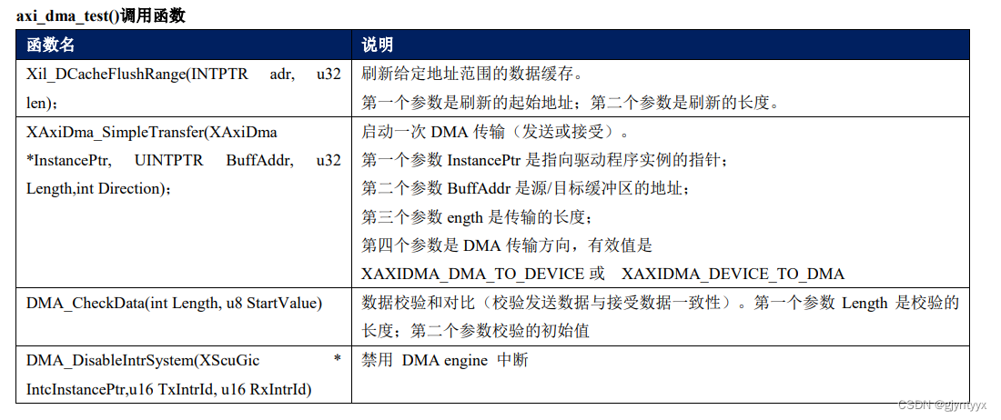
int axi_dma_test()
{
int Status;
TxDone = 0;
RxDone = 0;
Error = 0;
int cnt; //计数0-1
cnt = 0;
while(1)//无限循环一直传输
{
//RX DMA Transfer
if(RX_ready)
{
RX_ready=0;
if(cnt){ //进行乒乓缓存,奇数帧和偶数帧存入不同地址,防止滤波操作延时对缓存数据的影响
Status = XAxiDma_SimpleTransfer(&AxiDma,(u32)(RxBufferPtr2),
(u32)(MAX_PKT_LEN), XAXIDMA_DEVICE_TO_DMA);
}
else
Status = XAxiDma_SimpleTransfer(&AxiDma,(u32)(RxBufferPtr),
(u32)(MAX_PKT_LEN), XAXIDMA_DEVICE_TO_DMA);
if (Status != XST_SUCCESS) {return XST_FAILURE;}
}
if(RxDone)
{
// Xil_DCacheInvalidateRange((u32)RxBufferPtr, MAX_PKT_LEN);
// xil_printf("Rx1=%ld,Rxn=%ld\r\n",*((u32*)RxBufferPtr),*((u32*)(RxBufferPtr+1023*8)) );
RxDone=0;
RX_ready=1;
if(cnt){
filter_all((double*) (RxBufferPtr2), (double*) (TxBufferPtr2));
}
else{
filter_all((double*) (RxBufferPtr), (double*) (TxBufferPtr));
}
}
//TX DMA Transfer
if(TX_ready)
{
TX_ready=0;
if(cnt){
Status = XAxiDma_SimpleTransfer(&AxiDma,(u32)(TxBufferPtr2),
(u32)(MAX_PKT_LEN), XAXIDMA_DEVICE_TO_DMA);
cnt = 0;
}
else{
Status = XAxiDma_SimpleTransfer(&AxiDma,(u32)(TxBufferPtr),
(u32)(MAX_PKT_LEN), XAXIDMA_DEVICE_TO_DMA);
cnt = 1;
}
if (Status != XST_SUCCESS) {return XST_FAILURE;}
}
if(TxDone)
{
TxDone=0;
TX_ready=1;
}
if (Error) {
xil_printf("Failed test transmit%s done, "
"receive%s done\r\n", TxDone? "":" not",
RxDone? "":" not");
goto Done;
}
}
/* Disable TX and RX Ring interrupts and return success */
DMA_DisableIntrSystem(&Intc, TX_INTR_ID, RX_INTR_ID);
Done:
xil_printf("--- Exiting Test --- \r\n");
return XST_SUCCESS;
}
int init_intr_sys(void)
{
DMA_Intr_Init(&AxiDma,0);//initial interrupt system
Init_Intr_System(&Intc); // initial DMA interrupt system
Setup_Intr_Exception(&Intc);
DMA_Setup_Intr_System(&Intc,&AxiDma,TX_INTR_ID,RX_INTR_ID);//setup dma interrpt system
DMA_Intr_Enable(&Intc,&AxiDma);
}
int main(void)
{
int data_len = 1024;
double PI = 3.1415926;
double fs = 31250;
int numjoint = 13;
int i,frame;
frame = 0;
double datain[data_len];
double dataout[data_len];
// while(1) //滤波器代码简单测试
// {
// frame++;
// for (i = 0; i < data_len; ++i)
// {
// datain[i] = 0.5 * (sin(2 * PI * 20 * (frame*data_len + i) / fs) + cos(2 * PI * 10000 * (frame*data_len + i) / fs + PI / 4));
// }
//
filter_single_use(datain, dataout);
// filter_all(datain, dataout);
// }
//mrd -bin -file output.bin 0x00111a48 2048
//mrd -bin -file input.bin 0x00113a48 2048
XGpio_Initialize(&Gpio, AXI_GPIO_DEV_ID);
XGpio_SetDataDirection(&Gpio, 1, 0);
init_intr_sys();
XGpio_DiscreteWrite(&Gpio, 1, 1);
axi_dma_test();
}

axi_dma_test();中的cnt主要是为了实现乒乓缓存,防止滤波处理延迟导致数据还未发送就被新数据覆盖,如果速度仍不够可以采用三级缓存。
dma_intr.h
/*
*
* www.osrc.cn
* www.milinker.com
* copyright by nan jin mi lian dian zi www.osrc.cn
*/
#ifndef DMA_INTR_H
#define DMA_INTR_H
#include "xaxidma.h"
#include "xparameters.h"
#include "xil_exception.h"
#include "xdebug.h"
#include "xscugic.h"
/************************** Constant Definitions *****************************/
/*
* Device hardware build related constants.
*/
#define DMA_DEV_ID XPAR_AXIDMA_0_DEVICE_ID
#define MEM_BASE_ADDR 0x10000000
#define RX_INTR_ID XPAR_FABRIC_AXI_DMA_0_S2MM_INTROUT_INTR
#define TX_INTR_ID XPAR_FABRIC_AXI_DMA_0_MM2S_INTROUT_INTR
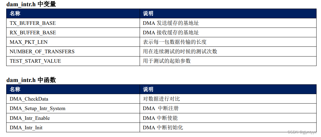
#define TX_BUFFER_BASE (MEM_BASE_ADDR + 0x00100000) //乒乓缓存地址1/2
#define TX_BUFFER2_BASE (MEM_BASE_ADDR + 0x00200000)
#define RX_BUFFER2_BASE (MEM_BASE_ADDR + 0x00400000)
#define RX_BUFFER_BASE (MEM_BASE_ADDR + 0x00300000)
#define RX_BUFFER_HIGH (MEM_BASE_ADDR + 0x004FFFFF)
/* Timeout loop counter for reset
*/
#define RESET_TIMEOUT_COUNTER 10000
/* test start value
*/
#define TEST_START_VALUE 0xC
/*
* Buffer and Buffer Descriptor related constant definition
*/
#define MAX_PKT_LEN 8196 //单位为字节,输入1024个64bit数据 = 1024*64/8
/*
* transfer times
*/
#define NUMBER_OF_TRANSFERS 100000
extern volatile int TxDone;
extern volatile int RxDone;
extern volatile int Error;
int DMA_CheckData(int Length, u8 StartValue);
int DMA_Setup_Intr_System(XScuGic * IntcInstancePtr,XAxiDma * AxiDmaPtr, u16 TxIntrId, u16 RxIntrId);
int DMA_Intr_Enable(XScuGic * IntcInstancePtr,XAxiDma *DMAPtr);
int DMA_Intr_Init(XAxiDma *DMAPtr,u32 DeviceId);
#endif
dma_intr.c
XAxiDma *AxiDmaInst = (XAxiDma *)Callback;这句代码是为了获取当前中断的对象。void *Callback 是一个无符号的指针,传递进来的阐述可以强制转换成其他任何的对象,这里就是强制转换成 XAxiDma 对象了。 IrqStatus =XAxiDma_IntrGetIrq(AxiDmaInst, XAXIDMA_DMA_TO_DEVICE)这个函数获取当前中断号。 XAxiDma_IntrAckIrq(AxiDmaInst, IrqStatus, XAXIDMA_DMA_TO_DEVICE);这个函数是响应当前中断, 通知CPU 当前中断已经被接收,并且清除中断标志位。如果中断全部正确,TxDone将被置为1表示发送中断完成。 如果有错误,则复位DMA,并且设置超时参数.
接收中断函数的原理和发送一样 XAxiDma *AxiDmaInst = (XAxiDma *)Callback;这句代码是为了获取当前中断的对象。void *Callback 是一个无符号的指针,传递进来的阐述可以强制转换成其他任何的对象,这里就是强制转换成 XAxiDma 对象了。 IrqStatus = XAxiDma_IntrGetIrq(AxiDmaInst, XAXIDMA_DEVICE_TO_DMA);这个函数是获取当前中断号。 XAxiDma_IntrAckIrq(AxiDmaInst, IrqStatus, XAXIDMA_DEVICE_TO_DMA);这个函数是响应当前中 断,通知CPU 当前中断已经被接收,并且清除中断标志位。 如果中断全部正确,RxDone将被置为1表示接收中断完成。如果有错误,则复位DMA,并且设置超时参数
/*
 *
 * www.osrc.cn
 * www.milinker.com
 * copyright by nan jin mi lian dian zi www.osrc.cn
*/
#include "dma_intr.h"

volatile int TxDone;
volatile int RxDone;
volatile int Error;
/*****************************************************************************/
/*
*
* This function checks data buffer after the DMA transfer is finished.
*
* We use the static tx/rx buffers.
*
* @param	Length is the length to check
* @param	StartValue is the starting value of the first byte
*
* @return
*		- XST_SUCCESS if validation is successful
*		- XST_FAILURE if validation is failure.
*
* @note		None.
*
******************************************************************************/
 int DMA_CheckData(int Length, u8 StartValue)
{
	u8 *RxPacket;
	int Index = 0;
	u8 Value;

	RxPacket = (u8 *) RX_BUFFER_BASE;
	Value = StartValue;

	/* Invalidate the DestBuffer before receiving the data, in case the
	 * Data Cache is enabled
	 */
#ifndef __aarch64__
	Xil_DCacheInvalidateRange((u32)RxPacket, Length);
#endif

	for(Index = 0; Index < Length; Index++) {
		if (RxPacket[Index] != Value) {
			xil_printf("Data error %d: %x/%x\r\n",
			    Index, RxPacket[Index], Value);

			return XST_FAILURE;
		}
		Value = (Value + 1) & 0xFF;
	}

	return XST_SUCCESS;
}
/*****************************************************************************/
/**
*
* This function disables the interrupts for DMA engine.
*
* @param	IntcInstancePtr is the pointer to the INTC component instance
* @param	TxIntrId is interrupt ID associated w/ DMA TX channel
* @param	RxIntrId is interrupt ID associated w/ DMA RX channel
*
* @return	None.
*
* @note		None.
*
******************************************************************************/
 void DMA_DisableIntrSystem(XScuGic * IntcInstancePtr,
					u16 TxIntrId, u16 RxIntrId)
{
#ifdef XPAR_INTC_0_DEVICE_ID
	/* Disconnect the interrupts for the DMA TX and RX channels */
	XIntc_Disconnect(IntcInstancePtr, TxIntrId);
	XIntc_Disconnect(IntcInstancePtr, RxIntrId);
#else
	XScuGic_Disconnect(IntcInstancePtr, TxIntrId);
	XScuGic_Disconnect(IntcInstancePtr, RxIntrId);
#endif
}
/*****************************************************************************/
/*
*
* This is the DMA TX Interrupt handler function.
*
* It gets the interrupt status from the hardware, acknowledges it, and if any
* error happens, it resets the hardware. Otherwise, if a completion interrupt
* is present, then sets the TxDone.flag
*
* @param	Callback is a pointer to TX channel of the DMA engine.
*
* @return	None.
*
* @note		None.
*
******************************************************************************/
static void DMA_TxIntrHandler(void *Callback)
{

	u32 IrqStatus;
	int TimeOut;
	XAxiDma *AxiDmaInst = (XAxiDma *)Callback;

	/* Read pending interrupts */
	IrqStatus = XAxiDma_IntrGetIrq(AxiDmaInst, XAXIDMA_DMA_TO_DEVICE);

	/* Acknowledge pending interrupts */


	XAxiDma_IntrAckIrq(AxiDmaInst, IrqStatus, XAXIDMA_DMA_TO_DEVICE);

	/*
	 * If no interrupt is asserted, we do not do anything
	 */
	if (!(IrqStatus & XAXIDMA_IRQ_ALL_MASK)) {

		return;
	}

	/*
	 * If error interrupt is asserted, raise error flag, reset the
	 * hardware to recover from the error, and return with no further
	 * processing.
	 */
	if ((IrqStatus & XAXIDMA_IRQ_ERROR_MASK)) {

		Error = 1;

		/*
		 * Reset should never fail for transmit channel
		 */
		XAxiDma_Reset(AxiDmaInst);

		TimeOut = RESET_TIMEOUT_COUNTER;

		while (TimeOut) {
			if (XAxiDma_ResetIsDone(AxiDmaInst)) {
				break;
			}

			TimeOut -= 1;
		}

		return;
	}

	/*
	 * If Completion interrupt is asserted, then set the TxDone flag
	 */
	if ((IrqStatus & XAXIDMA_IRQ_IOC_MASK)) {

		TxDone = 1;
	}
}

/*****************************************************************************/
/*
*
* This is the DMA RX interrupt handler function
*
* It gets the interrupt status from the hardware, acknowledges it, and if any
* error happens, it resets the hardware. Otherwise, if a completion interrupt
* is present, then it sets the RxDone flag.
*
* @param	Callback is a pointer to RX channel of the DMA engine.
*
* @return	None.
*
* @note		None.
*
******************************************************************************/
static void DMA_RxIntrHandler(void *Callback)
{
	u32 IrqStatus;
	int TimeOut;
	XAxiDma *AxiDmaInst = (XAxiDma *)Callback;

	/* Read pending interrupts */
	IrqStatus = XAxiDma_IntrGetIrq(AxiDmaInst, XAXIDMA_DEVICE_TO_DMA);

	/* Acknowledge pending interrupts */
	XAxiDma_IntrAckIrq(AxiDmaInst, IrqStatus, XAXIDMA_DEVICE_TO_DMA);

	/*
	 * If no interrupt is asserted, we do not do anything
	 */
	if (!(IrqStatus & XAXIDMA_IRQ_ALL_MASK)) {
		return;
	}

	/*
	 * If error interrupt is asserted, raise error flag, reset the
	 * hardware to recover from the error, and return with no further
	 * processing.
	 */
	if ((IrqStatus & XAXIDMA_IRQ_ERROR_MASK)) {

		Error = 1;

		/* Reset could fail and hang
		 * NEED a way to handle this or do not call it??
		 */
		XAxiDma_Reset(AxiDmaInst);

		TimeOut = RESET_TIMEOUT_COUNTER;

		while (TimeOut) {
			if(XAxiDma_ResetIsDone(AxiDmaInst)) {
				break;
			}

			TimeOut -= 1;
		}

		return;
	}

	/*
	 * If completion interrupt is asserted, then set RxDone flag
	 */
	if ((IrqStatus & XAXIDMA_IRQ_IOC_MASK)) {

		RxDone = 1;
	}
}

/*****************************************************************************/
/*
*
* This function setups the interrupt system so interrupts can occur for the
* DMA, it assumes INTC component exists in the hardware system.
*
* @param	IntcInstancePtr is a pointer to the instance of the INTC.
* @param	AxiDmaPtr is a pointer to the instance of the DMA engine
* @param	TxIntrId is the TX channel Interrupt ID.
* @param	RxIntrId is the RX channel Interrupt ID.
*
* @return
*		- XST_SUCCESS if successful,
*		- XST_FAILURE.if not succesful
*
* @note		None.
*
******************************************************************************/
int DMA_Setup_Intr_System(XScuGic * IntcInstancePtr,XAxiDma * AxiDmaPtr, u16 TxIntrId, u16 RxIntrId)
{
	int Status;
	XScuGic_SetPriorityTriggerType(IntcInstancePtr, TxIntrId, 0xA0, 0x3);

	XScuGic_SetPriorityTriggerType(IntcInstancePtr, RxIntrId, 0xA0, 0x3);
	/*
	 * Connect the device driver handler that will be called when an
	 * interrupt for the device occurs, the handler defined above performs
	 * the specific interrupt processing for the device.
	 */
	Status = XScuGic_Connect(IntcInstancePtr, TxIntrId,
				(Xil_InterruptHandler)DMA_TxIntrHandler,
				AxiDmaPtr);
	if (Status != XST_SUCCESS) {
		return Status;
	}

	Status = XScuGic_Connect(IntcInstancePtr, RxIntrId,
				(Xil_InterruptHandler)DMA_RxIntrHandler,
				AxiDmaPtr);
	if (Status != XST_SUCCESS) {
		return Status;
	}

	XScuGic_Enable(IntcInstancePtr, TxIntrId);
	XScuGic_Enable(IntcInstancePtr, RxIntrId);
	return XST_SUCCESS;
}


int DMA_Intr_Enable(XScuGic * IntcInstancePtr,XAxiDma *DMAPtr)
{

	/* Disable all interrupts before setup */

	XAxiDma_IntrDisable(DMAPtr, XAXIDMA_IRQ_ALL_MASK,
						XAXIDMA_DMA_TO_DEVICE);

	XAxiDma_IntrDisable(DMAPtr, XAXIDMA_IRQ_ALL_MASK,
				XAXIDMA_DEVICE_TO_DMA);

	/* Enable all interrupts */
	XAxiDma_IntrEnable(DMAPtr, XAXIDMA_IRQ_ALL_MASK,
							XAXIDMA_DMA_TO_DEVICE);

	XAxiDma_IntrEnable(DMAPtr, XAXIDMA_IRQ_ALL_MASK,
							XAXIDMA_DEVICE_TO_DMA);
	return XST_SUCCESS;

}


int DMA_Intr_Init(XAxiDma *DMAPtr,u32 DeviceId)
{
	int Status;
	XAxiDma_Config *Config=NULL;

	Config = XAxiDma_LookupConfig(DeviceId);
	if (!Config) {
		xil_printf("No config found for %d\r\n", DeviceId);
		return XST_FAILURE;
	}

	/* Initialize DMA engine */
	Status = XAxiDma_CfgInitialize(DMAPtr, Config);

	if (Status != XST_SUCCESS) {
		xil_printf("Initialization failed %d\r\n", Status);
		return XST_FAILURE;
	}

	if(XAxiDma_HasSg(DMAPtr)){
		xil_printf("Device configured as SG mode \r\n");
		return XST_FAILURE;
	}
	return XST_SUCCESS;

}
sys_intr.h
sys_intr.c、sys_intr.h 包含了系统中断控制器的驱动程 序。
 /*sys_intr.h
 * Created on: 2016年11月22日
 * www.osrc.cn
 * copyright by liyang mi lian dian zi www.osrc.cn
*/

#ifndef SYS_INTR_H_
#define SYS_INTR_H_

#include "xparameters.h"
#include "xil_exception.h"
#include "xdebug.h"
#include "xscugic.h"


#define INTC_DEVICE_ID          XPAR_SCUGIC_SINGLE_DEVICE_ID

int Init_Intr_System(XScuGic * IntcInstancePtr);
void setup_Intr_Exception(XScuGic * IntcInstancePtr);

#endif /* SYS_INTR_H_ */
sys_intr.c
 /*sys_intr.c
 * Created on: 2016年11月22日
 * www.osrc.cn
 * copyright by liyang mi lian dian zi www.osrc.cn
*/
#include "sys_intr.h"
void Setup_Intr_Exception(XScuGic * IntcInstancePtr)
{
	/* Enable interrupts from the hardware */
	Xil_ExceptionInit();
	Xil_ExceptionRegisterHandler(XIL_EXCEPTION_ID_INT,
			(Xil_ExceptionHandler)XScuGic_InterruptHandler,
			(void *)IntcInstancePtr);

	Xil_ExceptionEnable();
}

int Init_Intr_System(XScuGic * IntcInstancePtr)
{
	int Status;

	XScuGic_Config *IntcConfig;
	/*
	 * Initialize the interrupt controller driver so that it is ready to
	 * use.
	 */
	IntcConfig = XScuGic_LookupConfig(INTC_DEVICE_ID);
	if (NULL == IntcConfig) {
		return XST_FAILURE;
	}

	Status = XScuGic_CfgInitialize(IntcInstancePtr, IntcConfig,
					IntcConfig->CpuBaseAddress);
	if (Status != XST_SUCCESS) {
		return XST_FAILURE;
	}
	return XST_SUCCESS;
}
输入数据时序分析
由于项目中的输入模块是老师直接发给我的,所以相当于半个黑盒子,故采用米联课的输入代码进行输入数据时序的分析。
S_AXIS_tready、S_AXIS_tvalid、S_AXIS_tlast重点关注这三者信号的时序关系。
`timescale 1ns / 1ps
//
// Company:
// Engineer:
//
// Create Date: 2019/05/24 00:27:58
// Design Name:
// Module Name: system_dma_top
// Project Name:
// Target Devices:
// Tool Versions:
// Description:
//
// Dependencies:
//
// Revision:
// Revision 0.01 - File Created
// Additional Comments:
//
//


module system_dma_top(
  inout [14:0]DDR_addr,
  inout [2:0]DDR_ba,
  inout DDR_cas_n,
  inout DDR_ck_n,
  inout DDR_ck_p,
  inout DDR_cke,
  inout DDR_cs_n,
  inout [3:0]DDR_dm,
  inout [31:0]DDR_dq,
  inout [3:0]DDR_dqs_n,
  inout [3:0]DDR_dqs_p,
  inout DDR_odt,
  inout DDR_ras_n,
  inout DDR_reset_n,
  inout DDR_we_n,
  inout FIXED_IO_ddr_vrn,
  inout FIXED_IO_ddr_vrp,
  inout [53:0]FIXED_IO_mio,
  inout FIXED_IO_ps_clk,
  inout FIXED_IO_ps_porb,
  inout FIXED_IO_ps_srstb,
  output i2s_sck_o,
  output i2s_sdata_o,
  output i2s_ws_o
);

  reg [64:0]S_AXIS_tdata;
  reg  S_AXIS_tlast;
  reg S_AXIS_tvalid;
  wire FCLK_CLK0;
  wire s_axis_aclk;
  wire s_axis_aresetn;
  wire [7:0]S_AXIS_tkeep;
  wire S_AXIS_tready;
  wire [0:0]gpio_rtl_tri_o;
  wire [0:0]peripheral_aresetn;
  reg [1:0] state;

assign S_AXIS_tkeep = 8'b11111111;
assign s_axis_aclk =  FCLK_CLK1;
assign s_axis_aresetn = peripheral_aresetn;

always@(posedge FCLK_CLK1)
   begin
       if(!peripheral_aresetn) begin
           S_AXIS_tvalid <= 1'b0;
           S_AXIS_tdata <= 64'd0;
           S_AXIS_tlast <= 1'b0;
           state <=0;
       end
       else begin
          case(state)
            0: begin
                if(gpio_rtl_tri_o&& S_AXIS_tready) begin
                   S_AXIS_tvalid <= 1'b1;
                   state <= 1;
                end
                else begin
                   S_AXIS_tvalid <= 1'b0;
                   state <= 0;
                end
              end
            1:begin
                 if(S_AXIS_tready) begin
                     S_AXIS_tdata <= S_AXIS_tdata + 1'b1;   //非阻塞赋值
                     if(S_AXIS_tdata == 16'd1022) begin
                        S_AXIS_tlast <= 1'b1;
                        state <= 2;
                     end
                     else begin
                        S_AXIS_tlast <= 1'b0;
                        state <= 1;
                     end
                 end
                 else begin
                    S_AXIS_tdata <= S_AXIS_tdata;
                    state <= 1;
                 end
              end
            2:begin
                 if(!S_AXIS_tready) begin
                    S_AXIS_tvalid <= 1'b1;
                    S_AXIS_tlast <= 1'b1;
                    S_AXIS_tdata <= S_AXIS_tdata;
                    state <= 2;
                 end
                 else begin
                    S_AXIS_tvalid <= 1'b0;
                    S_AXIS_tlast <= 1'b0;
                    S_AXIS_tdata <= 64'd0;
                    state <= 0;
                 end
              end
           default: state <=0;
           endcase
       end
   end


  system system_i
       (.DDR_addr(DDR_addr),
        .DDR_ba(DDR_ba),
        .DDR_cas_n(DDR_cas_n),
        .DDR_ck_n(DDR_ck_n),
        .DDR_ck_p(DDR_ck_p),
        .DDR_cke(DDR_cke),
        .DDR_cs_n(DDR_cs_n),
        .DDR_dm(DDR_dm),
        .DDR_dq(DDR_dq),
        .DDR_dqs_n(DDR_dqs_n),
        .DDR_dqs_p(DDR_dqs_p),
        .DDR_odt(DDR_odt),
        .DDR_ras_n(DDR_ras_n),
        .DDR_reset_n(DDR_reset_n),
        .DDR_we_n(DDR_we_n),
        .FCLK_CLK1(FCLK_CLK1),
        .FIXED_IO_ddr_vrn(FIXED_IO_ddr_vrn),
        .FIXED_IO_ddr_vrp(FIXED_IO_ddr_vrp),
        .FIXED_IO_mio(FIXED_IO_mio),
        .FIXED_IO_ps_clk(FIXED_IO_ps_clk),
        .FIXED_IO_ps_porb(FIXED_IO_ps_porb),
        .FIXED_IO_ps_srstb(FIXED_IO_ps_srstb),
        .S_AXIS_tdata(S_AXIS_tdata),
        .S_AXIS_tkeep(S_AXIS_tkeep),
        .S_AXIS_tlast(S_AXIS_tlast),
        .S_AXIS_tready(S_AXIS_tready),
        .S_AXIS_tvalid(S_AXIS_tvalid),
        .gpio_rtl_tri_o(gpio_rtl_tri_o),
        .peripheral_aresetn(peripheral_aresetn),
        .s_axis_aclk(s_axis_aclk),
        .i2s_sck_o(i2s_sck_o),
        .i2s_sdata_o(i2s_sdata_o),
        .i2s_ws_o(i2s_ws_o),
        .s_axis_aresetn(s_axis_aresetn));

endmodule
初始状态
            0: begin
                if(gpio_rtl_tri_o&& S_AXIS_tready) begin
                   S_AXIS_tvalid <= 1'b1;
                   state <= 1;
                end
                else begin
                   S_AXIS_tvalid <= 1'b0;
                   state <= 0;
                end
              end
根据vitis中的代码,gpio信号会在dma传输开始前拉高,当gpio拉高且fifo处于ready状态时,将valid信号拉高,表明数据有效,开始第一帧数据的传输。
传输状态
            1:begin
                 if(S_AXIS_tready) begin
                     S_AXIS_tdata <= S_AXIS_tdata + 1'b1;   //非阻塞赋值
                     if(S_AXIS_tdata == 16'd1022) begin
                        S_AXIS_tlast <= 1'b1;
                        state <= 2;
                     end
                     else begin
                        S_AXIS_tlast <= 1'b0;
                        state <= 1;
                     end
                 end
                 else begin
                    S_AXIS_tdata <= S_AXIS_tdata;
                    state <= 1;
                 end
              end
传输1024个递增的64bit数组,由于采用的是非阻塞赋值,虽然在第1023个数据时,对tlast进行拉高,且state转变为结束状态,但只有在下一时钟周期才会变化,即第1024个数据,进行last拉高和状态转变。
结束状态
            2:begin
                 if(!S_AXIS_tready) begin
                    S_AXIS_tvalid <= 1'b1;
                    S_AXIS_tlast <= 1'b1;
                    S_AXIS_tdata <= S_AXIS_tdata;
                    state <= 2;
                 end
                 else begin
                    S_AXIS_tvalid <= 1'b0;
                    S_AXIS_tlast <= 1'b0;
                    S_AXIS_tdata <= 64'd0;
                    state <= 0;
                 end
              end
结束状态对fifo状态进行判断,如果fifo非满,也就是处于ready状态,拉低last和valid信号,直接进入初始状态进行下一轮传输。如果fifo满,继续保持valid和last信号为高,等待fifo传输完毕。
总结
要输入自己的数据只要满足上述时序就可以,即在传输第一个数据时将valid拉高,在最后一个数据将last拉高,ready信号只和fifo有关,fifo为满时为0,ready为0时,所有传输停止,valid和last信号保持不变;valid持续到该组数据的last信号拉低为止,last信号理论上只持续一个时钟周期(除非last拉高时候ready为低)。


 580
580


 被折叠的 条评论
为什么被折叠?
被折叠的 条评论
为什么被折叠?
 到【灌水乐园】发言


