


 本文介绍了一种使用Verilog在FPGA上处理图像的方法,包括读取位图文件、执行图像处理操作(如反转、对比度调整等)以及将处理后的图像写回到位图文件中。
This project is aimed to show details how to process an image on FPGA using Verilog from reading a bitmap image (.bmp), processing and writing the processed result to an output bitmap image. The Verilog code for image processing is presented.
In this project, some simple processing operations are implemented such as inversion, contrast, brightness and threshold operations. An input .bmp image is processed by a selected operation and then, the processed image is written to a bitmap image output.bmp to see if it is processed correctly.
The operations for processing an input image are defined in the following definition file. To change the processing operation, just switch the comment line.
/************************************************************/
/****************** Definition file *************************/
/************************************************************/
`define INPUTFILENAME "./img/your_image.hex" // Input file name
`define OUTPUTFILENAME "output.bmp" // Output file name
// Choose the operation of code by delete in the beginning of the selected line
//`define BRIGHTNESS_OPERATION
//`define CONTRAST_OPERATION
 `define INVERT_OPERATION
//`define THRESHOLD_OPERATION
The definition file is also to define paths and names of the input and output file.
First of all, to process the .bmp image on FPGA, the image is converted from bitmap to hexadecimal format. Below is a Matlab example code to convert a bitmap image to .hex file. Image size is 768x512 and the hex file includes R, G, B data of the bitmap image.
b=imread('kodim24.bmp'); % 24-bit BMP image RGB888

k=1;
for i=512:-1:1
  for j=1:768
    a(k)=b(i,j,1);
    a(k+1)=b(i,j,2);
    a(k+2)=b(i,j,3);
    k=k+3;
  end
end
fid = fopen('kodim24.hex', 'wt');
fprintf(fid, '%x\n', a);
disp('Text file write done');
disp(' ');
fclose(fid);
Afterer obtaining .hex file from bitmap image, the your_image.hex is copied to ./img folder to be processed. Then, the following Verilog module is used to read the .hex file:
/******************************************************************/
/********** Module for reading and processing image ***************/ /******************************************************************/
`include "parameter.v" // Include definition file
module image_read
#( parameter
    WIDTH = 768, // Image width
    HEIGHT = 512, // Image height
    INFILE = "./img/your_image.hex", // image file
    START_UP_DELAY = 100, //Delay during start up time
    HSYNC_DELAY = 160, // Delay between HSYNC pulses
    VALUE= 100, // value for Brightness operation
    THRESHOLD= 90, // Threshold value for Threshold and contrast operation
    ValueToMul=2,
    ValueToAdd= 10, // Value to add in contrast addition
    ValueToSubtract= 15 , // Value to add in contrast addition
    SIGN=1 // Sign value using for brightness operation
           // SIGN = 0: Brightness subtraction
           // SIGN = 1: Brightness addition
)
(
input HCLK, // clock
input HRESETn, // Reset (active low)
output reg VSYNC, // Vertical synchronous pulse
// This signal is often a way to indicate that one entire image is transmitted.
// Just create and is not used, will be used once a video or many images are ransmitted.
output reg HSYNC,
// Horizontal synchronous pulse
// An HSYNC indicates that one line of the image is transmitted.
//Used to be a horizontal synchronous signals for writing bmp file.
output reg [7:0] DATA_R0, // 8 bit Red data (even)
output reg [7:0] DATA_G0, // 8 bit Green data (even)
output reg [7:0] DATA_B0, // 8 bit Blue data (even)
output reg [7:0] DATA_R1, // 8 bit Red data (odd)
output reg [7:0] DATA_G1, // 8 bit Green data (odd)
output reg [7:0] DATA_B1, // 8 bit Blue data (odd)
output ctrl_done // Done flag
);
//-------------------------------------------------//
// -------- Reading data from input file ----------//
//-------------------------------------------------//
initial begin
  $readmemh(INFILE,total_memory,0,sizeOfLengthReal-1); // read file from INFILE
end
// use 3 intermediate signals RGB to save image data
always@(start) begin
if(start == 1'b1) begin
  for(i=0; i)
  temp_BMP[i] = total_memory[i+0][7:0];
end
for(i=0; i)
  for(j=0; j)
    org_R[WIDTH*i+j] = temp_BMP[WIDTH*3*(HEIGHT-i-1)+3*j+0];
    org_G[WIDTH*i+j] = temp_BMP[WIDTH*3*(HEIGHT-i-1)+3*j+1];
    org_B[WIDTH*i+j] = temp_BMP[WIDTH*3*(HEIGHT-i-1)+3*j+2];
  end
end
end
end
To read the hexadecimal file, $readmemh is used in Verilog. After reading the .hex file, RGB data is saved into memory and processed. Below is the Verilog code to perform inverting operation:
/**************************************/
/********** INVERT_OPERATION **********/
/**************************************/
`ifdef INVERT_OPERATION
value2 =(org_B[WIDTH * row + col ] + org_R[WIDTH * row + col] +org_G[WIDTH * row + col])/2;
value4 =(org_B[WIDTH * row + col ] + org_R[WIDTH * row + col] +org_G[WIDTH * row + col])/4;
value = (value2+value4)/2;
DATA_R0=255-value;
DATA_G0=255-value;
DATA_B0=255-value;
value2 =(org_B[WIDTH * row + col+1] + org_R[WIDTH * row + col+1] +org_G[WIDTH * row + col+1])/2;
value4 =(org_B[WIDTH * row + col+1] + org_R[WIDTH * row + col+1] +org_G[WIDTH * row + col+1])/4;
value = (value2+value4)/2;
DATA_R1=255-value;
DATA_G1=255-value;
DATA_B1=255-value;
`endif
After processed the image, it is needed to write the processed data to an output image. The following Verilog code is to write processed data to a bitmap image:
/****************** Module for writing .bmp image *************/
/**************************************************************/
module image_write #(parameter
WIDTH = 768, // Image width
HEIGHT = 512, // Image height
INFILE = "output.bmp", // Output image
BMP_HEADER_NUM = 54 // Header for bmp image
)
(
input HCLK, // Clock input
HRESETn, // Reset active low
input hsync, // Hsync pulse
input [7:0] DATA_WRITE_R0, // Red 8-bit data (odd)
input [7:0] DATA_WRITE_G0, // Green 8-bit data (odd)
input [7:0] DATA_WRITE_B0, // Blue 8-bit data (odd)
input [7:0] DATA_WRITE_R1, // Red 8-bit data (even)
input [7:0] DATA_WRITE_G1, // Green 8-bit data (even)
input [7:0] DATA_WRITE_B1, // Blue 8-bit data (even)
output reg Write_Done
);
//-----------------------------------//
//-------Header data for bmp image-----//
//-------------------------------------//
// Windows BMP files begin with a 54-byte header:
// Check the website to see the value of this header:
// http://www.fastgraph.com/help/bmp_header_format.html
initial  begin
BMP_header[ 0] = 66;BMP_header[28] =24;
BMP_header[ 1] = 77;BMP_header[29] = 0;
BMP_header[ 2] = 54;BMP_header[30] = 0;
BMP_header[ 3] = 0;BMP_header[31] = 0;
BMP_header[ 4] = 18;BMP_header[32] = 0;
BMP_header[ 5] = 0;BMP_header[33] = 0;
BMP_header[ 6] = 0;BMP_header[34] = 0;
BMP_header[ 7] = 0;BMP_header[35] = 0;
BMP_header[ 8] = 0;BMP_header[36] = 0;
BMP_header[ 9] = 0;BMP_header[37] = 0;
BMP_header[10] = 54;BMP_header[38] = 0;
BMP_header[11] = 0;BMP_header[39] = 0;
BMP_header[12] = 0;BMP_header[40] = 0;
BMP_header[13] = 0;BMP_header[41] = 0;
BMP_header[14] = 40;BMP_header[42] = 0;
BMP_header[15] = 0;BMP_header[43] = 0;
BMP_header[16] = 0;BMP_header[44] = 0;
BMP_header[17] = 0;BMP_header[45] = 0;
BMP_header[18] = 0;BMP_header[46] = 0;
BMP_header[19] = 3;BMP_header[47] = 0;
BMP_header[20] = 0;BMP_header[48] = 0;
BMP_header[21] = 0;BMP_header[49] = 0;
BMP_header[22] = 0;BMP_header[50] = 0;
BMP_header[23] = 2;BMP_header[51] = 0;
BMP_header[24] = 0;BMP_header[52] = 0;
BMP_header[25] = 0;BMP_header[53] = 0;
BMP_header[26] = 1; BMP_header[27] = 0;
end
//---------------------------------------------//
//--------------Write .bmp file ---------------//
//---------------------------------------------//
initial
begin
  fd = $fopen(INFILE, "wb+");
end
 always@(Write_Done) begin
// once the processing was done, bmp image will be created if(Write_Done == 1'b1) begin
for(i=0; i
begin
 $fwrite(fd, "%c", BMP_header[i][7:0]); // write the header end for(i=0; i
begin
// write R0B0G0 and R1B1G1 (6 bytes) in a loop
$fwrite(fd, "%c", out_BMP[i ][7:0]);
$fwrite(fd, "%c", out_BMP[i+1][7:0]);
$fwrite(fd, "%c", out_BMP[i+2][7:0]);
$fwrite(fd, "%c", out_BMP[i+3][7:0]);
$fwrite(fd, "%c", out_BMP[i+4][7:0]);
$fwrite(fd, "%c", out_BMP[i+5][7:0]);
end
end
end
The header data for bitmap image is very important and it is published here. If there is no header data, the written image could not be correctly displayed. In Verilog HDL, $fwrite command is used to write data to file.
Here we go, now writing testbench to verify the code:
`timescale 1ns/1ps
/**************************************************/
/******* Testbench for simulation *****************/ /********************************************8*****/
`include "parameter.v"
// include definition file module tb_simulation;
//-------------------------------------------------
// Internal Signals
//-------------------------------------------------
reg HCLK, HRESETn;
wire vsync;
wire hsync;
wire [ 7 : 0] data_R0;
wire [ 7 : 0] data_G0;
wire [ 7 : 0] data_B0;
wire [ 7 : 0] data_R1;
wire [ 7 : 0] data_G1;
wire [ 7 : 0] data_B1;
wire enc_done;
image_read #(.INFILE(`INPUTFILENAME))
u_image_read (
 .HCLK (HCLK ),
 .HRESETn (HRESETn ),
 .VSYNC (vsync ),
 .HSYNC (hsync ),
 .DATA_R0 (data_R0 ),
 .DATA_G0 (data_G0 ),
 .DATA_B0 (data_B0 ),
 .DATA_R1 (data_R1 ),
 .DATA_G1 (data_G1 ),
 .DATA_B1 (data_B1 ),
 .ctrl_done (enc_done)
);
image_write #(.INFILE(`OUTPUTFILENAME))
u_image_write (
 .HCLK(HCLK),
 .HRESETn(HRESETn),
 .hsync(hsync),
 .DATA_WRITE_R0(data_R0),
 .DATA_WRITE_G0(data_G0),
 .DATA_WRITE_B0(data_B0),
 .DATA_WRITE_R1(data_R1),
 .DATA_WRITE_G1(data_G1),
 .DATA_WRITE_B1(data_B1),
 .Write_Done()
 );
//-------------------------------------
// Test Vectors
//-------------------------------------
initial
begin
  HCLK = 0;
  forever #10
    HCLK = ~HCLK;
end
initial
begin
  HRESETn = 0;
  #25 HRESETn = 1;
end
endmodule
Now, we have everything to run simulation to verify the code. Let me pick the following image as the input bitmap file:
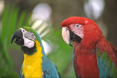
Input bitmap image
And this is the output image being processed by the operations:
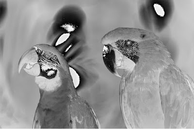
Output bitmap image after inverting
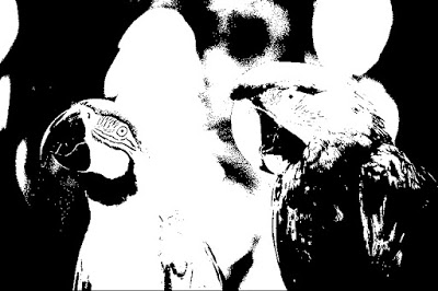
Output bitmap image after threshold operation
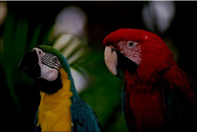
Output bitmap image after subtracting brightness


 5527
5527

 被折叠的 条评论
为什么被折叠?
被折叠的 条评论
为什么被折叠?
 到【灌水乐园】发言


