


(未完待续,持续更新中....)
目录
1 中断控制器
1.1 PIC
PIC,Programmable Interrupt Controller,即8259,可参考资料:
8259 PIC - OSDev Wikihttps://wiki.osdev.org/8259_PIC8259A PROGRAMMABLE INTERRUPT CONTROLLERhttps://pdos.csail.mit.edu/6.828/2017/readings/hardware/8259A.pdf通常将两块8259A如下图连接起来:

Each of the two 8259 PICs in modern systems have 8 inputs. When any of the inputs is raised, the PIC sets a bit internally telling one of the inputs needs servicing. It then checks whether that channel is masked or not, and whether there's an interrupt already pending. If the channel is unmasked and there's no interrupt pending, the PIC will raise the interrupt line. On the slave, this feeds IRQ 2 to the master, and the master is connected to the processor interrupt line.
When the processor accepts the interrupt, the master checks which of the two PICs is responsible for answering, then either supplies the interrupt number to the processor, or asks the slave to do so. The PIC that answers looks up the "vector offset" variable stored internally and adds the input line to form the requested interrupt number. After that the processor will look up the interrupt address and act accordingly (see Interrupts for more details).
上文中提到的vector offset,通过IO Port配置进去的,具体方法列出的链接中,参考PCI_remap(),
/* reinitialize the PIC controllers, giving them specified vector offsets
   rather than 8h and 70h, as configured by default */

#define ICW1_ICW4	0x01		/* ICW4 (not) needed */
#define ICW1_SINGLE	0x02		/* Single (cascade) mode */
#define ICW1_INTERVAL4	0x04		/* Call address interval 4 (8) */
#define ICW1_LEVEL	0x08		/* Level triggered (edge) mode */
#define ICW1_INIT	0x10		/* Initialization - required! */

#define ICW4_8086	0x01		/* 8086/88 (MCS-80/85) mode */
#define ICW4_AUTO	0x02		/* Auto (normal) EOI */
#define ICW4_BUF_SLAVE	0x08		/* Buffered mode/slave */
#define ICW4_BUF_MASTER	0x0C		/* Buffered mode/master */
#define ICW4_SFNM	0x10		/* Special fully nested (not) */

/*
arguments:
	offset1 - vector offset for master PIC
		vectors on the master become offset1..offset1+7
	offset2 - same for slave PIC: offset2..offset2+7
*/
void PIC_remap(int offset1, int offset2)
{
	unsigned char a1, a2;

	a1 = inb(PIC1_DATA);                        // save masks
	a2 = inb(PIC2_DATA);

	outb(PIC1_COMMAND, ICW1_INIT | ICW1_ICW4);  // starts the initialization sequence (in cascade mode)
	io_wait();
	outb(PIC2_COMMAND, ICW1_INIT | ICW1_ICW4);
	io_wait();
	outb(PIC1_DATA, offset1);                 // ICW2: Master PIC vector offset
	io_wait();
	outb(PIC2_DATA, offset2);                 // ICW2: Slave PIC vector offset
	io_wait();
	outb(PIC1_DATA, 4);                       // ICW3: tell Master PIC that there is a slave PIC at IRQ2 (0000 0100)
	io_wait();
	outb(PIC2_DATA, 2);                       // ICW3: tell Slave PIC its cascade identity (0000 0010)
	io_wait();

	outb(PIC1_DATA, ICW4_8086);
	io_wait();
	outb(PIC2_DATA, ICW4_8086);
	io_wait();

	outb(PIC1_DATA, a1);   // restore saved masks.
	outb(PIC2_DATA, a2);
}
经过PCI_remap(),Master PIC的各个引脚对应的vector分别是offset1 ... offset + 7
综上,PIC的工作方式,大致上分为三步:
- 外设在某条irq line上输出;
- PIC通知CPU
- CPU从PIC获取中断的vector,然后调用IDT中对应vector的处理函数
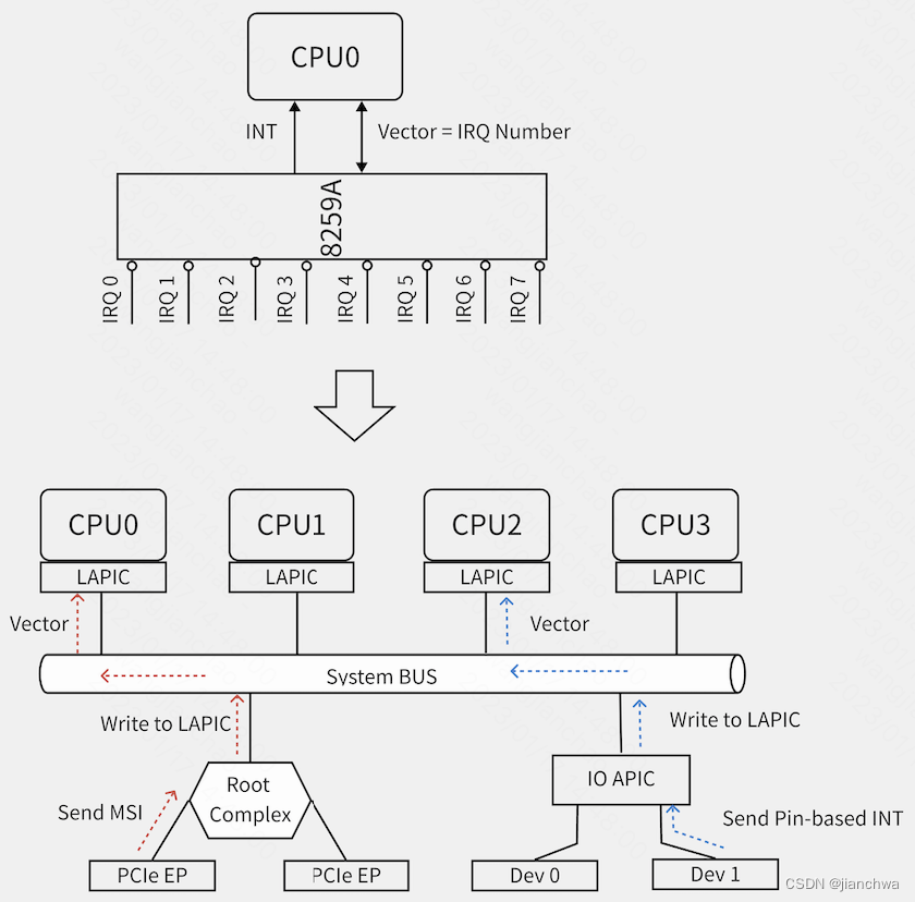
1.2 APIC
APIC,包括lapic和ioapic,如下图,解决了多核场景下的中断分发问题;
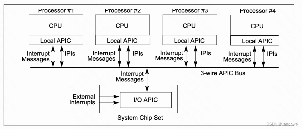
在MSI/MIS-X,引入之后,IOAPIC变得没有必要,设备通过对lapic的pci写事务触发中断
lapic主要处理以下中断源:
- 本地,包括APIC timer generated interrupts,用作sched_tick时钟中断
- IPI ,用作reschedule ipi和smp call function
- 外部中断源,可能来自IOAPIC或者MSI/MSI-X
lapic的配置通过MMIO进行,基址为0xFEE00000H;每个CPU的lapic的寄存器的地址都是一样的;
注:Bits 31-20 of Message Address Register of MSI;These bits contain a fixed value for interrupt messages (0FEEH). This value locates interrupts at the 1-MByte area with a base address of 4G – 18M. All accesses to this region are directed as interrupt messages
X2APIC配置使用MSR,其速度比MMIO更快。
本地中断源需要配置Local Vector Table,详情可以参考Intel SDM 3 10.5.1 Local Vector Table

__setup_APIC_LVTT()
---
	lvtt_value = LOCAL_TIMER_VECTOR;
	if (!oneshot)
		lvtt_value |= APIC_LVT_TIMER_PERIODIC;
	else if (boot_cpu_has(X86_FEATURE_TSC_DEADLINE_TIMER))
		lvtt_value |= APIC_LVT_TIMER_TSCDEADLINE;

	if (!lapic_is_integrated())
		lvtt_value |= SET_APIC_TIMER_BASE(APIC_TIMER_BASE_DIV);

	if (!irqen)
		lvtt_value |= APIC_LVT_MASKED;

	apic_write(APIC_LVTT, lvtt_value);
---
IPI,interprocessor interrupt,APIC的ICR,interrupt control register,用于控制其发送。寄存器格式:
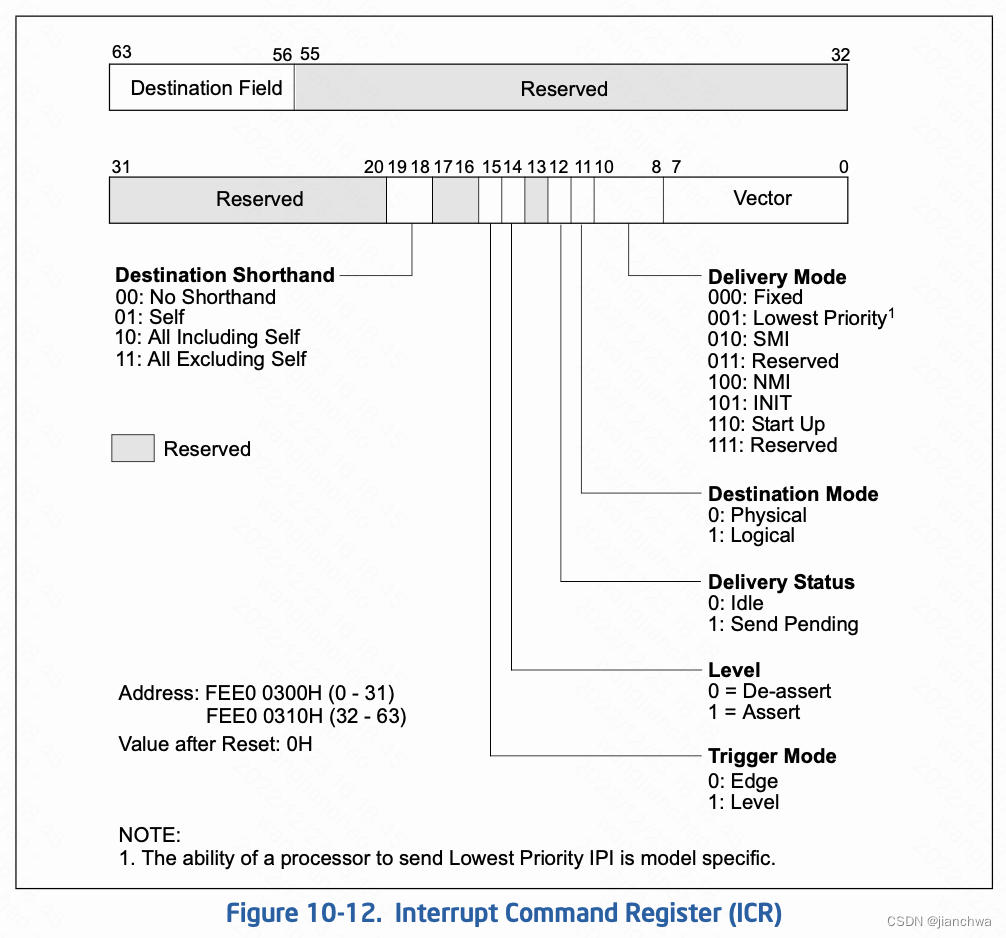
IPI的两个主要的使用场景是,resched和smp call function,参考代码:
resched_curr()
  -> smp_send_reschedule()
    -> native_smp_send_reschedule()
      -> apic->send_IPI(cpu, RESCHEDULE_VECTOR);


smp_call_function_many()
  -> arch_send_call_function_ipi_mask()
	 -> native_send_call_func_ipi()
	    ---
		if (cpumask_equal(mask, allbutself) &&
		    cpumask_equal(cpu_online_mask, cpu_callout_mask))
			apic->send_IPI_allbutself(CALL_FUNCTION_VECTOR);
		else
			apic->send_IPI_mask(mask, CALL_FUNCTION_VECTOR);
		---
__x2apic_send_IPI_mask()
---
	local_irq_save(flags);

	this_cpu = smp_processor_id();
	for_each_cpu(query_cpu, mask) {
		if (apic_dest == APIC_DEST_ALLBUT && this_cpu == query_cpu)
			continue;
		__x2apic_send_IPI_dest(per_cpu(x86_cpu_to_apicid, query_cpu),
				       vector, APIC_DEST_PHYSICAL);
		  -> native_x2apic_icr_write()
	        -> wrmsrl(APIC_BASE_MSR + (APIC_ICR >> 4), ((__u64) id) << 32 | low);
	}
	local_irq_restore(flags)
---
(IOAPC的东西因为懒,所以就不呈现了)
1.3 MSI
在MSI/MIS-X,引入之后,IOAPIC变得没有必要,设备通过对lapic的pci写事务触发中断;
Reducing Interrupt Latency Through the Use of Message Signaled Interrupts![]() https://www.intel.com/content/dam/www/public/us/en/documents/white-papers/msg-signaled-interrupts-paper.pdfExternal Interrupts in the x86 system. Part 1. Interrupt controller evolution / HabrThis article is about the interrupt delivery process from external devices in the x86 system. It tries to answer questions such as: What is PIC and what is it for? What is APIC and what is it for?...
https://www.intel.com/content/dam/www/public/us/en/documents/white-papers/msg-signaled-interrupts-paper.pdfExternal Interrupts in the x86 system. Part 1. Interrupt controller evolution / HabrThis article is about the interrupt delivery process from external devices in the x86 system. It tries to answer questions such as: What is PIC and what is it for? What is APIC and what is it for?... https://habr.com/en/post/446312/上面的连接比较系统的说明的PIC/APIC/MSI的演化和对比;
Interrupts Delivery in a Multi-host Environment![]() https://www3.cs.stonybrook.edu/~live3/files/pcie-interrupt-delivery.pdf上面的连接则介绍的MSI的原理,以下内容主要参考该连接。
https://www3.cs.stonybrook.edu/~live3/files/pcie-interrupt-delivery.pdf上面的连接则介绍的MSI的原理,以下内容主要参考该连接。
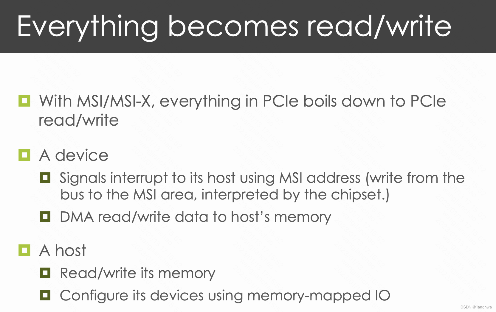
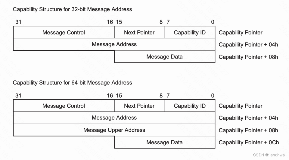
消息的格式为:

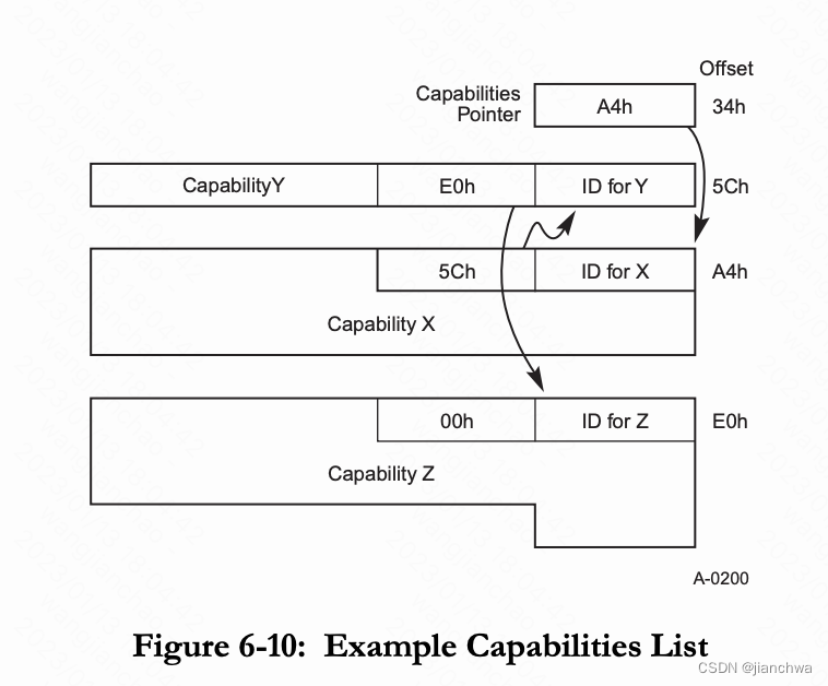
MSI Address和MSI Data的设置,参考连接
PCI Local Bus Specification Revision 3.0![]() https://www.cl.cam.ac.uk/~djm202/pdf/specifications/pci/PCI_LB3.0_CB-2-6-04.pdf6.8.1. Message MSI Capability Structure,它通过Extended PCI Configration Space中的Capability List来设置,
https://www.cl.cam.ac.uk/~djm202/pdf/specifications/pci/PCI_LB3.0_CB-2-6-04.pdf6.8.1. Message MSI Capability Structure,它通过Extended PCI Configration Space中的Capability List来设置,
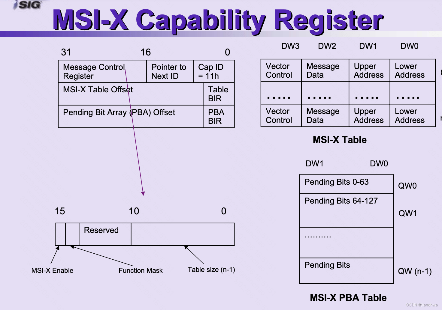
MSI-X has the same features as MSI, the key differences are:
- MSI-X support is optional
- Maximum of 2048 MSI-Xs per function
- MMIO region required for MSI-X tables and Pending Bit Arrays
- Table entries contain unique address and data for each interrupt vector
- Per function vector masking and per vector masking (optional for MSI)
参考连接
Linux-Kernel Archive: Re: Multiple MSI messages support![]() https://lkml.indiana.edu/hypermail/linux/kernel/0710.3/3404.html中,有一段讨论,关于Multiple MSI messages讨论,其中有以下个关键点:
https://lkml.indiana.edu/hypermail/linux/kernel/0710.3/3404.html中,有一段讨论,关于Multiple MSI messages讨论,其中有以下个关键点:
- 由于Intel的APIC的限制,导致x86/64平台无法像PCIE协议中规定的那样,实现MSI多消息;而且,由于x86/64是最先在Linux上支持MSI的,所以,Linux的接口最终也只支持一个Message。
- Linux上Multiple interrupt messages是通过MSI-X支持的;MSI-X table允许每个Message都有一个自己的Data;
- Sparc64 PCI-E controller的MSI支持Multiple message interrupt;
MSI imposes a restriction on how a device generates multiple messages, since there is only one message data register and the rest of the messages must be based on that in a simple way. For example, if the system (or OS) configures the MSI msg data as 0x5000, a device having 4 MSI messages could write 0x5000, 0x5001, 0x5002, 0x5003 to differentiate the MSI messages. And the format of "Intel-style" APIC MSI messages does not match up with the way the PCI spec generates multiple messages. It use the lower 8bits to carry the vector number.
2 irq子系统
2.1 irq domain
为什么需要irq domain ? irq控制器经历了如下图的变化,
iommu甚至还引入了irq remapping,参考连接:Interrupts Delivery in a Multi-host Environment![]() https://www3.cs.stonybrook.edu/~live3/files/pcie-interrupt-delivery.pdf
https://www3.cs.stonybrook.edu/~live3/files/pcie-interrupt-delivery.pdf
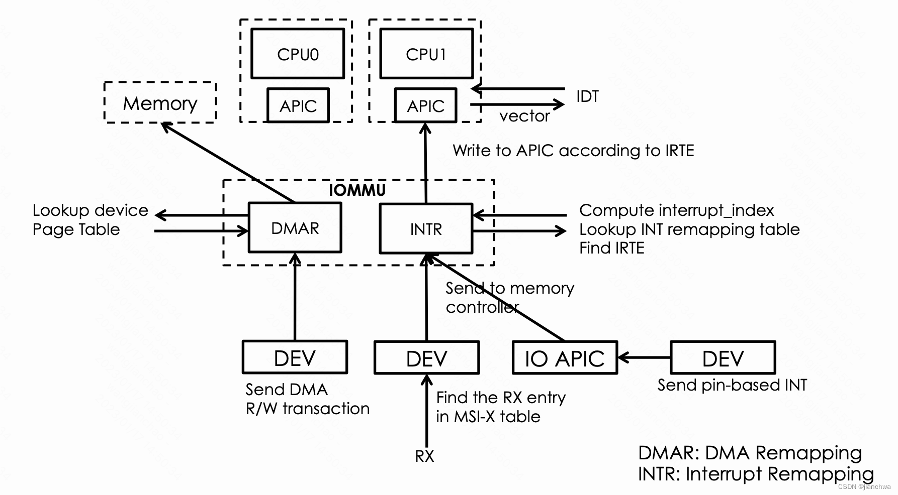
最开始,irq跟vector是相等的,中断的申请和设置,只需要甚至得到irq number,然后把它设置给PIC上设备对应的INT引脚即可;然后,随着irq controller边的越来越复杂,irq在不同的层级上有不同的含义以及数值,参考上图中:
- 在PCI设备上,irq是msi_address和msi_data;
- 在IOMMU上,irq是从addr.handle + data.subhandle计算出的index及其对应的IRTE
- 在CPU上,irq是interrupt vector
所以,引入了irq domain,在上图中,有三个irq domain,msi、ir和vector。
2.2 irq数据结构概述
本小节给出了irq核心数据结构的关系,及其典型赋值。
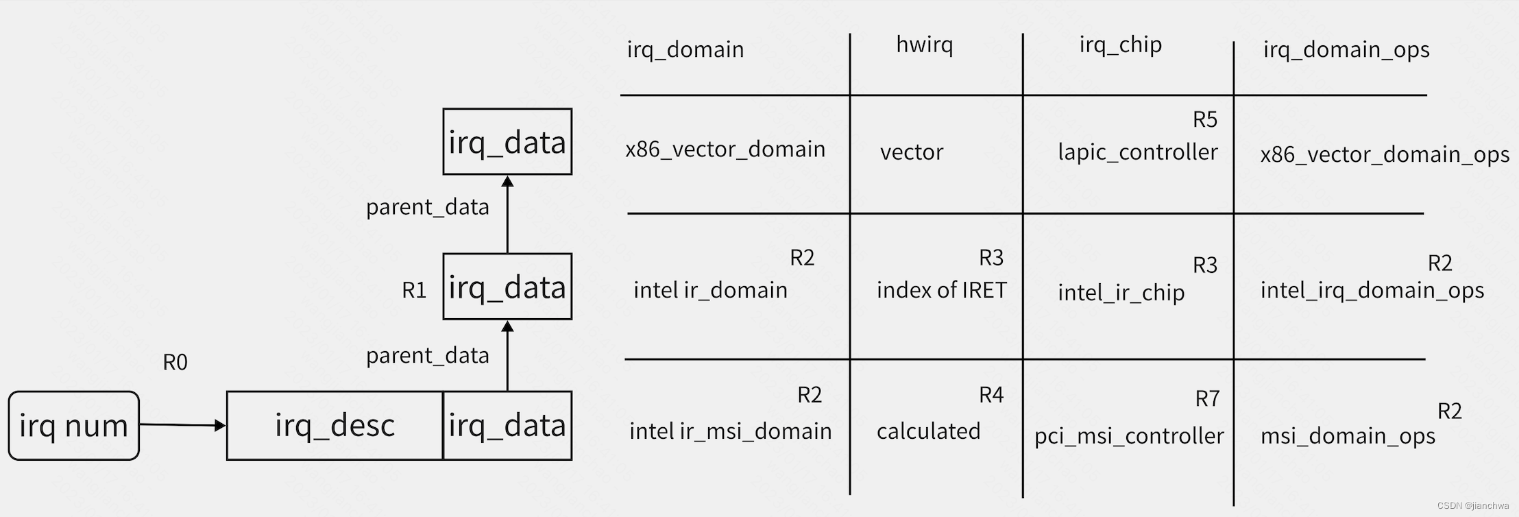
注:irq_chip对应的是该层级的操作方法集合;
- R0,全局唯一的irq num,对应这一个irq_desc结构,参考代码:
使用Bitmap维护空闲的irq number __irq_alloc_descs() --- start = bitmap_find_next_zero_area(allocated_irqs, IRQ_BITMAP_BITS, from, cnt, 0); ... ret = alloc_descs(start, cnt, node, affinity, owner); --- irq number与irq_desc的对应关系,使用radix tree维护 struct irq_desc *irq_to_desc(unsigned int irq) { return radix_tree_lookup(&irq_desc_tree, irq); } - R1,irq_data是irq_desc的内嵌结构,使用它来维护per-irq的irq_domain的层级结构;层级结构的建立参考代码
__irq_domain_alloc_irqs() -> irq_domain_alloc_irq_data() --- //此处获得的irq_data是irq_desc的内嵌结构 irq_data = irq_get_irq_data(virq + i); irq_data->domain = domain; // 此处会建立irq_data的层级结构 for (parent = domain->parent; parent; parent = parent->parent) { irq_data = irq_domain_insert_irq_data(parent, irq_data); ... } --- -> irq_domain_alloc_irq_data() --- irq_data = kzalloc_node(sizeof(*irq_data), GFP_KERNEL, irq_data_get_node(child)); if (irq_data) { child->parent_data = irq_data; irq_data->irq = child->irq; irq_data->common = child->common; irq_data->domain = domain; } --- - R2,此处涉及的是irq_domain的层级结构的建立,参考代码:
intel_setup_irq_remapping() --- iommu->ir_domain = irq_domain_create_hierarchy(arch_get_ir_parent_domain(), 0, INTR_REMAP_TABLE_ENTRIES, fn, &intel_ir_domain_ops, iommu); iommu->ir_msi_domain = arch_create_remap_msi_irq_domain(iommu->ir_domain, "INTEL-IR-MSI", iommu->seq_id); --- static inline struct irq_domain *arch_get_ir_parent_domain(void) { return x86_vector_domain; } arch_create_remap_msi_irq_domain() -> pci_msi_create_irq_domain() // pci_msi_ir_domain_info -> msi_create_irq_domain() -> irq_domain_create_hierarchy() // msi_domain_ops - R3,ir_domain的hwirq参考代码
intel_irq_remapping_alloc() --- down_read(&dmar_global_lock); index = alloc_irte(iommu, virq, &data->irq_2_iommu, nr_irqs); up_read(&dmar_global_lock); ... for (i = 0; i < nr_irqs; i++) { irq_data = irq_domain_get_irq_data(domain, virq + i); ... irq_data->hwirq = (index << 16) + i; irq_data->chip_data = ird; irq_data->chip = &intel_ir_chip; intel_irq_remapping_prepare_irte(ird, irq_cfg, info, index, i); irq_set_status_flags(virq + i, IRQ_MOVE_PCNTXT); } --- - R4,参考代码:
irq_hw_number_t pci_msi_domain_calc_hwirq(struct pci_dev *dev, struct msi_desc *desc) { return (irq_hw_number_t)desc->msi_attrib.entry_nr | PCI_DEVID(dev->bus->number, dev->devfn) << 11 | (pci_domain_nr(dev->bus) & 0xFFFFFFFF) << 27; } - R5,参考代码:
x86_vector_alloc_irqs()
---
	for (i = 0; i < nr_irqs; i++) {
		irqd = irq_domain_get_irq_data(domain, virq + i);
		...
		irqd->chip = &lapic_controller;
		irqd->chip_data = apicd;
		irqd->hwirq = virq + i;

		err = assign_irq_vector_policy(irqd, info);
	}
---
2.3 irq申请
irq的申请涉及层级结构的遍历,依次为:
- ir_msi_domain
- ir_domain
- x86_vector_domain
中断申请的起点是:
pci_msi_setup_msi_irqs()
  -> arch_setup_msi_irqs()
	-> x86_msi.setup_msi_irqs()
	   native_setup_msi_irqs()
	   ---
		domain = irq_remapping_get_irq_domain(&info);

		return msi_domain_alloc_irqs(domain, &dev->dev, nvec);
	   ---

irq_remapping_get_irq_domain()
  -> remap_ops->get_irq_domain()
	 intel_get_irq_domain()
	 ---
	switch (info->type) {
	case X86_IRQ_ALLOC_TYPE_MSI:
	case X86_IRQ_ALLOC_TYPE_MSIX:
		iommu = map_dev_to_ir(info->msi_dev);
		if (iommu)
			return iommu->ir_msi_domain;
		break;
	default:
		break;
	}

	return NULL;
	 ---
没有使用msi_default_domain是因为它的parent被设置为x86_vector_domain。
msi_domain_alloc_irqs()主要有两个步骤:
- alloc,对应函数__irq_domain_alloc_irqs()
- activate,对应函数irq_domain_activate_irq
首先进入alloc函数:
msi_domain_alloc_irqs()
  -> __irq_domain_alloc_irqs()
	 -> irq_domain_alloc_descs()
	   -> __irq_alloc_descs()
	-> irq_domain_alloc_irq_data()
	-> irq_domain_alloc_irqs_hierarchy()
我们看到,这里主要做了三件事:
- __irq_domain_alloc_descs,这里会申请空闲的irq number,及其对应的irq_desc,参考R0;
- irq_domain_alloc_irq_data,这里会建立irq_data层级关系;
- irq_domain_alloc_irqs_hierarchy进入irq_domain的alloc函数;
参考msi_domain_ops和intel_ir_domain_ops的alloc函数,
msi_domain_alloc()
---
	if (domain->parent) {
		ret = irq_domain_alloc_irqs_parent(domain, virq, nr_irqs, arg);
		if (ret < 0)
			return ret;
	}

	for (i = 0; i < nr_irqs; i++) {
		ret = ops->msi_init(domain, info, virq + i, hwirq + i, arg);
		...
	}
---

intel_irq_remapping_alloc()
---
	ret = irq_domain_alloc_irqs_parent(domain, virq, nr_irqs, arg);
	...
	data = kzalloc(sizeof(*data), GFP_KERNEL);
	...
	down_read(&dmar_global_lock);
	index = alloc_irte(iommu, virq, &data->irq_2_iommu, nr_irqs);
	up_read(&dmar_global_lock);
	...
---
均首先调用了parent domain的alloc函数,这就是irq_domain层级发挥作用的方式。
activate的过程也与这个类似;参考函数:
__irq_domain_activate_irq()
---
	if (irqd && irqd->domain) {
		struct irq_domain *domain = irqd->domain;

		if (irqd->parent_data)
			ret = __irq_domain_activate_irq(irqd->parent_data,
							reserve);
		if (!ret && domain->ops->activate) {
			ret = domain->ops->activate(domain, irqd, reserve);
			...
		}
	}
---
下面看下各个domain分别是如何进行alloc和activate的;
2.3.1 x86_vector_domain
x86架构下,每个CPU有256个vector,其中前32个是reserve给系统的trap、fault和abort的,参考连接:Exceptions - OSDev Wikihttps://wiki.osdev.org/Exceptions
还有一个部分,也被reserve了,比如:
#define ERROR_APIC_VECTOR		0xfe
#define RESCHEDULE_VECTOR		0xfd
#define CALL_FUNCTION_VECTOR		0xfc
#define CALL_FUNCTION_SINGLE_VECTOR	0xfb
#define THERMAL_APIC_VECTOR		0xfa
#define THRESHOLD_APIC_VECTOR		0xf9
#define REBOOT_VECTOR			0xf8
留给我们可以自由申请的,通过irq_matrix维护了起来;
x86_vector_domain的alloc函数就是从这个irq_matrix (per-cpu bitmap)中申请空闲vector;
以nvme irq为例,其申请的是managed irq,allocate和activate过程参考代码:
注: The affinity of managed interrupts is completely handled in the kernel and cannot be changed via the /proc/irq/* interfaces from user space. 这是managed irq区别于普通irq的区别
- allocate,在目标cpu上reserve一个vector
x86_vector_alloc_irqs()
  -> assign_irq_vector_policy()
    -> reserve_managed_vector()
      -> irq_matrix_reserve_managed()
- activate,将目标cpu上reseve的vector 安装上
x86_vector_activate()
  -> activate_managed()
	-> assign_managed_vector()
	   ---
		vector = irq_matrix_alloc_managed(vector_matrix, vector_searchmask,
					  &cpu);
		...
		apic_update_vector(irqd, vector, cpu);
	   ---
apic_update_vector()
---
	apicd->vector = newvec;
	apicd->cpu = newcpu;
	per_cpu(vector_irq, newcpu)[newvec] = desc;
---


选择好CPU之后,会将对应的irq desc安装到该CPU的对应slot上,
在发生IRQ时,会依据vector获取irq desc,并获取对应的action
do_IRQ()
---
	unsigned vector = ~regs->orig_ax;

	entering_irq();
	desc = __this_cpu_read(vector_irq[vector]);
	handle_irq(desc, regs);
	exiting_irq();
---
注:对于managed irq,在allocate环节reserve vector时,如果irq affinity中包含多个cpu,那么它会在这些cpu上都reserve一个vector,然后在activate时,选择vector使用最少的那个cpu;这些reserve的vector可能在cpuhotplug时使用,参考migrate_one_irq()
2.3.2 intel ir_domain
irq remapping的详细分析,我们会另开一个小节;这里只关注alloc和activate;
- alloc,申请一个IRET的index,
intel_irq_remapping_alloc() --- down_read(&dmar_global_lock); index = alloc_irte(iommu, virq, &data->irq_2_iommu, nr_irqs); up_read(&dmar_global_lock); ... for (i = 0; i < nr_irqs; i++) { irq_data = irq_domain_get_irq_data(domain, virq + i); ... irq_data->hwirq = (index << 16) + i; irq_data->chip_data = ird; irq_data->chip = &intel_ir_chip; intel_irq_remapping_prepare_irte(ird, irq_cfg, info, index, i); irq_set_status_flags(virq + i, IRQ_MOVE_PCNTXT); } --- - activate,主要是将x86_vector_domain中申请的vector和对应的cpu设置到IRET中,参考代码:
intel_irq_remapping_activate()
  -> intel_ir_reconfigure_irte()
	 ---
	struct intel_ir_data *ir_data = irqd->chip_data;
	struct irte *irte = &ir_data->irte_entry;
	struct irq_cfg *cfg = irqd_cfg(irqd);

	/*
	 * Atomically updates the IRTE with the new destination, vector
	 * and flushes the interrupt entry cache.
	 */
	irte->vector = cfg->vector;
	irte->dest_id = IRTE_DEST(cfg->dest_apicid);

	/* Update the hardware only if the interrupt is in remapped mode. */
	if (force || ir_data->irq_2_iommu.mode == IRQ_REMAPPING)
		modify_irte(&ir_data->irq_2_iommu, irte);
	 ---

irqd_cfg come from apic_update_irq_cfg()
2.3.3 intel ir_msi_domain
在msi操作流程中,有一个关键结构体,msi_domain_info,对于本domain,它的值是:
arch_create_remap_msi_irq_domain()
  -> pci_msi_create_irq_domain() // msi_domain_info = pci_msi_ir_domain_info
    -> pci_msi_domain_update_dom_ops() // MSI_FLAG_USE_DEF_DOM_OPS
	  -> merge pci_msi_domain_ops with pci_msi_domain_ops_default
	-> irq_domain_create_hierarchy() // irq_domain_ops = msi_domain_ops

static struct irq_chip pci_msi_ir_controller = {
	.name			= "IR-PCI-MSI",
	.irq_unmask		= pci_msi_unmask_irq,
	.irq_mask		= pci_msi_mask_irq,
	.irq_ack		= irq_chip_ack_parent,
	.irq_retrigger		= irq_chip_retrigger_hierarchy,
	.irq_set_vcpu_affinity	= irq_chip_set_vcpu_affinity_parent,
	.flags			= IRQCHIP_SKIP_SET_WAKE,
};

static struct msi_domain_info pci_msi_ir_domain_info = {
	.flags		= MSI_FLAG_USE_DEF_DOM_OPS | MSI_FLAG_USE_DEF_CHIP_OPS |
			  MSI_FLAG_MULTI_PCI_MSI | MSI_FLAG_PCI_MSIX,
	.ops		= &pci_msi_domain_ops,
	.chip		= &pci_msi_ir_controller,
	.handler	= handle_edge_irq,
	.handler_name	= "edge",
};

pci_msi_domain_ops的操作会和pci_msi_domain_ops_defaultmerge起来
这些回调函数会在msi domain的操作中用到;
- alloc,
msi_domain_alloc()
---
	if (domain->parent)
		ret = irq_domain_alloc_irqs_parent(domain, virq, nr_irqs, arg);
	...
	for (i = 0; i < nr_irqs; i++)
		ret = ops->msi_init(domain, info, virq + i, hwirq + i, arg);
	...
---

msi_domain_ops_init()
---
	irq_domain_set_hwirq_and_chip(domain, virq, hwirq, info->chip,
				      info->chip_data);
	if (info->handler && info->handler_name) {
		__irq_set_handler(virq, info->handler, 0, info->handler_name);
		if (info->handler_data)
			irq_set_handler_data(virq, info->handler_data);
	}
---
并没有特别的资源的申请,主要是一些初始化操作,其中大量用到了msi_domain_info;
-
activate,主要是设置msi address和data,参考代码:
msi_domain_activate()
  -> irq_chip_compose_msi_msg()
	-> intel_ir_compose_msi_msg()
	  ---
		*msg = ir_data->msi_entry;
	  ---


intel_irq_remapping_alloc()
---
	for (i = 0; i < nr_irqs; i++) {
		irq_data = irq_domain_get_irq_data(domain, virq + i);
		...
		irq_data->hwirq = (index << 16) + i;
		irq_data->chip_data = ird;
		irq_data->chip = &intel_ir_chip;
		intel_irq_remapping_prepare_irte(ird, irq_cfg, info, index, i);
	}
---
intel_irq_remapping_prepare_irte()
---
	struct msi_msg *msg = &data->msi_entry;
	...
	switch (info->type) {
	case X86_IRQ_ALLOC_TYPE_IOAPIC:
		...
		break;

	case X86_IRQ_ALLOC_TYPE_HPET:
	case X86_IRQ_ALLOC_TYPE_MSI:
	case X86_IRQ_ALLOC_TYPE_MSIX:
		...
		msg->address_hi = MSI_ADDR_BASE_HI;
		msg->data = sub_handle;
		msg->address_lo = MSI_ADDR_BASE_LO | MSI_ADDR_IR_EXT_INT |
				  MSI_ADDR_IR_SHV |
				  MSI_ADDR_IR_INDEX1(index) |
				  MSI_ADDR_IR_INDEX2(index);
		break;
	default:
		BUG_ON(1);
		break;
	}
---

如果没有irq remapping,则是下面的代码:

irq_msi_compose_msg()
---
	msg->address_hi = MSI_ADDR_BASE_HI;

	if (x2apic_enabled())
		msg->address_hi |= MSI_ADDR_EXT_DEST_ID(cfg->dest_apicid);

	msg->address_lo =
		MSI_ADDR_BASE_LO |
		((apic->irq_dest_mode == 0) ?
			MSI_ADDR_DEST_MODE_PHYSICAL :
			MSI_ADDR_DEST_MODE_LOGICAL) |
		MSI_ADDR_REDIRECTION_CPU |
		MSI_ADDR_DEST_ID(cfg->dest_apicid);

	msg->data =
		MSI_DATA_TRIGGER_EDGE |
		MSI_DATA_LEVEL_ASSERT |
		MSI_DATA_DELIVERY_FIXED |
		MSI_DATA_VECTOR(cfg->vector);

---

其中使用的cfg->dest_apicd和cfg->vector

msi_domain_activate()
  -> irq_chip_compose_msi_msg()
  -> irq_chip_write_msi_msg()
	-> data->chip->irq_write_msi_msg(data, msg);
	   pci_msi_domain_write_msg()
	    -> __pci_write_msi_msg()
	      ---
		if (dev->current_state != PCI_D0 || pci_dev_is_disconnected(dev)) {
			/* Don't touch the hardware now */
		} else if (entry->msi_attrib.is_msix) {
			...
		} else {
			int pos = dev->msi_cap;
			u16 msgctl;

			pci_read_config_word(dev, pos + PCI_MSI_FLAGS, &msgctl);
			msgctl &= ~PCI_MSI_FLAGS_QSIZE;
			msgctl |= entry->msi_attrib.multiple << 4;
			pci_write_config_word(dev, pos + PCI_MSI_FLAGS, msgctl);

			pci_write_config_dword(dev, pos + PCI_MSI_ADDRESS_LO,
					       msg->address_lo);
			if (entry->msi_attrib.is_64) {
				pci_write_config_dword(dev, pos + PCI_MSI_ADDRESS_HI,
						       msg->address_hi);
				pci_write_config_word(dev, pos + PCI_MSI_DATA_64,
					      msg->data);
			} else {
				pci_write_config_word(dev, pos + PCI_MSI_DATA_32,
						      msg->data);
			}
		}
		  ---
MISCs
level or edge
在看中断处理相关代码或者一些相关寄存器的是说明时,经常遇到level还是edge trigger;这里的level还有edge到底什么意思呢?下面的链接中,有些精彩的解释和比喻;
Edge Triggered Vs Level Triggered interrupts![]() http://venkateshabbarapu.blogspot.com/2013/03/edge-triggered-vs-level-triggered.htmllevel还是edge,是设备和CPU之前的一种约定,即响应的IRQ Line上触发什么样的信号时,CPU进入中断状态;
http://venkateshabbarapu.blogspot.com/2013/03/edge-triggered-vs-level-triggered.htmllevel还是edge,是设备和CPU之前的一种约定,即响应的IRQ Line上触发什么样的信号时,CPU进入中断状态;
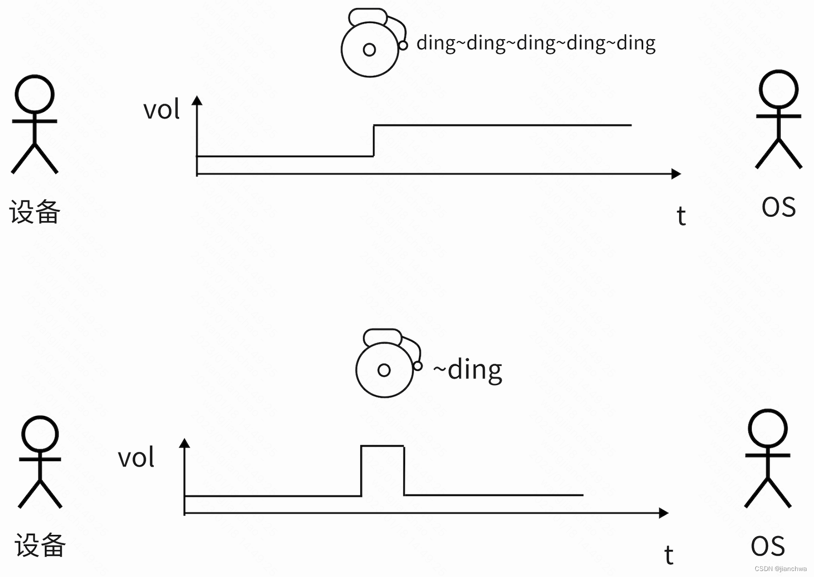
- Level,A level-triggered interrupt module always generates an interrupt whenever the level of the interrupt source is asserted;这里所谓的产生中断,实际上是CPU和设备之间的一种约定,即设备的IRQ Line处于触发态,CPU上就会进入中断状态;
- Edge,An edge-triggered interrupt module generates an interrupt only when it detects an asserting edge of the interrupt source. 此时设备和OS的约定是,当设备的IRQ Line上产生一个上升或者下降的信号变化,CPU进入中断状态;
链接中谈到了level和edge的各自优缺点:
- edge trigger容易导致中断丢失,这其实是考虑比较简单的系统,比如基于arm的小型嵌入式设备;但是对于intel平台,其apic会记录IRQ line的状态,可以避免中断丢失的情况;
- level trigger需要ISR去ack IRQ source,让后者reset IRQ line,据说这会增加设备的设计难度,参考连接Level-triggered vs. Edge-triggered Interrupts
 https://www.garystringham.com/level-triggered-vs-edge-triggered-interrupts/#:~:text=Level-Triggered%3A%20A%20level-,edge%20of%20the%20interrupt%20source.
Linux内核中,针对level和edge的处理函数也有所不同,参考函数handle_level_irq()和handle_edge_irq();两个函数的处理逻辑,基于这样的设定:
- 对于level trigger,需要在ack irq之前,把它mask掉,这样可以避免在ack之后,再次触发;
- 对于edge trigger,并不需要做mask,但是,这也会导致相同的中断可能在一个cpu处理的同时,再次被发送到另外一个cpu上,为了避免ISR被多个cpu同时调用,edge trigger irq做了特殊的处理;


 8756
8756


 被折叠的 条评论
为什么被折叠?
被折叠的 条评论
为什么被折叠?
 到【灌水乐园】发言


