


一、单缸发动机曲轴连杆活塞系统动力学分析参考:
汽车动力总成系统/(伊朗)贝赫鲁兹.马沙迪,(英)戴维.克罗拉著;
白先旭,刘勇强译。——北京:机械工业出版社,2018.6
(汽车先进技术译丛.汽车创新与开发系列)
书名原文:Vehicle Powertrain Systems
ISBN 978-7-111-60005-3
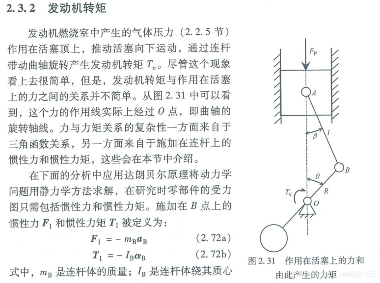
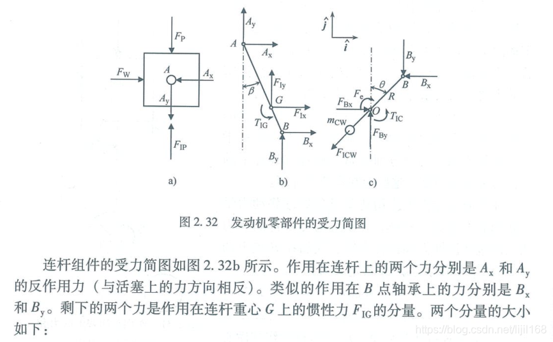
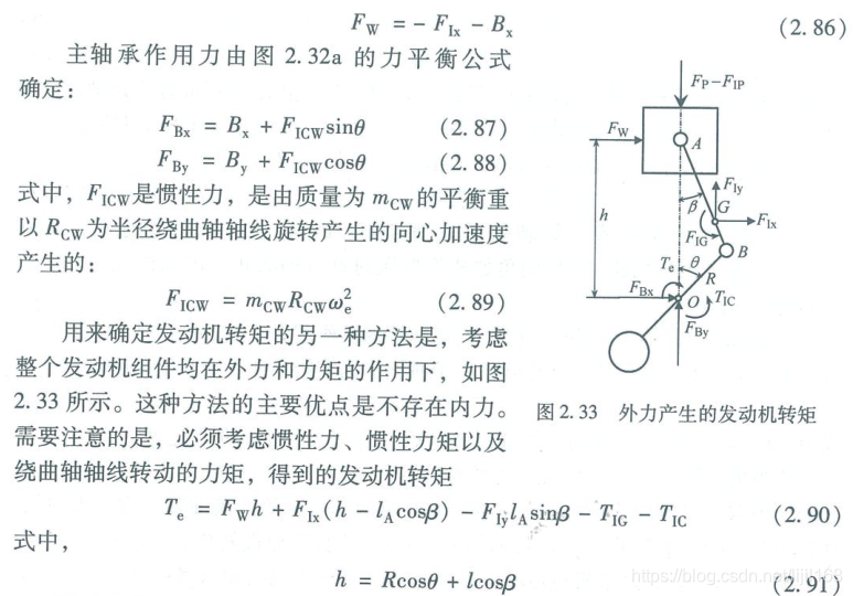
曲柄连杆机构受力分析
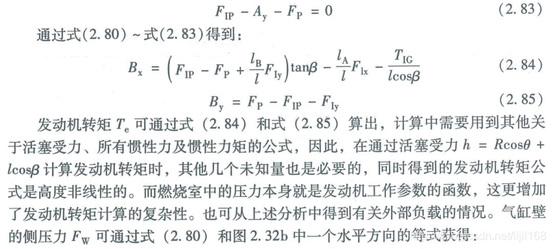
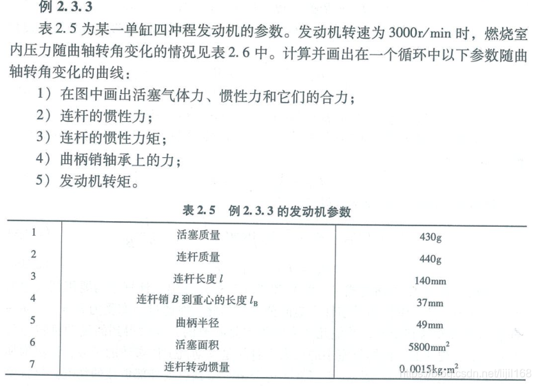
燃烧室压力如下:
X_Column(turn_mn) Y_Column(deg) Z_Column(N_m2)
3000 0 1.82E+06
3000 20 3.24E+06
3000 23 3.29E+06
3000 26 3.24E+06
3000 50 2.03E+06
3000 60 1.52E+06
3000 70 1.01E+06
3000 80 8.10E+05
3000 100 6.08E+05
3000 110 5.07E+05
3000 1
 最低0.47元/天 解锁文章


 1255
1255

 被折叠的 条评论
为什么被折叠?
被折叠的 条评论
为什么被折叠?
 到【灌水乐园】发言


