


vtkProbeFilter类
vtkProbeFilter类可以在指定点位置采样数据值,可以在指定点位置过滤源数据的标量数据(标量值、向量值),是一种过滤器类;vtkProbeFilter类支持两种输入,包括了输入过滤几何结构和待过滤的源数据;在计算指定点位置数值时,将采用插值算法计算;vtkProbeFilter类复制每个指定点位置的源数据到输出中。
vtkProbeFilter类可以在三维体数据中过滤一个平面所经过的源数据,类似MPR功能;
vtkProbeFilter类也可以重新采样数据,或将一个数据集DataSet转换为另一个数据集DataSet。例如:可以使用体积(三维vtkImageData)探测非结构化网格(vtkUnstructuredGrid),然后使用体积渲染技术将结果可视化。或者用一条直线或曲线探测数据,从而沿着该直线或曲线生成x-y图。如果是曲线重建曲面投影,就是CPR的功能了;
vtkProbeFilter类可以实现切面重建、曲面重建,需要注意的是vtkProbeFilter类的输出结果并不是vtkImageData而是vtkDataSet;如果给vtkProbeFilter类一个平面,他会产生和vtkImageReslice类一样的渲染效果,如果给他一个不规则的点集+拓扑结构,他会生成一个不规则的曲面重建;
示例
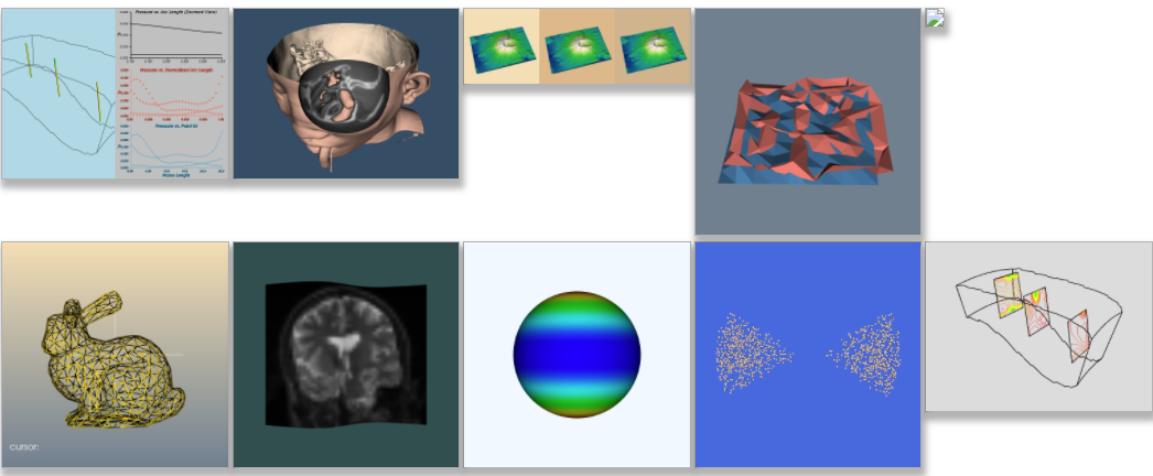
官网CurvedReformation例子
namespace {
    vtkSmartPointer<vtkPolyData> SweepLine(vtkPolyData* line, double direction[3],
    	double distance, unsigned int cols);
}

int main(int, char*[])
{
    vtkNew<vtkNamedColors> colors;
    // Parse arguments
    std::string volumeFileName = "G:\\Data\\HeadMRVolume.mhd";
    std::string polyDataFileName = "G:\\Data\\polyline.vtk";;
    unsigned int resolution = 100;

    // Read the volume data
    vtkNew<vtkImageReader2Factory> imageFactory;
    vtkSmartPointer<vtkImageReader2> imageReader;
    imageReader.TakeReference(imageFactory->CreateImageReader2(volumeFileName.c_str()));
    imageReader->SetFileName(volumeFileName.c_str());
    imageReader->Update();

    // Read the Polyline
    vtkNew<vtkPolyDataReader> polyLineReader;
    polyLineReader->SetFileName(polyDataFileName.c_str());
    polyLineReader->Update();

    vtkNew<vtkSplineFilter> spline;
    spline->SetInputConnection(polyLineReader->GetOutputPort());
    spline->SetSubdivideToSpecified();
    spline->SetNumberOfSubdivisions(resolution);

    // Sweep the line to form a surface
    double direction[3];
    direction[0] = 0.0;
    direction[1] = 0.0;
    direction[2] = 1.0;
    double distance = 164;
    spline->Update();
    auto surface = SweepLine(spline->GetOutput(), direction, distance, 100);

    // Probe the volume with the extruded surface
    vtkNew<vtkProbeFilter> sampleVolume;
    sampleVolume->SetInputData(1, imageReader->GetOutput());
    sampleVolume->SetInputData(0, surface);

    // Compute a simple window/level based on scalar range
    vtkNew<vtkWindowLevelLookupTable> wlLut;
    double range = imageReader->GetOutput()->GetScalarRange()[1] -
        imageReader->GetOutput()->GetScalarRange()[0];
    double level = (imageReader->GetOutput()->GetScalarRange()[1] +
        imageReader->GetOutput()->GetScalarRange()[0]) / 2.0;
    wlLut->SetWindow(range);
    wlLut->SetLevel(level);

    // Create a mapper and actor.
    vtkNew<vtkDataSetMapper> mapper;
    mapper->SetInputConnection(sampleVolume->GetOutputPort());
    mapper->SetLookupTable(wlLut);
    mapper->SetScalarRange(0, 255);

    vtkNew<vtkActor> actor;
    actor->SetMapper(mapper);

    // Create a renderer, render window, and interactor
    vtkNew<vtkRenderer> renderer;
    vtkNew<vtkRenderWindow> renderWindow;
    renderWindow->AddRenderer(renderer);
    renderWindow->SetWindowName("CurvedReformation");

    vtkNew<vtkRenderWindowInteractor> renderWindowInteractor;
    renderWindowInteractor->SetRenderWindow(renderWindow);

    // Add the actors to the scene
    renderer->AddActor(actor);
    renderer->SetBackground(colors->GetColor3d("DarkSlateGray").GetData());

    // Set the camera for viewing medical images
    renderer->GetActiveCamera()->SetViewUp(0, 0, 1);
    renderer->GetActiveCamera()->SetPosition(0, 0, 0);
    renderer->GetActiveCamera()->SetFocalPoint(0, 1, 0);
    renderer->ResetCamera();

    // Render and interact
    renderWindow->Render();
    renderWindowInteractor->Start();
    return 0;
}

namespace {
    vtkSmartPointer<vtkPolyData> SweepLine(vtkPolyData* line, double direction[3],
        double distance, unsigned int cols)
    {
        unsigned int rows = line->GetNumberOfPoints();
        double spacing = distance / cols;
        vtkNew<vtkPolyData> surface;

        // Generate the points
        cols++;
        unsigned int numberOfPoints = rows * cols;
        unsigned int numberOfPolys = (rows - 1) * (cols - 1);
        vtkNew<vtkPoints> points;
        points->Allocate(numberOfPoints);
        vtkNew<vtkCellArray> polys;
        polys->Allocate(numberOfPolys * 4);

        double x[3];
        unsigned int cnt = 0;
        for (unsigned int row = 0; row < rows; row++) {
            for (unsigned int col = 0; col < cols; col++) {
                double p[3];
                line->GetPoint(row, p);
                x[0] = p[0] + direction[0] * col * spacing;
                x[1] = p[1] + direction[1] * col * spacing;
                x[2] = p[2] + direction[2] * col * spacing;
                points->InsertPoint(cnt++, x);
            }
        }
        // Generate the quads
        vtkIdType pts[4];
        for (unsigned int row = 0; row < rows - 1; row++) {
            for (unsigned int col = 0; col < cols - 1; col++) {
                pts[0] = col + row * (cols);
                pts[1] = pts[0] + 1;
                pts[2] = pts[0] + cols + 1;
                pts[3] = pts[0] + cols;
                polys->InsertNextCell(4, pts);
            }
        }
        surface->SetPoints(points);
        surface->SetPolys(polys);

        return surface;
    }
} // namespace


如果将SweepLine返回的vtkPolygonData展示成线的话,就是下面的效果:
vtkNew<vtkExtractEdges> extract;
extract->SetInputData(surface);
extract->Update();

vtkNew<vtkPolyDataMapper> mapper;
mapper->SetInputData(extract->GetOutput());

将输入的polyline.vtk显示出来后,可以发现白色的网格是有红色的曲线向一个方向生成的;

代码阅读
main函数
1.使用vtkImageReader2类和vtkPolyDataReader类分别解读文件HeadMRVolume.mhd/HeadMRVolume.raw和文件polyline.vtk;HeadMRVolume.mhd/HeadMRVolume.raw内是一组CT序列,文件polyline.vtk是折线的几何结构内容;
2.使用vtkSplineFilter对折线进行插值,生成一条曲线;
3.使用方法SweepLine,由之前的曲线,生成一个vtkPolyData的曲面对象,如上图中显示的网格;
4.设置vtkProbeFilter的两个输入:输入0为vtkPolyData的曲面对象surface;输入1为数据源imageReader->GetOutput();
5.根据数据源imageReader->GetOutput()数据的范围来设置映射表vtkWindowLevelLookupTable类的SetWindow和SetLevel;
6.vtkDataSetMapper设置了SetLookupTable和SetScalarRange(0, 255);
7.进入渲染管线;
-----------------------------------------------------------------------------------------------------------------------------------------------------------------
SweepLine方法
1.计算待生成的surface的行数为曲线上点的个数line->GetNumberOfPoints(),根据distance和cols得到列方向上的spacing;
2.计算surface内点的个数numberOfPoints为rows * cols,单元个数为(rows - 1) * (cols - 1);
3.生成vtkPoints类对象points和vtkCellArray类对象polys;
4.遍历生成每行每列的点坐标,放入points中;每临近的四个点构成一个单元InsertNextCell(4, pts);
5.设定surface对象的SetPoints(points)和SetPolys(polys);
6.返回surface对象;
SweepLine是从曲线向一个方向的扫描,如果是从曲线向两端扫描,结果就类似CPR的功能了,只是需要将结果放在一个平面的二维图像上;
将vtkProbeFilter的结果转换为vtkImageData结果集,由于SweepLine方法中是以曲线作为了行Row,向direction方向延伸出了Col列;根据资料1,将数据集做转换;
    vtkSmartPointer<vtkPolyData> final_poly = sampleVolume->GetPolyDataOutput();
    vtkSmartPointer<vtkImageData> final_image = vtkSmartPointer<vtkImageData>::New();
    final_image->SetDimensions(resolution + 1, resolution + 1, 1);
    final_image->AllocateScalars(VTK_DOUBLE, 1);
    final_image->SetSpacing(1, 1, 0);
    int *dims = final_image->GetDimensions();

    for (int y = 0; y < dims[1]; y++) {
        for (int x = 0; x < dims[0]; x++) {
            double *pixel = static_cast<double *>(final_image->GetScalarPointer(x, y, 0));
            double value = final_poly->GetPointData()->GetScalars()->GetTuple1(dims[0] * y + x);
            pixel[0] = value;
        }
    }
结果图像是向右侧倾斜的;

官网TissueLens例子
#include <vtkSphere.h>
#include <vtkClipDataSet.h>
#include <vtkCylinder.h>
int main(int, char*[])
{
    vtkNew<vtkNamedColors> colors;

    std::array<unsigned char, 4> skinColor{ {240, 184, 160, 255} };
    colors->SetColor("SkinColor", skinColor.data());
    std::array<unsigned char, 4> backColor{ {255, 229, 200, 255} };
    colors->SetColor("BackfaceColor", backColor.data());
    std::array<unsigned char, 4> bkg{ {51, 77, 102, 255} };
    colors->SetColor("BkgColor", bkg.data());

    // Read the volume data
    vtkNew<vtkMetaImageReader> reader;
    reader->SetFileName("G:\\Data\\vtk-examples-master\\src\\Testing\\Data\\FullHead.mhd");
    reader->Update();

    // An isosurface, or contour value of 500 is known to correspond to the
    // skin of the patient.
#ifdef USE_FLYING_EDGES
    vtkNew<vtkFlyingEdges3D> skinExtractor;
#else
    vtkNew<vtkMarchingCubes> skinExtractor;
#endif
    skinExtractor->SetInputConnection(reader->GetOutputPort());
    skinExtractor->SetValue(0, 1000);

    // Define a spherical clip function to clip the isosurface
    vtkNew<vtkSphere> clipFunction;
    clipFunction->SetRadius(50);
    clipFunction->SetCenter(73, 52, 15);

    // Clip the isosurface with a sphere
    vtkNew<vtkClipDataSet> skinClip;
    skinClip->SetInputConnection(skinExtractor->GetOutputPort());
    skinClip->SetClipFunction(clipFunction);
    skinClip->SetValue(0);
    skinClip->GenerateClipScalarsOn();
    skinClip->Update();

    vtkNew<vtkDataSetMapper> skinMapper;
    skinMapper->SetInputConnection(skinClip->GetOutputPort());
    skinMapper->ScalarVisibilityOff();

    vtkNew<vtkActor> skin;
    skin->SetMapper(skinMapper);
    skin->GetProperty()->SetDiffuseColor(colors->GetColor3d("SkinColor").GetData());

    vtkNew<vtkProperty> backProp;
    backProp->SetDiffuseColor(colors->GetColor3d("BackfaceColor").GetData());
    skin->SetBackfaceProperty(backProp);

    // Define a model for the "lens". Its geometry matches the implicit
    // sphere used to clip the isosurface
    vtkNew<vtkSphereSource> lensModel;
    lensModel->SetRadius(50);
    lensModel->SetCenter(73, 52, 15);
    lensModel->SetPhiResolution(100);
    lensModel->SetThetaResolution(100);


    // Sample the input volume with the lens model geometry
    vtkNew<vtkProbeFilter> lensProbe;
    lensProbe->SetInputConnection(lensModel->GetOutputPort());
    lensProbe->SetSourceConnection(reader->GetOutputPort());

    // Clip the lens data with the isosurface value
    vtkNew<vtkClipDataSet> lensClip;
    lensClip->SetInputConnection(lensProbe->GetOutputPort());
    lensClip->SetValue(500);
    lensClip->GenerateClipScalarsOff();
    lensClip->Update();

    // Define a suitable grayscale lut
    vtkNew<vtkLookupTable> bwLut;
    bwLut->SetTableRange(-600, 2048);
    bwLut->SetSaturationRange(0, 0);
    bwLut->SetHueRange(0, 0);
    bwLut->SetValueRange(0, 1);
    bwLut->Build();

    vtkNew<vtkDataSetMapper> lensMapper;
    lensMapper->SetInputConnection(lensClip->GetOutputPort());
    lensMapper->SetScalarRange(lensClip->GetOutput()->GetScalarRange());
    lensMapper->SetLookupTable(bwLut);

    vtkNew<vtkActor> lens;
    lens->SetMapper(lensMapper);

    // It is convenient to create an initial view of the data. The FocalPoint
    // and Position form a vector direction. Later on (ResetCamera() method)
    // this vector is used to position the camera to look at the data in
    // this direction.
    vtkNew<vtkCamera> aCamera;
    aCamera->SetViewUp(0, 0, -1);
    aCamera->SetPosition(0, -1, 0);
    aCamera->SetFocalPoint(0, 0, 0);
    aCamera->ComputeViewPlaneNormal();
    aCamera->Azimuth(30.0);
    aCamera->Elevation(30.0);

    // Create the renderer, the render window, and the interactor. The renderer
    // draws into the render window, the interactor enables mouse- and
    // keyboard-based interaction with the data within the render window.
    //
    vtkNew<vtkRenderer> aRenderer;
    vtkNew<vtkRenderWindow> renWin;
    renWin->AddRenderer(aRenderer);

    vtkNew<vtkRenderWindowInteractor> iren;
    iren->SetRenderWindow(renWin);

    // Actors are added to the renderer. An initial camera view is created.
    // The Dolly() method moves the camera towards the FocalPoint,
    // thereby enlarging the image.
    aRenderer->AddActor(lens);
    aRenderer->AddActor(skin);
    aRenderer->SetActiveCamera(aCamera);
    aRenderer->ResetCamera();
    aCamera->Dolly(1.5);

    // Set a background color for the renderer and set the size of the
    // render window (expressed in pixels).
    aRenderer->SetBackground(colors->GetColor3d("BkgColor").GetData());
    renWin->SetSize(640, 480);
    renWin->SetWindowName("TissueLens");

    // Note that when camera movement occurs (as it does in the Dolly()
    // method), the clipping planes often need adjusting. Clipping planes
    // consist of two planes: near and far along the view direction. The
    // near plane clips out objects in front of the plane; the far plane
    // clips out objects behind the plane. This way only what is drawn
    // between the planes is actually rendered.
    aRenderer->ResetCameraClippingRange();

    // Initialize the event loop and then start it.
    renWin->Render();
    iren->Initialize();
    iren->Start();

    return EXIT_SUCCESS;
}
代码阅读
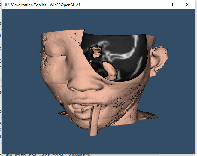
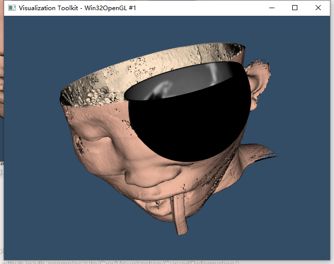
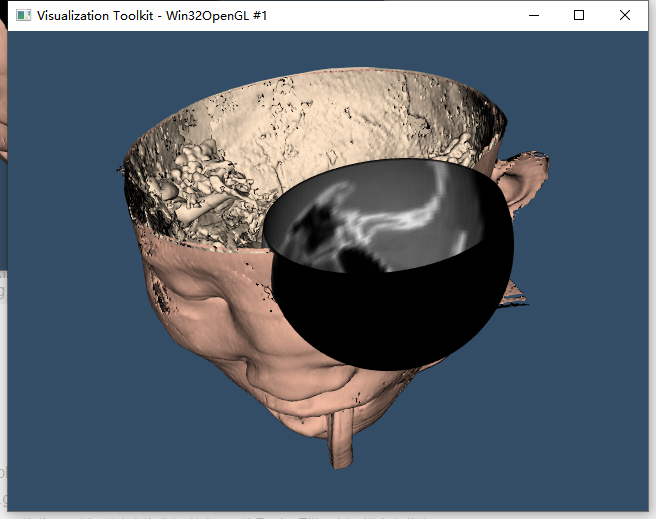
设置lensClip的SetValue设置为0,时,完整的半球灰度可以显示完整,设置为500时,低于500的值就会被抹掉;
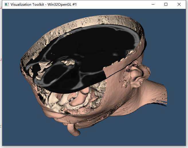
当使用点和单元组成了一个平面时,可以生成一个平面灰度图+多边形的渲染效果;
使用vtkClipDataSet约束了标量CT值的下限;
#include <vtkSphere.h>
#include <vtkClipDataSet.h>
#include <vtkCylinder.h>
int main(int, char*[])
{
    vtkNew<vtkNamedColors> colors;

    std::array<unsigned char, 4> skinColor{ {240, 184, 160, 255} };
    colors->SetColor("SkinColor", skinColor.data());
    std::array<unsigned char, 4> backColor{ {255, 229, 200, 255} };
    colors->SetColor("BackfaceColor", backColor.data());
    std::array<unsigned char, 4> bkg{ {51, 77, 102, 255} };
    colors->SetColor("BkgColor", bkg.data());

    // Read the volume data
    vtkNew<vtkMetaImageReader> reader;
    reader->SetFileName("G:\\Data\\vtk-examples-master\\src\\Testing\\Data\\FullHead.mhd");
    reader->Update();

    // An isosurface, or contour value of 500 is known to correspond to the
    // skin of the patient.
#ifdef USE_FLYING_EDGES
    vtkNew<vtkFlyingEdges3D> skinExtractor;
#else
    vtkNew<vtkMarchingCubes> skinExtractor;
#endif
    skinExtractor->SetInputConnection(reader->GetOutputPort());
    skinExtractor->SetValue(0, 1000);

    // Define a spherical clip function to clip the isosurface
    vtkNew<vtkSphere> clipFunction;
    clipFunction->SetRadius(50);
    clipFunction->SetCenter(73, 52, 15);

    // Clip the isosurface with a sphere
    vtkNew<vtkClipDataSet> skinClip;
    skinClip->SetInputConnection(skinExtractor->GetOutputPort());
    skinClip->SetClipFunction(clipFunction);
    skinClip->SetValue(0);
    skinClip->GenerateClipScalarsOn();
    skinClip->Update();

    vtkNew<vtkDataSetMapper> skinMapper;
    skinMapper->SetInputConnection(skinClip->GetOutputPort());
    skinMapper->ScalarVisibilityOff();

    vtkNew<vtkActor> skin;
    skin->SetMapper(skinMapper);
    skin->GetProperty()->SetDiffuseColor(
        colors->GetColor3d("SkinColor").GetData());

    vtkNew<vtkProperty> backProp;
    backProp->SetDiffuseColor(colors->GetColor3d("BackfaceColor").GetData());
    skin->SetBackfaceProperty(backProp);

    vtkSmartPointer<vtkPoints> gridPoints = vtkSmartPointer<vtkPoints>::New();
    vtkNew<vtkCellArray> polys;
    for (unsigned int x = 0; x < 200; x++)
    {
        for (unsigned int y = 0; y < 200; y++)
        {
            gridPoints->InsertNextPoint(30 + x, 30 + y, 15 + 0);
        }
    }

    vtkIdType pts[4];
    for (unsigned int row = 0; row < 200 - 1; row++) {
        for (unsigned int col = 0; col < 200 - 1; col++) {
            pts[0] = col + row * (200);
            pts[1] = pts[0] + 1;
            pts[2] = pts[0] + 200 + 1;
            pts[3] = pts[0] + 200;
            polys->InsertNextCell(4, pts);
        }
    }

    // Create a dataset from the grid points
    vtkSmartPointer<vtkPolyData> gridPolyData = vtkSmartPointer<vtkPolyData>::New();
    gridPolyData->SetPoints(gridPoints);
    gridPolyData->SetPolys(polys);

    // Sample the input volume with the lens model geometry
    vtkNew<vtkProbeFilter> lensProbe;
    lensProbe->SetInputData(gridPolyData);
    lensProbe->SetSourceConnection(reader->GetOutputPort());

    // Clip the lens data with the isosurface value
    vtkNew<vtkClipDataSet> lensClip;
    lensClip->SetInputConnection(lensProbe->GetOutputPort());
    lensClip->SetValue(500);
    lensClip->GenerateClipScalarsOff();
    lensClip->Update();

    // Define a suitable grayscale lut
    vtkNew<vtkLookupTable> bwLut;
    bwLut->SetTableRange(0, 2048);
    bwLut->SetSaturationRange(0, 0);
    bwLut->SetHueRange(0, 0);
    bwLut->SetValueRange(0, 1);
    bwLut->Build();

    vtkNew<vtkDataSetMapper> lensMapper;
    lensMapper->SetInputConnection(lensClip->GetOutputPort());
    lensMapper->SetScalarRange(lensClip->GetOutput()->GetScalarRange());
    lensMapper->SetLookupTable(bwLut);

    vtkNew<vtkActor> lens;
    lens->SetMapper(lensMapper);

    // It is convenient to create an initial view of the data. The FocalPoint
    // and Position form a vector direction. Later on (ResetCamera() method)
    // this vector is used to position the camera to look at the data in
    // this direction.
    vtkNew<vtkCamera> aCamera;
    aCamera->SetViewUp(0, 0, -1);
    aCamera->SetPosition(0, -1, 0);
    aCamera->SetFocalPoint(0, 0, 0);
    aCamera->ComputeViewPlaneNormal();
    aCamera->Azimuth(30.0);
    aCamera->Elevation(30.0);

    // Create the renderer, the render window, and the interactor. The renderer
    // draws into the render window, the interactor enables mouse- and
    // keyboard-based interaction with the data within the render window.
    //
    vtkNew<vtkRenderer> aRenderer;
    vtkNew<vtkRenderWindow> renWin;
    renWin->AddRenderer(aRenderer);

    vtkNew<vtkRenderWindowInteractor> iren;
    iren->SetRenderWindow(renWin);

    // Actors are added to the renderer. An initial camera view is created.
    // The Dolly() method moves the camera towards the FocalPoint,
    // thereby enlarging the image.
    aRenderer->AddActor(lens);
    aRenderer->AddActor(skin);
    aRenderer->SetActiveCamera(aCamera);
    aRenderer->ResetCamera();
    aCamera->Dolly(1.5);

    // Set a background color for the renderer and set the size of the
    // render window (expressed in pixels).
    aRenderer->SetBackground(colors->GetColor3d("BkgColor").GetData());
    renWin->SetSize(640, 480);
    renWin->SetWindowName("TissueLens");

    // Note that when camera movement occurs (as it does in the Dolly()
    // method), the clipping planes often need adjusting. Clipping planes
    // consist of two planes: near and far along the view direction. The
    // near plane clips out objects in front of the plane; the far plane
    // clips out objects behind the plane. This way only what is drawn
    // between the planes is actually rendered.
    aRenderer->ResetCameraClippingRange();

    // Initialize the event loop and then start it.
    renWin->Render();
    iren->Initialize();
    iren->Start();

    return EXIT_SUCCESS;
}
参考资料
1.vtk二维重建切片二
2.CurvedReformation
3.vtkProbeFilter Class Reference
4.TissueLens


 212
212


 被折叠的 条评论
为什么被折叠?
被折叠的 条评论
为什么被折叠?
 到【灌水乐园】发言


