


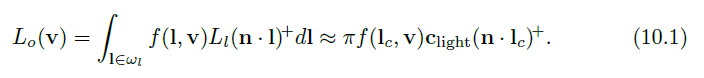
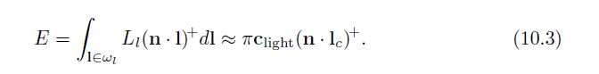
In Chapter 9 we described idealized, infinitesimal light sources: punctual and directional. Figure 10.3 shows the incident hemisphere on a surface point, and the difference between an infinitesimal source and an area light source with a nonzero size. The light source on the left uses the definitions discussed in Section 9.4. It illuminates the surface from a single direction lc. Its brightness is represented by its color clight, defined as the reflected radiance from a white Lambertian surface facing toward the light. The point or directional light’s contribution to the outgoing radiance Lo(v) in direction v is ![]() (note the x+ notation for clamping negative numbers to zero,introduced in Section 1.2). Alternatively, the brightness of the area light source (on the right) is represented by its radiance Ll. The area light subtends a solid angle ωl from the surface location. Its contribution to the outgoing radiance in direction v is the integral of
(note the x+ notation for clamping negative numbers to zero,introduced in Section 1.2). Alternatively, the brightness of the area light source (on the right) is represented by its radiance Ll. The area light subtends a solid angle ωl from the surface location. Its contribution to the outgoing radiance in direction v is the integral of ![]() .
.
在第九章中,我们描述了理想化的、无限小的光源:点光源和定向光源。图10.3显示了表面点上的入射半球,以及无限小光源和非零大小的面光源之间的差异。左侧的光源使用第9.4节中讨论的定义。它从单个方向lc照射表面。它的亮度由它的颜色光来表示,颜色光被定义为从面向光的白色朗伯表面反射的辐射。点光或平行光在方向v上对出射辐射Lo(v)的贡献为![]() (注意第1.2节中介绍的用于将负数钳制为零的x+符号)。可选地,面光源(在右边)的亮度由其辐射Ll表示。区域光对着曲面位置的立体角ωl。它对方向v上的出射辐射的贡献是
(注意第1.2节中介绍的用于将负数钳制为零的x+符号)。可选地,面光源(在右边)的亮度由其辐射Ll表示。区域光对着曲面位置的立体角ωl。它对方向v上的出射辐射的贡献是![]() 。
。
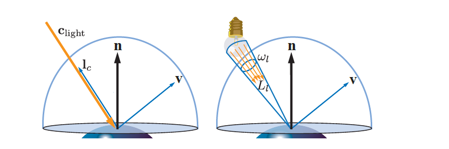
Figure 10.3. A surface illuminated by a light source, considering the hemisphere of possible incoming light directions defined by the surface normal n. On the left, the light source is infinitesimal. On the right, it is modeled as an area light source.
图10.3。由光源照亮的表面,考虑由表面法线n定义的可能入射光方向的半球。在左边,光源是无限小的。在右侧,它被建模为面光源。
The fundamental approximation behind infinitesimal light sources is expressed in the following equation:
无限小光源背后的基本近似值由以下等式表示:
The amount that an area light source contributes to the illumination of a surface location is a function of both its radiance (Ll) and its size as seen from that location (ωl).As we have seen in Section 9.4, point and directional light sources are approximations that cannot be realized in practice since their zero solid angle implies an infinite radiance. Understanding the visual errors that are introduced by the approximation will help to know when to use it, and what approach to take when it cannot be used.These errors will depend on two factors: how large the light source is, measured by the solid angle it covers from the shaded point, and how glossy the surface is.
面光源对表面位置照明的贡献量是其辐射亮度(Ll)和从该位置看的尺寸(ωl)的函数。正如我们在9.4节中所看到的,点光源和定向光源是在实践中无法实现的近似值,因为它们的零立体角意味着无限辐射。理解由近似值引入的视觉误差将有助于知道何时使用它,以及当它不能使用时采取什么方法。这些误差将取决于两个因素:光源有多大,通过它从阴影点覆盖的立体角来测量,以及表面有多光滑。
Figure 10.4 shows how the specular highlight size and shape on a surface depends on both the material roughness and the size of the light source. For a small light source, one that subtends a tiny solid angle compared to the view angle, the error is small. Rough surfaces also tend to show the effect of the light source size less than polished ones. In general, both the area light emission toward a surface point and the specular lobe of the surface BRDF are spherical functions. If we consider the set of directions where the contributions of these two functions are significant, we obtain two solid angles. The determining factor in the error is proportional to the relative size of the emission angle compared to the size of the BRDF specular highlight solid angle.
图10.4显示了镜面高光的大小和形状是如何依赖于材料的粗糙度和光源的大小的。对于与视角相比对着微小立体角的小光源,误差很小。粗糙的表面比抛光的表面更容易显示出光源尺寸的影响。通常,朝向表面点的区域光发射和表面BRDF的镜面波瓣都是球面函数。如果我们考虑这两个函数贡献显著的一组方向,我们得到两个立体角。与BRDF镜面高光立体角的大小相比,误差的决定因素与发射角的相对大小成比例。
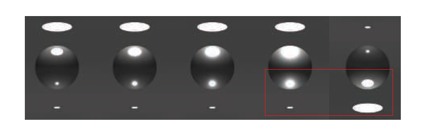
Figure 10.4. From left to right, the material of the sphere increases in surface roughness, using the GGX BRDF. The rightmost image replicates the first in the series, flipped vertically. Notice how the highlight and shading caused by a large disk light on a low-roughness material can look similar to the highlight caused by a smaller light source on a much rougher material.
图10.4。使用GGX BRDF,从左到右,球体材料的表面粗糙度增加。最右边的图像复制了系列中的第一个图像,垂直翻转。请注意,在低粗糙度材质上由大圆盘光源产生的高光和阴影看起来与在粗糙得多的材质上由小光源产生的高光相似。
Finally, note that the highlight from an area light can be approximated by using a punctual light and increasing the surface roughness. This observation is useful for deriving less-costly approximations to the area light integral. It also explains why in practice many real-time rendering system produce plausible results using only punctual sources: Artists compensate for the error. However, doing so is detrimental,as it couples material properties with the particular lighting setup. Content created this way will not look right when the lighting scenario is altered.
最后,请注意,来自区域光的高光可以通过使用点光源和增加表面粗糙度来近似。这种观察对于推导面积光积分的低成本近似是有用的。这也解释了为什么在实践中许多实时渲染系统只使用点源就能产生可信的结果:艺术家补偿了误差。但是,这样做是有害的,因为它将材质属性与特定的照明设置相结合。当照明场景改变时,以这种方式创建的内容将看起来不正确。
For the special case of Lambertian surfaces, using a point light for an area light can be exact. For such surfaces, the outgoing radiance is proportional to the irradiance:
对于Lambertian曲面的特殊情况,使用点光源作为区域光源可能是准确的。对于这种表面,出射辐射与辐照度成正比:
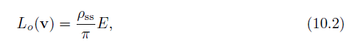
where ρss is the subsurface albedo, or diffuse color, of the surface (Section 9.9.1).This relationship lets us use the equivalent of Equation 10.1 for computing irradiance,which is much simpler:
其中,ρss是表面的次表面反照率或漫射颜色(第9.9.1节)。这种关系使我们可以使用等式10.1的等价物来计算辐照度,这要简单得多:
The concept of vector irradiance is useful to understand how irradiance behaves in the presence of area light sources. Vector irradiance was introduced by Gershun [526], who called it the light vector, and further extended by Arvo [73]. Using vector irradiance, an area light source of arbitrary size and shape can be accurately converted into a point or directional light source.
矢量辐照度的概念有助于理解在存在面光源的情况下辐照度的行为。矢量辐照度由Gershun [526]引入,他称之为光矢量,并由Arvo [73]进一步扩展。使用矢量辐照度,可以将任意大小和形状的面光源精确地转换为点光源或方向光源。
Imagine a distribution of radiance Li coming into a point p in space. See Figure 10.5. We will assume for now that Li is wavelength-independent and thus can be represented as a scalar. For every infinitesimal solid angle dl centered on an incoming direction l, a vector is constructed that is aligned with l and has a length equal to the(scalar) radiance incoming from that direction times dl. Finally, all these vectors are summed to produce the vector irradiance e:
想象入射到空间点p的辐射率Li的分布。参见图10.5。我们现在假设Li与波长无关,因此可以用标量来表示。对于以入射方向l为中心的每个无穷小立体角D1,构造一个向量,该向量与l对齐,并且长度等于从该方向入射的(标量)辐射乘以D1。最后,将所有这些矢量相加以产生矢量辐照度e:
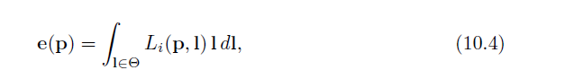
where ![]() indicates that the integral is performed over the entire sphere of directions.
indicates that the integral is performed over the entire sphere of directions.
其中![]() 表示在整个方向球面上进行积分。
表示在整个方向球面上进行积分。
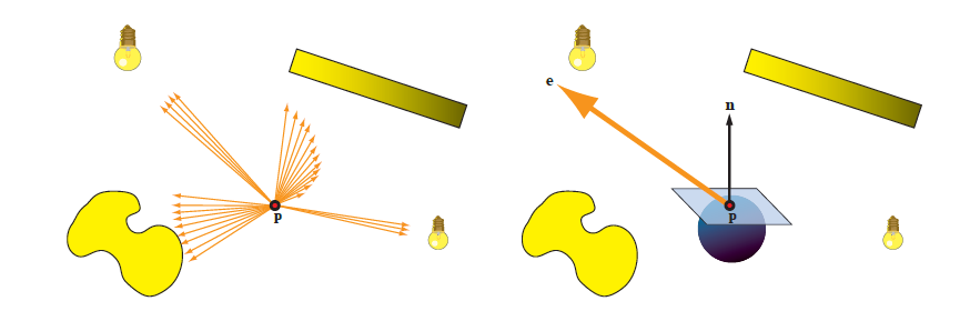
Figure 10.5. Computation of vector irradiance. Left: point p is surrounded by light sources of various shapes, sizes, and radiance distributions. The brightness of the yellow color indicates the amount of radiance emitted. The orange arrows are vectors pointing in all directions from which there is any incoming radiance, and each length is equal to the amount of radiance coming from that direction times the infinitesimal solid angle covered by the arrow. In principle there should be an infinite number of arrows. Right: the vector irradiance (large orange arrow) is the sum of all these vectors.The vector irradiance can be used to compute the net irradiance of any plane at point p.
图10.5。矢量辐照度的计算。左图:点p被各种形状、大小和辐射分布的光源所包围。黄色的亮度表示发射的辐射量。橙色箭头是指向任何入射辐射的所有方向的向量,每个长度等于来自该方向的辐射量乘以箭头覆盖的无穷小立体角。原则上应该有无限个箭头。右图:矢量辐照度(橙色大箭头)是所有这些矢量的总和。矢量辐照度可以用来计算任何平面在p点的净辐照度。
The vector irradiance e can be used to find the net irradiance at p through a plane of any orientation by performing a dot product:
矢量辐照度e可以用来求出p点穿过平面的净辐照度 通过执行点积获得任意方向:
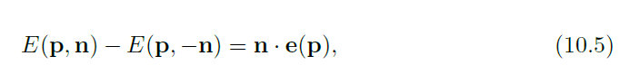
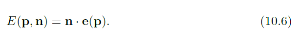
where n is the normal to the plane. The net irradiance through a plane is the difference between the irradiance flowing through the “positive side” of the plane (defined by the plane normal n) and that flowing through the “negative side.” By itself, the net irradiance is not useful for shading. However, if no radiance is emitted through the “negative side” (in other words, the light distribution being analyzed has no parts for which the angle between l and n exceeds 90◦), then E(p,−n) = 0 and
其中n是平面的法线。穿过平面的净辐照度是穿过平面“正侧”的辐照度(由平面法线n定义)和穿过“负侧”的辐照度之差就其本身而言,净辐照度对于着色是没有用的。然而,如果没有辐射从“负侧”发出(换句话说,被分析的光分布没有l和n之间的角度超过90°的部分),则E(p,−n) = 0,并且
The vector irradiance of a single area light source can be used with Equation 10.6 to light Lambertian surfaces with any normal n, as long as n does not face more than 90◦ away from any part of the area light source. See Figure 10.6.
单个面光源的矢量辐照度可用于等式10.6,以任何法线n照射朗伯曲面,只要n与面光源的任何部分的夹角不超过90度。参见图10.6。
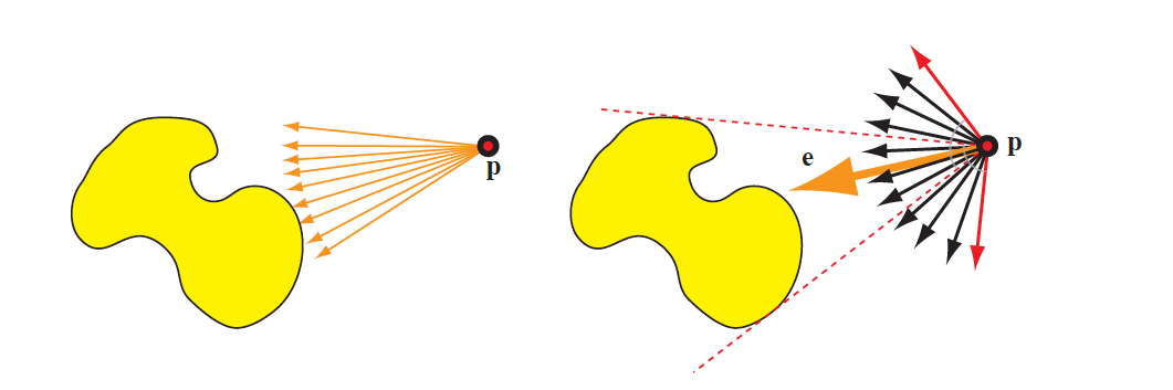
Figure 10.6. Vector irradiance of a single area light source. On the left, the arrows represent the vectors used to compute the vector irradiance. On the right, the large orange arrow is the vector irradiance e. The red dashed lines represent the extent of the light source, and the red vectors (each perpendicular to one of the red dashed lines) define the limits of the set of surface normals. Normals outside this set will have an angle greater than 90◦ with some part of the area light source. Such normals cannot use e to compute their irradiance correctly.
图10.6。单一区域光源的矢量辐照度。在左侧,箭头表示用于计算矢量辐照度的矢量。在右侧,大的橙色箭头是向量辐照度e。红色虚线表示光源的范围,红色向量(每个向量都垂直于红色虚线之一)定义了曲面法线集的限制。该集合之外的法线与区域光源的某个部分的角度大于90度。这种法线不能使用e来正确计算它们的辐照度。
If our assumption that Li is wavelength-independent does not hold, then in the general case we can no longer define a single vector e. However, colored lights often have the same relative spectral distribution at all points, which means that we can factor Li into a color c′ and a wavelength-independent radiance distribution L′i. In this case we can compute e for L′i and extend Equation 10.6 by multiplying n · e by c′. Doing so results in the same equation used to compute the irradiance from a directional light source, with the following substitutions:
如果我们关于Li与波长无关的假设不成立,那么在一般情况下,我们不能再定义单个向量e。然而,彩色光通常在所有点上具有相同的相对光谱分布,这意味着我们可以将Li分解为颜色c’和与波长无关的辐射分布L’I。在这种情况下,我们可以计算L’I的e,并通过将n · e乘以c’来扩展方程10.6。这样做的结果与用于计算定向光源辐照度的等式相同,但有以下替换:
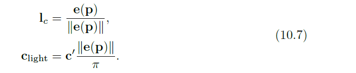
We have effectively converted an area light source of arbitrary shape and size to a directional light source—without introducing any error.
我们已经有效地将任意形状和大小的面光源转换成 定向光源——不会引入任何误差。
Equation 10.4 for finding the vector irradiance can be solved analytically for simple cases. For example, imagine a spherical light source with a center at pl and a radius rl. The light emits a constant radiance Ll from every point on the sphere, in all directions. For such a light source, Equations 10.4 and 10.7 yield the following:
对于简单的情况,方程10.4可以解出矢量辐照度。例如,想象一个球形光源,其中心为P1,半径为R1。光从球体上的每个点向所有方向发出恒定的辐射Ll。对于这种光源,等式10.4和10.7得出以下结果:
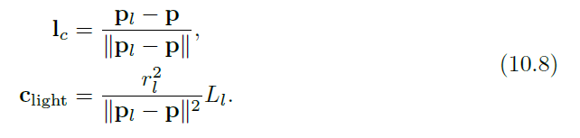
This equation is the same as an omni light (Section 5.2.2) with clight0 = Ll, r0 = rl,and the standard inverse square distance falloff function. This falloff function can be adjusted to account for points inside the sphere, and to bound the light influence to a given maximum distance. More details on such adjustments can be found in Section 5.2.2.
该等式与clight0 = Ll,r0 = rl的泛光灯(第5.2.2节)以及标准的平方距离倒数falloff函数相同。可以调整该衰减函数,以考虑球体内部的点,并将灯光影响限制在给定的最大距离。有关此类调整的更多详细信息,请参见第5.2.2节。
All this is correct only if there is no “negative side” irradiance. Another way to think about it is that no parts of the area light source can be “under the horizon,” or occluded by the surface. We can generalize this statement. For Lambertian surfaces,all disparities between area and point light sources result from occlusion differences.The irradiance from a point light source obeys a cosine law for all normals for which the light is not occluded. Snyder derived an analytic expression for a spherical light source, taking occlusion into account [1671]. This expression is quite complex. However, since it depends on only two quantities (r/rl and θi, the angle between n and lc), it can be precomputed into a two-dimensional texture. Snyder also gives two functional approximations that are amenable for real-time rendering.
所有这些只有在没有“负面”辐照度的情况下才是正确的。另一种思考方式是,区域光源的任何部分都不能“在地平线下”,也不能被表面遮挡。我们可以概括这种说法。对于朗伯曲面,面光源和点光源之间的所有差异都是由遮挡差异造成的。对于光线未被遮挡的所有法线,点光源的辐照度遵循余弦定律。Snyder推导出一个球形光源的解析表达式,考虑了遮挡[1671]。这个表达式相当复杂。但是,由于它只取决于两个量(r/rl和θi,n和lc之间的角度),因此可以预先计算到二维纹理中。Snyder也给出了两种适用于实时渲染的函数逼近。
In Figure 10.4 we saw that the effects of area lighting are less noticeable for rough surfaces. This observation allows us also to use a less physically based but still effective method for modeling the effects of area lights on Lambertian surfaces: wrap lighting.In this technique, some simple modification is done to the value of n · l before it is clamped to 0. One form of wrap lighting is given by Forsyth [487]:
在图10.4中,我们看到粗糙表面的区域照明效果不太明显。这种观察还允许我们使用一种物理基础较弱但仍然有效的方法来模拟区域光在朗伯曲面上的效果:包裹照明。在这种技术中,在n · l 的值被箝位到0之前,对其进行一些简单的修改。Forsyth [487]给出了包裹照明的一种形式:
where kwrap ranges from 0, for point light sources, to 1, for area light sources covering the entire hemisphere. Another form that mimics the effect of a large area light source is used by Valve [1222]:
其中kwrap的范围从0(代表点光源)到1(代表覆盖整个半球的面光源)。模拟大面积光源效果的另一种形式由阀[1222]使用:
In general, if we compute area lighting, we should also modify our shadowing computations to take into account a non-punctual source. If we do not, some of the visual effect can be canceled out by the harsh shadows [193]. Soft shadows are perhaps the most visible effect of area light sources, as discussed in Chapter 7.
一般来说,如果我们计算区域照明,我们也应该修改我们的阴影计算来考虑非正点光源。如果我们不这样做,一些视觉效果会被强烈的阴影抵消掉[193]。正如第七章所讨论的,柔和的阴影可能是面光源最明显的效果。


 5580
5580


 被折叠的 条评论
为什么被折叠?
被折叠的 条评论
为什么被折叠?
 到【灌水乐园】发言


