


 文章介绍了使用CC2530开发板通过C语言实现的几个项目,包括基本LED灯控制、跑马灯效果、单按键和多按键控制灯光开关,以及按键电子计数器和跑马灯启动暂停功能。

代码+注释:
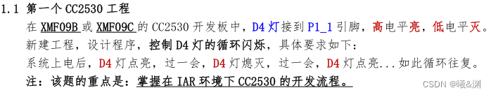
1-第一个CC2530工程(新建工程请参考【物联网技能竞赛】ZigBee点亮Led入门笔记)
#include "ioCC2530.h"//引入头文件
#define D4 P1_1//宏定义D4灯的引脚
void Init_port(){
P1SEL &= ~0x02;//将 P1_1 设置成通用I/O功能
P1DIR |= 0x02;//将 P1_1 设置成输出模式
P1 &= ~0x02;//将P1_1设置成低电平
}
void Delay(unsigned int t)
{
while(t--);//空循环
}
void main()
{
Init_port();//初始化P1_1引脚
while(1)
{
D4=1;//将P1_1设置成高电平
Delay(0xffff);//延时函数
D4=0;//将P1_1设置成低电平
Delay(0xffff);//延时函数
}
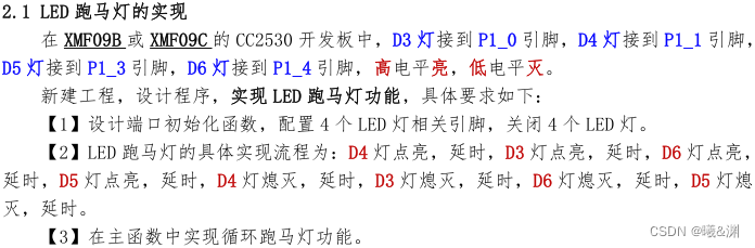
}02-LED 跑马灯的实现
#include "ioCC2530.h"
#define D3 P1_0//宏定义D3灯的引脚
#define D4 P1_1//宏定义D4灯的引脚
#define D5 P1_3//宏定义D5灯的引脚
#define D6 P1_4//宏定义D6灯的引脚
void Delay(unsigned int t)
{
while(t--);//空循环
}
void Init_port()
{
P1SEL &= ~0x1B;//将P1_0 P1_1 P1_3 P1_4设置成通用I/O功能
P1DIR |= 0x1B;//将P1_0 P1_1 P1_3 P1_4设置成输出模式
P1 &= ~0x1B;//将P1_0 P1_1 P1_3 P1_4设置成低电平
}
void run_led()
{
D4=1;//将P1_1设置成高电平
Delay(0xffff);//延时
D3=1;//将P1_0设置成高电平
Delay(0xffff);//延时
D6=1;//将P1_4设置成高电平
Delay(0xffff);//延时
D5=1;//将P1_3设置成高电平
Delay(0xffff);//延时
D4=0;//将P1_1设置成低电平
Delay(0xffff);//延时
D3=0;//将P1_0设置成低电平
Delay(0xffff);//延时
D6=0;//将P1_4设置成低电平
Delay(0xffff);//延时
D5=0;//将P1_3设置成低电平
Delay(0xffff);//延时
}
void main()
{
Init_port();//初始化LED灯引脚
while(1)
{
run_led();//跑马灯
}
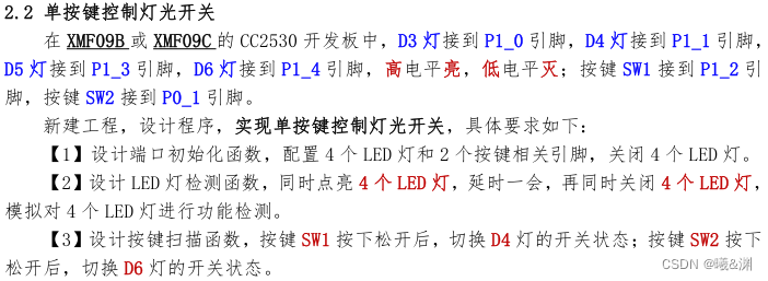
}03-单按键控制灯光开关
#include "ioCC2530.h"
//按钮和LED灯引脚映射
#define D3 P1_0
#define D4 P1_1
#define D5 P1_3
#define D6 P1_4
#define SW1 P0_1
#define SW2 P1_2
void Delay(unsigned int t)//延时函数
{
while(t--);
}
void Init_port()//初始化端口引脚
{
//初始化LED灯
P1SEL &= ~0X1b;//将所有LED引脚初始化成通用I/O模式
P1DIR |= 0x1b;//将所有LED引脚初始化成输出模式
P1 &= ~0x1b;//将所有LED引脚设置成低电平
P1SEL &= ~0x04;//将SW2引脚初始化成通用I/O模式
P1DIR &= ~0x04;//将SW2引脚初始化成输入模式
P1INP &= ~0x04;//将SW2引脚初始化成上拉模式
P2INP &= ~0x40;//将P1端口设置成上拉/下拉
P0SEL &= ~0x02;//将SW2引脚初始化成通用I/O模式
P0DIR &= ~0x02;//将SW2引脚初始化成输入模式
P0INP &= ~0x02;//将SW2引脚初始化成上拉模式
P2INP &= ~0x20;//将P0端口设置成上拉/下拉
}
void check_led()
{
P1 |= 0x1B;//将所有LED引脚设置成高电平
Delay(0xffff);//延时
Delay(0xffff);
Delay(0xffff);
Delay(0xffff);
P1 &= ~0x1B;//将所有LED引脚设置成低电平
}
void key()
{
if(SW1==0)//SW1是否为按下状态
{
Delay(50);//延时去抖
if(SW1==0)//再次判断
{
while(SW1==0);//等待松开
D4 = ~D4;//反转
}
}
if(SW2==0)//SW2是否为按下状态
{
Delay(50);//延时去抖
if(SW2==0)//再次判断
{
while(SW2==0);//等待松开
D6 = ~D6;//反转
}
}
}
void main()
{
Init_port();
check_led();
while(1)
{
key();
}
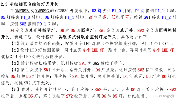
}04-多按键联合控制灯光开关
#include "ioCC2530.h"
//LED灯和按钮引脚的映射
#define D3 P1_0
#define D4 P1_1
#define D5 P1_3
#define D6 P1_4
#define SW1 P1_2
#define SW2 P0_1
unsigned int status=0;
unsigned int led_status=0;
void Delay(unsigned int t)//延时函数
{
while(t--);
}
void Init_port()//初始化端口引脚
{
//初始化LED灯
P1SEL &= ~0X1b;//将所有LED引脚初始化成通用I/O模式
P1DIR |= 0x1b;//将所有LED引脚初始化成输出模式
P1 &= ~0x1b;//将所有LED引脚设置成低电平
P1SEL &= ~0x04;//将SW2引脚初始化成通用I/O模式
P1DIR &= ~0x04;//将SW2引脚初始化成输入模式
P1INP &= ~0x04;//将SW2引脚初始化成上拉模式
P2INP &= ~0x40;//将P1端口设置成上拉/下拉
P0SEL &= ~0x02;//将SW2引脚初始化成通用I/O模式
P0DIR &= ~0x02;//将SW2引脚初始化成输入模式
P0INP &= ~0x02;//将SW2引脚初始化成上拉模式
P2INP &= ~0x20;//将P0端口设置成上拉/下拉
}
void check_led()//检查LED灯函数
{
P1 |= 0x1b;
Delay(0xffff);
Delay(0xffff);
P1 &= ~0x1b;
Delay(0xffff);
Delay(0xffff);
}
void key()
{
if(SW1==0)//SW1是否为按下状态
{
Delay(50);//延时去抖
if(SW1==0)//再次判断
{
while(SW1==0);//等待松开
if(status==0)//总开关是否为关闭状态
{
//打开
D4=1;
status=1;
}else//总开关是否为打开状态
{
//关闭
status=0;
D4=0;
D5=0;
D6=0;
led_status=0;
}
}
}
if(status==1){//总开关打开的状态才检查
if(SW2==0)//SW1是否为按下状态
{
Delay(50);//延时去抖
if(SW2==0)//再次判断
{
while(SW2==0);//等待松开
if(led_status==0)
{
D5=1;//第一次按下
}else if(led_status==1)
{
D6=1;//第二次按下
}else
{
//第三次按下
D5=0;
D6=0;
}
//改变led_status的状态值
if(led_status==2)
{
led_status=0;
}else
{
led_status++;
}
}
}
}
}
void main()
{
Init_port();
check_led();
while(1)
{
key();
}
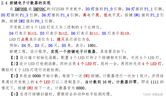
}05-按键电子计数器的实现
#include "ioCC2530.h"
//LED灯和按钮引脚的映射
#define D3 P1_0
#define D4 P1_1
#define D5 P1_3
#define D6 P1_4
#define SW1 P1_2
#define SW2 P0_1
unsigned int count=0;
void Init_port()//初始化端口引脚
{
//初始化LED灯
P1SEL &= ~0X1b;//将所有LED引脚初始化成通用I/O模式
P1DIR |= 0x1b;//将所有LED引脚初始化成输出模式
P1 &= ~0x1b;//将所有LED引脚设置成低电平
P1SEL &= ~0x04;//将SW2引脚初始化成通用I/O模式
P1DIR &= ~0x04;//将SW2引脚初始化成输入模式
P1INP &= ~0x04;//将SW2引脚初始化成上拉模式
P2INP &= ~0x40;//将P1端口设置成上拉/下拉
P0SEL &= ~0x02;//将SW2引脚初始化成通用I/O模式
P0DIR &= ~0x02;//将SW2引脚初始化成输入模式
P0INP &= ~0x02;//将SW2引脚初始化成上拉模式
P2INP &= ~0x20;//将P0端口设置成上拉/下拉
}
void Delay(unsigned int t)//延时函数
{
while(t--);
}
void check_led()//检查LED灯函数
{
P1 |= 0x1b;
Delay(0xffff);
Delay(0xffff);
P1 &= ~0x1b;
Delay(0xffff);
Delay(0xffff);
}
void led_02()
{
if((count & 0x08) == 0x08)
{
D4=1;
}
if((count & 0x04) == 0x04)
{
D3=1;
}
if((count & 0x02) == 0x02)
{
D6=1;
}
if((count & 0x01) == 0x01)
{
D5=1;
}
}
void led_01()
{
if((count/8)==1)//判断第三位是否为1---比如:(9/8)=1
{
D4=1;
}
if(((count%8)/4)==1)//判断第2位是否为1---比如:((9%8)/4)= 0
{
D3=1;
}
if((((count%8)%4)/2)==1)//判断第1位是否为1---比如:(((9%8)%4)/2)= 0
{
D6=1;
}
if(((((count%8)%4)%2)/1)==1)//判断第0位是否为1------比如:((((9%8)%4)%2)/1)= 0
{
D5=1;
}
}
void key()
{
if(SW1==0)//SW1是否为按下状态
{
Delay(50);//延时去抖
if(SW1==0)//再次判断
{
while(SW1==0);//等待松开
if(count==16)//重新
{
count=0;
}
//全部熄灭
D3=0;
D4=0;
D5=0;
D6=0;
count++;//改变值
led_02();
}
}
}
void main()
{
Init_port();
check_led();
while(1)
{
key();
}
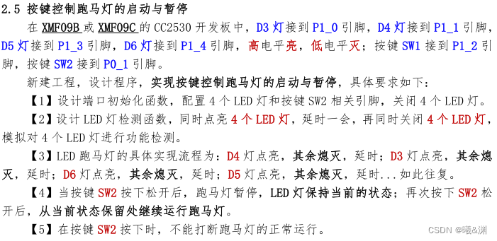
}06-按键控制跑马灯的启动与暂停
#include "ioCC2530.h"
//LED灯和按钮引脚的映射
#define D1 P1_0
#define D2 P1_1
#define D3 P1_3
#define D4 P1_4

#define SW1 P1_2
#define SW2 P0_1

void Init_port()//初始化LED灯和按钮
{
  P1SEL &= ~0x1F;    //0001 1111     设置所有的端口为I/O功能

  P1DIR |= 0x1B;     //0001 1011     将D1,D2,D3,D4设为输出

  P1DIR &= ~0x04;   //0000 0100      将SW1设为输入
  P0DIR &= ~0x02;   //0000 0010      将SW2设为输入

  P1INP &= ~0x04;   //将SW1设置为上拉/下拉
  P0INP &= ~0x02;   //将SW2设置为上拉/下拉

  P2INP &= ~0x60;   //将P1和P0端口设置为上拉

  P1 &= ~0x1B;
}

unsigned int F=1;//是否暂停跑马灯的标志位
unsigned int count=0;//计数值
void Delay(unsigned int t)//延时函数
{
  while(t--);
}
void checkLED()//检查灯
{
  P1 |= 0x1B;
  Delay(0xffff);
  Delay(0xffff);
  Delay(0xffff);
  P1 &= ~0x1B;
  Delay(0xffff);
  Delay(0xffff);
  Delay(0xffff);
}
void key()
{
  if(SW2==0)//SW1是否为按下状态
  {
    Delay(20);//延时去抖
    if(SW2==0)//再次判断
    {
      while(SW2==0);//等待松开
      F =~F;//反转标志位
    }
  }
}

void liuLED()//灯
{
   Delay(20);//切片延时
   if(F==1){ count++;}//运行跑马灯时,累加以达到改变灯的状态
   if(count<1500)//延时1500*20=30000
   {
        D1=1;
        D2=0;
        D3=0;
        D4=0;
   }else if(count<3000)
   {
        D1=0;
        D2=1;
        D3=0;
        D4=0;
   }else if(count<4500)
   {
        D1=0;
        D2=0;
        D3=1;
        D4=0;
   }else if(count<6000)
   {
        D1=0;
        D2=0;
        D3=0;
        D4=1;
   }else
   {
     count=0;
   }
}

void main()
{
  Init_port();
  checkLED();
  while(1)
  {
    liuLED();
     key();
  }
}
代码如上(工程文件已上传,可下载),感谢观看。


 960
960


 被折叠的 条评论
为什么被折叠?
被折叠的 条评论
为什么被折叠?
 到【灌水乐园】发言


