


目录
实验目标及任务
实验目的:
1、深入了解单周期CPU中指令控制器的结构和工作原理。
2、学习使用Verilog HDL设计实现单周期CPU中指令控制器。
实验任务:
1、设计和实现单周期CPU中指令控制器的结构并且进行功能仿真。
实验内容与结果记录
源代码:
//根据机器码操作,控制各个信号
module SCPU_ctrl(
    input[5:0] OPcode,    //OPcode
    input[5:0] func,      //function
    output wire RegDst,
    output wire ALUSrc_B,
    output wire MemtoReg,
    output wire Jump,
    output wire Branch,
    output wire RegWrite,
    output wire[2:0] ALU_Control,
    output wire MemRead,
    output wire MemWrite
    );
    wire R_format,LW,SW,Beq;
    assign R_format=~(OPcode[5] | OPcode[4] | OPcode[3] | OPcode[2] | OPcode[1] | OPcode[0]);//000000
    assign LW=(OPcode[5] & ~OPcode[3] & ~OPcode[2] & OPcode[1] & OPcode[0]);//1x0011
    assign SW=(OPcode[5] & OPcode[3] & ~OPcode[2] & OPcode[1] & OPcode[0]);//1x1011
    assign Beq=(~OPcode[5] & ~OPcode[3] & OPcode[2] & ~OPcode[1] & ~OPcode[0]);//0x0100

    assign Branch=Beq;
    assign RegWrite=( R_format | LW );
    assign RegDst=R_format;
    assign MemtoReg=LW;
    assign ALUSrc_B=( SW | LW );
    assign MemWrite=SW;
    assign Jump=(~OPcode[5] & ~OPcode[3] & ~OPcode[2] & OPcode[1] & ~OPcode[0]);//0x0010
    assign MemRead=LW;

    wire ALUop0,ALUop1;//控制器输入操作码
    buf b0(ALUop0,Beq);
    buf b1(ALUop1,R_format);

    wire A1,AB1,O1,N_FUNC1;
    and AND1(A1 , ALUop1 , func[1]);
    not N1( N_FUNC1, func[1] );
    and AND2B1( AB1, func[0], N_FUNC1 );
    or OR1( O1, AB1, func[3] );
    or OR2( ALU_Control[2], ALUop0, A1 );
    nand NAND2( ALU_Control[1], ALUop1, func[2] );
    and AND2( ALU_Control[0], ALUop1, O1 );

endmodule


//读取文件,获取机器码
module instruction_memory (
    input [31:0] address,
    output reg [31:0] instruction//作用是提供opcode和func
    );
    reg [31:0] memoryy [255:0]; // 假设指令存储器大小为256条指令
    initial begin
        $readmemh("D:/Vivado projects/EXP8_0/instruction.txt", memoryy);
        instruction =1;
    end

    always @(address) begin
        instruction = memoryy[address[31:2]]; // 按字对齐
    end
endmodule


//总调用
module top (
    input [8:0] addresssw,//开关信号控制address
    /*
    input [5:0] opcode,//这两个后面改成addresssw,调用instructionmemory来赋值opcode,调用scpu
    input [5:0] func,
    */
    output [10:0] leds
    );
    reg [31:0] address;
    wire [31:0] instruction;
    always @(*)begin
        case(addresssw)
            9'b100000000: address=32'h00;
            9'b010000000: address=32'h04;
            9'b001000000: address=32'h08;
            9'b000100000: address=32'h0c;
            9'b000010000: address=32'h10;
            9'b000001000: address=32'h14;
            9'b000000100: address=32'h18;
            9'b000000010: address=32'h1c;
            9'b000000001: address=32'h20;
    endcase
    end
    instruction_memory im(
        .address(address),
        .instruction(instruction)
    );

    wire RegDst, ALUSrc_B, MemtoReg, Jump, Branch, RegWrite, MemRead, MemWrite;
    wire [2:0] ALU_Control;

    SCPU_ctrl ctrl (
        .OPcode(instruction[31:26]),
        .func(instruction[5:0]),
        .RegDst(RegDst),
        .ALUSrc_B(ALUSrc_B),
        .MemtoReg(MemtoReg),
        .Jump(Jump),
        .Branch(Branch),
        .RegWrite(RegWrite),
        .ALU_Control(ALU_Control),
        .MemRead(MemRead),
        .MemWrite(MemWrite)
    );

    assign leds[0] = Jump;
    assign leds[1] = Branch;
    assign leds[2] = MemWrite;
    assign leds[3] = MemRead;
    assign leds[4] = RegWrite;
    assign leds[5] = MemtoReg;
    assign leds[6] = ALUSrc_B;
    assign leds[7] = RegDst;
    assign leds[8] = ALU_Control[0];
    assign leds[9] = ALU_Control[1];
    assign leds[10] = ALU_Control[2];
    // 其余的LED信号可以根据需要连接
endmodule
激励文件:
module testbench;

    // Inputs
    reg [8:0] addresssw;
    wire [10:0] leds;


    // Instantiate the top module
    top uut_top (
        .addresssw(addresssw),
        .leds(leds)
    );

    initial begin
        // Initialize Inputs
        addresssw=9'b100000000;
        #10;
        addresssw= 9'b010000000;
        #10;
        addresssw=9'b001000000;
        #10;
        addresssw=9'b000100000;
        #10;
        $finish;
    end

endmodule
引脚约束文件:
set_property PACKAGE_PIN P5 [get_ports {addresssw[8]}]
set_property PACKAGE_PIN P4 [get_ports {addresssw[7]}]
set_property PACKAGE_PIN P3 [get_ports {addresssw[6]}]
set_property PACKAGE_PIN P2 [get_ports {addresssw[5]}]
set_property PACKAGE_PIN R2 [get_ports {addresssw[4]}]
set_property PACKAGE_PIN M4 [get_ports {addresssw[3]}]
set_property PACKAGE_PIN N4 [get_ports {addresssw[2]}]
set_property PACKAGE_PIN R1 [get_ports {addresssw[1]}]
set_property PACKAGE_PIN U3 [get_ports {addresssw[0]}]

set_property PACKAGE_PIN F6 [get_ports {leds[10]}]
set_property PACKAGE_PIN G4 [get_ports {leds[9]}]
set_property PACKAGE_PIN G3 [get_ports {leds[8]}]
set_property PACKAGE_PIN J4 [get_ports {leds[7]}]
set_property PACKAGE_PIN H4 [get_ports {leds[6]}]
set_property PACKAGE_PIN J3 [get_ports {leds[5]}]
set_property PACKAGE_PIN J2 [get_ports {leds[4]}]
set_property PACKAGE_PIN K2 [get_ports {leds[3]}]
set_property PACKAGE_PIN K1 [get_ports {leds[2]}]
set_property PACKAGE_PIN H6 [get_ports {leds[1]}]
set_property PACKAGE_PIN H5 [get_ports {leds[0]}]

set_property IOSTANDARD LVCMOS33 [get_ports {addresssw[8]}]
set_property IOSTANDARD LVCMOS33 [get_ports {addresssw[7]}]
set_property IOSTANDARD LVCMOS33 [get_ports {addresssw[6]}]
set_property IOSTANDARD LVCMOS33 [get_ports {addresssw[5]}]
set_property IOSTANDARD LVCMOS33 [get_ports {addresssw[4]}]
set_property IOSTANDARD LVCMOS33 [get_ports {addresssw[3]}]
set_property IOSTANDARD LVCMOS33 [get_ports {addresssw[2]}]
set_property IOSTANDARD LVCMOS33 [get_ports {addresssw[1]}]
set_property IOSTANDARD LVCMOS33 [get_ports {addresssw[0]}]

set_property IOSTANDARD LVCMOS33 [get_ports {leds[10]}]
set_property IOSTANDARD LVCMOS33 [get_ports {leds[9]}]
set_property IOSTANDARD LVCMOS33 [get_ports {leds[8]}]
set_property IOSTANDARD LVCMOS33 [get_ports {leds[7]}]
set_property IOSTANDARD LVCMOS33 [get_ports {leds[6]}]
set_property IOSTANDARD LVCMOS33 [get_ports {leds[5]}]
set_property IOSTANDARD LVCMOS33 [get_ports {leds[4]}]
set_property IOSTANDARD LVCMOS33 [get_ports {leds[3]}]
set_property IOSTANDARD LVCMOS33 [get_ports {leds[2]}]
set_property IOSTANDARD LVCMOS33 [get_ports {leds[1]}]
set_property IOSTANDARD LVCMOS33 [get_ports {leds[0]}]
模拟仿真图像:

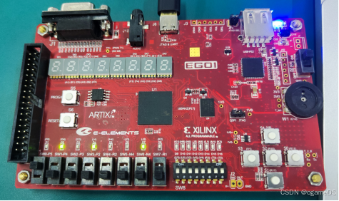
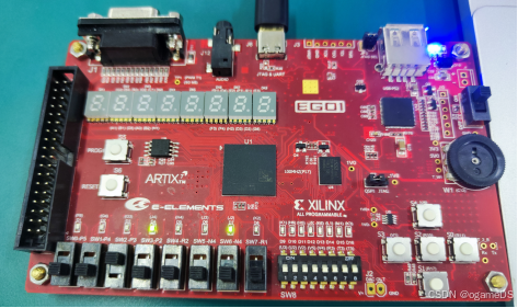
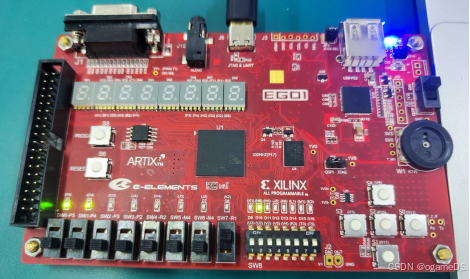
下载到开发板上的图片结果:
本次实验中需要注意的部分:
实验需要了解verilog的文件操作,学习readmemh的使用方法。
会注意到“文件内容只应该有空白符(或换行、空格符)、二进制或十六进制数据,注释用"//"进行标注,数据间建议用换行符区分”,这是我重写instruction.txt机器码文件的原因;我读出文件内容使用的是绝对路径(在“源代码”第76行),使用时要注意修改。
地址对应的指令则需要的instruction.txt文件我自己重写后内容如下:
00000020 //add 000000 xx xxxx xxxx xxxx xxxx xx 100000 该文本中x全当0处理
00000022 //sub 000000 xx xxxx xxxx xxxx xxxx xx 100010
00000024 //and 000000 xx xxxx xxxx xxxx xxxx xx 100100
00000025 //or 000000 xx xxxx xxxx xxxx xxxx xx 100101
0000002a //sll 000000 xx xxxx xxxx xxxx xxxx xx 101010
8c000000 //LW 100011 xx xxxx xxxx xxxx xxxx xx xxxxxx
ac000000 //SW 101011 xx xxxx xxxx xxxx xxxx xx xxxxxx
10000000 //BEQ 000100 xx xxxx xxxx xxxx xxxx xx xxxxxx
08000000 //JUMP 000010 xx xxxx xxxx xxxx xxxx xx xxxxxx


 2492
2492

 被折叠的 条评论
为什么被折叠?
被折叠的 条评论
为什么被折叠?
 到【灌水乐园】发言


