


S32K14X_CAN2.0_RxFIFO_driver
S32K14X CAN2.0收发数据帧配置(no SDK)
1、工作原理


When MCR[RFEN] is set, the memory area from 0x80 to 0xDC (which is normally
occupied by MBs 0–5) is used by the reception FIFO engine.
The region 0x80-0x8C contains the output of the FIFO which must be read by the CPU as
a message buffer. This output contains the oldest message that has been received but not
yet read. The region 0x90-0xDC is reserved for internal use of the FIFO engine.
我们从Rx FIFO架构看出,CAN2.0帧使用滤波模式接收,1MB(message buffer)占用4word,每个word对应4byte。其中前面2个word表示长度、时间戳、IDE、RTR、CAN ID等信息,后2个word表示CAN数据段8byte。所以在RAM Message Buffers分配时,MB0作为存放帧头和数据域,MB1~MB5 被保留给FIFO引擎的内部使用。MB6-MB7默认是CAN ID过滤表元素0-1,MB8-MB37是可配置ID过滤表元素2-127,至于ID 过滤表元素组的分配由CTRL2[RFFN]值决定,具体见下表。

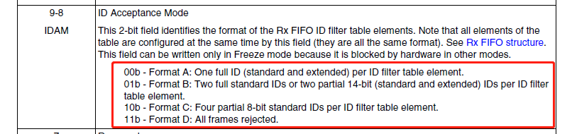
这里再谈谈ID table elements formats,总共三种elements formats,具体格式由MCR[IDAM]值决定(下面例程选用Format A),见下图。

2、代码编写
FlexCAN initialization sequence


/*
 * ===================================================
 * Function :  FLEXCAN0_init For Classical CAN2.0
 * 1. CAN configuration, set baud rate = 500Kbps
 * 2. @note CAN Baud rate calculation
 *    Tq = (PRESDIV + 1) / f_canclk = 1 / 8M
 *    1 CAN Bit Time = (1 + (PROPSEG + PSEG1 + 2) + (PSEG2 + 1)) * Tq
 *    = (1 + (6 + 3 + 2) + (3 + 1) * 1/8M
 *    = 16 * 1/8M = 2us
 *    Baud Rate = 1/2us = 500Kbps
 * 3. configure 1MB = 8 CAN->RAMn = 32byte
 * 4. MB6 ~ FIFO Rx
 * 5. FIFO receives interrupt
 * 6. disable frame self reception
 * 7. RFFN = 2,ID filter table = 2*8+8 = 24
 * 8. ID Acceptance Mode = Format A:
 * Coder :  djf
 * Date/Time :  2020/07/01
 * ===================================================
 */

#define MSG_BUF_SIZE        4u    /* 1 Msg Buffer Size : CAN0->RAMn[i] use 4word(1word=4byte). 4word = 2word header, 2word Data*/
#define MB_FIFO_NUM         6u    /* MB Size used for FIFO engine: MB0~5 */
#define MB_FIFO_IDX_RX      6u    /* MB for receiving CAN message*/

void FLEXCAN0_init(void)                   //Classical
{
    uint32_t i = 0;

    PCC->PCCn[PCC_FlexCAN0_INDEX] |= PCC_PCCn_CGC_MASK; /* CGC=1: enable clock to FlexCAN0 */

    CAN0->MCR |= CAN_MCR_SOFTRST_MASK;      //Soft Reset
	CAN0->MCR &= ~CAN_MCR_SOFTRST_MASK;

    CAN0->MCR |= CAN_MCR_MDIS_MASK;         /* MDIS=1: Disable module before selecting clock */
    CAN0->CTRL1 &= ~CAN_CTRL1_CLKSRC_MASK;  /* CLKSRC=0: Clock Source = oscillator (8 MHz) */
    CAN0->MCR &= ~CAN_MCR_MDIS_MASK;        /* MDIS=0; Enable the FlexCAN module. (Sets FRZ, HALT)	*/
    // After the clock source is selected and the module is enabled (MCR[MDIS] bit negated), FlexCAN automatically enters Freeze mode. In Freeze mode
    // CAN0->MCR |= CAN_MCR_FRZ_MASK;          /*(Sets FRZ, HALT)	*/
    while (!((CAN0->MCR & CAN_MCR_FRZACK_MASK) >> CAN_MCR_FRZACK_SHIFT)) {}

    // Step1: Initialize MCR
    CAN0->MCR |= CAN_MCR_IRMQ_MASK // a: IRMQ=1, enable the individual filtering per MB and reception queue features
              | CAN_MCR_WRNEN_MASK // b: WRNEN=1, enable the warning interrupts
              | CAN_MCR_SRXDIS_MASK // c: SRXDIS=1, disable frame self reception
              | CAN_MCR_RFEN_MASK // d: RFEN=1, Enable the Rx FIFO, MBs 0 to 5 cannot be used for normal reception and transmission(they have been uesed for the FIFO engine)
              // e: DMA=0, dont use DMA
              // f: PNET_EN=0, dont use pretended networking
              | CAN_MCR_AEN_MASK// g: AEN=1, use Tx Abort mechanism
              | CAN_MCR_LPRIOEN_MASK   // h: PRIOEN=1, Local Priority enabled
              | CAN_MCR_IDAM(0)// IDAM=0, ID Acceptance Mode=Format A: One full ID (standard and extended) per ID filter table element.
              | CAN_MCR_MAXMB(32); // MAXMB = Rx FIFO + ID filter table space(CTRL2[REFN]), default=16

    // Step2: Initialize CTRL1 or CBT
    // The CAN bit variables in CTRL1 and in CBT are stored in the same register.
    // Configure for CAN bit rate = 500 Kbps, 16 time quanta for 1 bit
    CAN0->CTRL1 |= CAN_CTRL1_PRESDIV(0)  // Tq = fcanclk / prediv = 8MHz / 1 = 8MHz
                | CAN_CTRL1_RJW(3)  // RJW: since Phase_Seg2 >=4, RJW+1=4 so RJW=3.
                | CAN_CTRL1_PSEG1(3)  // Phase Segment 1 = PSEG1 + 1
                | CAN_CTRL1_PSEG2(3)  // Phase Segment 2 = PSEG2 + 1
                | CAN_CTRL1_PROPSEG(6)  // Propagation Segment = PROPSEG + 1
                | CAN_CTRL1_SMP(1)
                | CAN_CTRL1_LBUF(1);   // LBUF=1, Lowest number buffer is transmitted first.(MCR[LPRIOEN] + LBUF <= transmit priority)

    // Step3: Initialize the message buffers
    // MB & Rx Individual Mask registers are not affected by reset, so they are not initialized automatically.
    // payload=8, MB0~5 used for FIFO engine(contains message received but not read)
    // CAN0: clear 32 message buffer x 4 words/msg, buf = 128 words
    // CAN0 contains 32MBs
    for(i=24; i<128; i++)   //i = Number of Rx FIFO filter elements; Table 53-6. Rx FIFO filter: possible structures
    {   					 /* CAN0: clear 32 msg bufs x 4 words/msg buf = 128 words */
        CAN0->RAMn[i] = 0;   /* Clear msg buf word */
    }
    // set the ID Table, assuming CTRL2[RFFN=2]     //2. Write the ID word
    CAN0->RAMn[MB_FIFO_NUM*MSG_BUF_SIZE + 0] = (0x55 &0x7FF) << 19; // ID filter table element 0
    CAN0->RAMn[MB_FIFO_NUM*MSG_BUF_SIZE + 1] = ((0x0F000F56&0x1FFFFFFF) << 1) | 0x40000000; // element 1 IDE=1 EXT id
    CAN0->RAMn[MB_FIFO_NUM*MSG_BUF_SIZE + 2] = (0x57 &0x7FF) << 19; // element 2
    CAN0->RAMn[MB_FIFO_NUM*MSG_BUF_SIZE + 3] = (0x58 &0x7FF) << 19; // element 3

    CAN0->RAMn[MB_FIFO_NUM*MSG_BUF_SIZE + 4] = ((0x59 &0x7FF) << 19) | 0x80000000; // element 4 RTR=1
    CAN0->RAMn[MB_FIFO_NUM*MSG_BUF_SIZE + 5] = (0x5A &0x7FF) << 19; // element 5
    CAN0->RAMn[MB_FIFO_NUM*MSG_BUF_SIZE + 6] = (0x5B &0x7FF) << 19; // element 6
    CAN0->RAMn[MB_FIFO_NUM*MSG_BUF_SIZE + 7] = (0x5C &0x7FF) << 19; // element 7

    CAN0->RAMn[MB_FIFO_NUM*MSG_BUF_SIZE + 8] = (0x60 &0x7FF) << 19; // element 8
    CAN0->RAMn[MB_FIFO_NUM*MSG_BUF_SIZE + 9] = (0x61 &0x7FF) << 19; // element 9
    CAN0->RAMn[MB_FIFO_NUM*MSG_BUF_SIZE + 10] = (0x62 &0x7FF) << 19; // element 10
    CAN0->RAMn[MB_FIFO_NUM*MSG_BUF_SIZE + 11] = (0x63 &0x7FF) << 19; // element 11
    CAN0->RAMn[0] |= CAN_WMBn_CS_CODE(0x04);         //3. Write the EMPTY code (0b0100) to the CODE field, activate the mailbox

    // Step4: Initialize RXIMRn(Rx Individual Mask registers)
    // In FRZ mode, init CAN0 16 individual msg buf filters . there are total 32MBs for CAN0
    for(i=0; i<32; i++ )           /* the mailbox filter and Rx FIFO ID filter table element in distinct ways.*/
    {
        CAN0->RXIMR[i] = 0xFFFFFFFF;  	/* 1b - The corresponding bit in the filter is checked. 0b-The corresponding bit in the filter is "don't care." */
    }
    CAN0->RXMGMASK = 0x1FFFFFFF;  				/* Mailboxes Global Mask. Global acceptance mask: check all ID bits 	*/
                                                /* 1b - The corresponding bit in the filter is checked. 0b-The corresponding bit in the filter is "don't care." */
    CAN0->RX14MASK = 0x1FFFFFFF;
    CAN0->RX15MASK = 0x1FFFFFFF;
    CAN0->RXFGMASK = 0x1FFFFFFF;               //FIFO Global Mask

    // Step5: Set required interrupt mask bits in  IMASK registers CTRL1 / CTRL2 registers
    // enable interrupt
    CAN0->CTRL1 |= CAN_CTRL1_RWRNMSK_MASK; // enable Rx warning interrupt
    CAN0->IMASK1 |= CAN_IMASK1_BUF31TO0M(1 << MB_FIFO_IDX_RX); /* Buffer MB i Mask: Open FIFO receives interrupt */
    // CAN0->IMASK1 |= CAN_IMASK1_BUF31TO0M(1 << MB_FIFO_IDX_TX); /* MBx interrupt mask*/
    CAN0->IMASK1 |= CAN_IMASK1_BUF31TO0M(1 << 5);
    CAN0->CTRL2 |= 0x2000000;        //Number of Rx FIFO filter elements   RFFN = n*8+8
    // Step6: If Pretended Networking mode is enabled, configure the necessary registers for selective wakeup.

    // Step7: nagate HALT
    CAN0->MCR &= 0xBFFFFFFF;             //disable Freeze mode.
    CAN0->MCR &= ~CAN_MCR_HALT_MASK;       /* Negate HALT bit */

    while ((CAN0->MCR & CAN_MCR_FRZACK_MASK) >> CAN_MCR_FRZACK_SHIFT) {}
    /* Good practice: wait for FRZACK to clear (not in freeze mode) */
    while ((CAN0->MCR & CAN_MCR_NOTRDY_MASK) >> CAN_MCR_NOTRDY_SHIFT) {}
    /* Good practice: wait for NOTRDY to clear (module ready) */
}
void FLEXCAN0_NVIC_init_IRQs (void)
{
	S32_NVIC->ICPR[1] = 1 << (CAN0_ORed_0_15_MB_IRQn % 32);  /* IRQ81-CHA0 0-15: clr any pending IRQ*/
	S32_NVIC->ISER[(uint32_t)(CAN0_ORed_0_15_MB_IRQn) >> 5U] = (uint32_t)(1UL << ((uint32_t)(CAN0_ORed_0_15_MB_IRQn) & (uint32_t)0x1FU));
	S32_NVIC->IP[81] = 0xb;              /* IRQ81-CAN0 0-15: priority 10 of 0-15*/
}
/*************************************************************/
/*****                   CAN2.0发送函数                  *****/
/*****Coder:   djf                                       *****/
/*****Id:      报文Id                                        */
/*****Ide:     0 标准帧、1 扩展帧                            */
/*****Rtr:     0 数据帧、1 远程帧                            */
/*****Length:  报文数据长度(<=8)                             */
/*****Prty:    报文发送优先级 0最高                          */
/***** *CAN_Frame:    发送结构体指针                         */
/*************************************************************/

bool FLEXCAN0_TX_Frame(CAN_FrameStruct *CAN_Frame)
{
    #define FIFO_IDX_TXMB      13u    /* MBx for transmitting CAN message //Table 53-6. Rx FIFO filter: possible structures */
    uint8_t code = 0;
    //4. Read back the CODE field to check if the transmission was aborted or transmitted
    code = (CAN0->RAMn[FIFO_IDX_TXMB*MSG_BUF_SIZE + 0]&CAN_WMBn_CS_CODE_MASK) >> CAN_WMBn_CS_CODE_SHIFT;
    if(0x80==code)           //MB is not active
    {
        return (false);
    }
    else
    {

    }
    //5. Clear the corresponding interrupt flag.
    CAN0->IFLAG1 |= (1 << FIFO_IDX_TXMB); // Clear CAN0 13 flag without clearing other.

    //6. Write the ID register
    /*MB word1*/
    if(!CAN_Frame->Ide)     // Standard frame
    {
        CAN0->RAMn[FIFO_IDX_TXMB*MSG_BUF_SIZE + 1] = (CAN_Frame->Prty << 29)|((CAN_Frame->Id&0x7FF) << 18u);  // std id
    }
    else        // Extended frame
    {
        CAN0->RAMn[FIFO_IDX_TXMB*MSG_BUF_SIZE + 1] = (CAN_Frame->Prty << 29)|(CAN_Frame->Id&0x1FFFFFFF);  // Ext id
    }

    //7. Write payload Data bytes.
    if(!CAN_Frame->Rtr)                    // Data frame
    {
        /*MB word2*/
        CAN0->RAMn[FIFO_IDX_TXMB*MSG_BUF_SIZE + 2] = CAN_RAMn_DATA_BYTE_0(CAN_Frame->Data[0])
                                                   | CAN_RAMn_DATA_BYTE_1(CAN_Frame->Data[1])
                                                   | CAN_RAMn_DATA_BYTE_2(CAN_Frame->Data[2])
                                                   | CAN_RAMn_DATA_BYTE_3(CAN_Frame->Data[3]);
        /*MB word3*/
        CAN0->RAMn[FIFO_IDX_TXMB*MSG_BUF_SIZE + 3] = CAN_RAMn_DATA_BYTE_0(CAN_Frame->Data[4])
                                                   | CAN_RAMn_DATA_BYTE_1(CAN_Frame->Data[5])
                                                   | CAN_RAMn_DATA_BYTE_2(CAN_Frame->Data[6])
                                                   | CAN_RAMn_DATA_BYTE_3(CAN_Frame->Data[7]);
    }
    else                        // Remote frame
    {

    }

    //8. Configure the Control and Status word with the desired configuration
    /*MB word1*/
    CAN0->RAMn[FIFO_IDX_TXMB*MSG_BUF_SIZE + 0] &= 0x1FFFFFFF;         //EDL=0; BRS=0; ESI=0; CANFD not used
    CAN0->RAMn[FIFO_IDX_TXMB*MSG_BUF_SIZE + 0] = CAN_WMBn_CS_IDE(CAN_Frame->Ide)
                                               | CAN_WMBn_CS_RTR(CAN_Frame->Rtr)
                                               | CAN_WMBn_CS_SRR(CAN_Frame->Srr)
                                               | CAN_WMBn_CS_DLC(CAN_Frame->Len)
                                               | CAN_WMBn_CS_CODE(0x0C);

    return (true);
}
/*************************************************************/
/*****                   CAN2.0接收函数                  *****/
/*****Coder:   djf                                       *****/
/*****Id:      报文Id                                        */
/*****Ide:     0 标准帧、1 扩展帧                            */
/*****Rtr:     0 数据帧、1 远程帧                            */
/*****Length:  报文数据长度(<=8)                             */
/*****Prty:    报文发送优先级 0最高                          */
/**** *RxMsg:   接收结构体指针                               */
/*************************************************************/

void FLEXCAN0_RX_Frame(CAN_FrameStruct *RxMsg)
{
    #define FIFO_IDX_RXMB     0u    /* MB for receiving CAN message*/
    uint8_t i = 0;

    // when received CAN message by FIFO (MB0~5), interrupt flag set by IFLAG5(not IFLAG0~4)
    if(CAN0->IFLAG1 & 0x20)
    {
        // 1. Read the Control and Status word
        RxMsg->Ide = (CAN0->RAMn[FIFO_IDX_RXMB*MSG_BUF_SIZE+0] & CAN_WMBn_CS_IDE_MASK) >> CAN_WMBn_CS_IDE_SHIFT;
        RxMsg->Rtr = (CAN0->RAMn[FIFO_IDX_RXMB*MSG_BUF_SIZE+0] & CAN_WMBn_CS_RTR_MASK) >> CAN_WMBn_CS_RTR_SHIFT;
        RxMsg->Len = (CAN0->RAMn[FIFO_IDX_RXMB*MSG_BUF_SIZE+0] & CAN_WMBn_CS_DLC_MASK) >> CAN_WMBn_CS_DLC_SHIFT;
        RxMsg->Srr = (CAN0->RAMn[FIFO_IDX_RXMB*MSG_BUF_SIZE+0] & CAN_WMBn_CS_SRR_MASK) >> CAN_WMBn_CS_SRR_SHIFT;
        RxMsg->timestamp = (CAN0->RAMn[FIFO_IDX_RXMB*MSG_BUF_SIZE+0] & 0x000FFFF);

        // 2. Read the ID field
        if(!RxMsg->Ide)
        {
            RxMsg->Id = (CAN0->RAMn[FIFO_IDX_RXMB*MSG_BUF_SIZE+1] >> 18) & 0x7FF;      // std id
        }
        else
        {
            RxMsg->Id = (CAN0->RAMn[FIFO_IDX_RXMB*MSG_BUF_SIZE+1] & 0x1FFFFFFF);       // Ext id
        }

        // 3. Read the data field.
        if(!RxMsg->Rtr)
        {
            RxMsg->Data[0] = (CAN0->RAMn[FIFO_IDX_RXMB*MSG_BUF_SIZE+2] >> 24) & 0xFF;
            RxMsg->Data[1] = (CAN0->RAMn[FIFO_IDX_RXMB*MSG_BUF_SIZE+2] >> 16) & 0xFF;
            RxMsg->Data[2] = (CAN0->RAMn[FIFO_IDX_RXMB*MSG_BUF_SIZE+2] >> 8) & 0xFF;
            RxMsg->Data[3] = (CAN0->RAMn[FIFO_IDX_RXMB*MSG_BUF_SIZE+2]) & 0xFF;
            RxMsg->Data[4] = (CAN0->RAMn[FIFO_IDX_RXMB*MSG_BUF_SIZE+3] >> 24) & 0xFF;
            RxMsg->Data[5] = (CAN0->RAMn[FIFO_IDX_RXMB*MSG_BUF_SIZE+3] >> 16) & 0xFF;
            RxMsg->Data[6] = (CAN0->RAMn[FIFO_IDX_RXMB*MSG_BUF_SIZE+3] >> 8) & 0xFF;
            RxMsg->Data[7] = (CAN0->RAMn[FIFO_IDX_RXMB*MSG_BUF_SIZE+3]) & 0xFF;
        }
        else               //  Ext id  no data
        {
            for(i=0; i<8; i++)
            {
                RxMsg->Data[i] = 0;
            }
        }

        // 4. Read the RXFIR register
        (void)CAN0->RXFIR;

        // 5. Clear the Frames Available in Rx FIFO interrupt by writing one to IFLAG1
        CAN0->IFLAG1 |= 0x20;       /* Clear CAN0 MB5 flag*/

    }
    else
    {

    }

   // rxCounter++;

}
/*********************************************************************
 * 函数原型:void CAN0_ORed_0_15_MB_IRQHandler(void)
 * 功        能:CAN0中断服务器
 * 输入参数:无
 * 返回参数:无
 *
 * 其他说明:
*********************************************************************/

void CAN0_ORed_0_15_MB_IRQHandler(void)
{

    FLEXCAN0_RX_Frame(&canRxMsg);

    // Rx warning interrupt - MB0~5 full(unread message increase to 5 from 4)
    if(CAN0->IFLAG1 & (1 << MB_FIFO_IDX_RX))
    {
        CAN0->IFLAG1 |= 1 << MB_FIFO_IDX_RX;       /* Clear CAN0 MB6 flag */
    }

    // Rx overflow - MB0~5 full
    if(CAN0->IFLAG1 & 0x80)
    {
        CAN0->IFLAG1 |= 0x80;       /* Clear CAN0 MB6 flag*/
    }

}
中断机制:FIFO接收缓存MB0~5,当有任意一个CAN成功接收后,会产生事件标志CAN_IFLAG1[BUF5I];当接收到从4个到5个时,会产生事件标志CAN_IFLAG1[BUF6I];当接收满5个后,还接收到新CAN消息,会产生事件标志CAN_IFLAG1[BUF7I],表示发生溢出。上面例程是使用Individual Mask,未用Global Mask。

typedef struct                 /*发送接收报文结构体*/
{
    uint32_t Id;
    uint8_t Data[8];
    uint8_t Rtr;
    uint8_t Ide;
    uint8_t Len;
    uint8_t Prty;
    uint8_t Srr;
    uint32_t timestamp;
}CAN_FrameStruct;
CAN_FrameStruct  canTxMsg, canRxMsg;
3、总结
基于开源的eclipse,GCC编译架构开发的免费S32 Design Studio for ARM IDE,从SDK生成的代码可以看出,个人觉得SDK架构层级过多及中间件写得过于复杂,不利于公司项目平台化以及项目应该过程中bug的查找与修复,因要花费大量时间去学习SDK各层级接口和中间件接口。且这些层级和中间件接口函数占用大量flash空间,且没多大作用。建议大家使用IAR或者MDK IDE纯C开发项目,此篇文章会附上基于IAR的调试工程。
以上代码欢迎大家指正,如果大家觉得还行,会考虑更新其他外设驱动配置文章。


 3552
3552


 被折叠的 条评论
为什么被折叠?
被折叠的 条评论
为什么被折叠?
 到【灌水乐园】发言


