


简介
W25Q系列的器件在灵活性和性能方面远远超过普通的串行闪存器件。W25Q64将8M字节的容量分为128个块,每个块大小为64K字节,每个块又分为16个扇区,每个扇区4K个字节。
引脚介绍
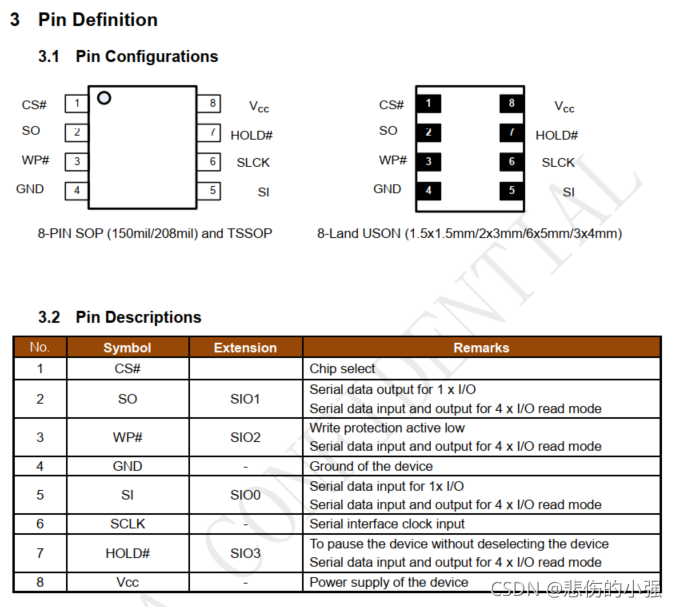
串行数据输入、输出和 IOs(DI、DO 和 IO0、IO1、IO2、IO3)
W25Q64、W25Q16 和 W25Q32 支持标准 SPI、双倍 SPI 和四倍 SPI。标准的 SPI 传输用单向的 DI(输入)引脚连续的写命令、地址或者数据在串行时钟(CLK)的上升沿时写入到芯片内。
写保护(/WP)
写保护引脚(/WP)用来保护状态寄存器。和状态寄存器的块保护位(SEC、TB、BP2、BP1 和BP0)和状态寄存器保护位(SRP)对存储器进行一部分或者全部的硬件保护。/WP 引脚低电平有效。当状态寄存器 2 的 QE 位被置位了,/WP 引脚(硬件写保护)的功能不可用。
保持端(/HOLD)
当/HOLD 引脚是有效时,允许芯片暂停工作。在/CS 为低电平时,当/HOLD 变为低电平,DO 引脚将变为高阻态,在 DI 和 CLK 引脚上的信号将无效。当/HOLD 变为高电平,芯片恢复工作。/HOLD 功能用在当有多个设备共享同一 SPI 总线时。/HOLD 引脚低电平有效。当状态寄存器 2 的 QE 位被置位了,/ HOLD 引脚的功能不可用。
串行时钟(CLK)
串行时钟输入引脚为串行输入和输出操作提供时序。(见 SPI 操作)。
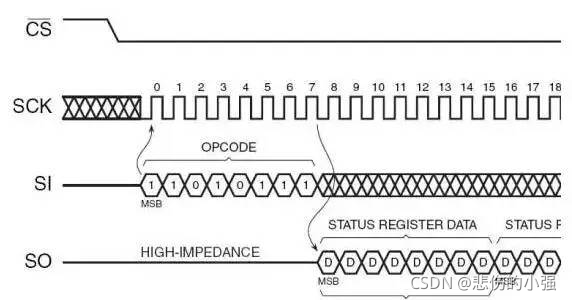
设备数据传输是从高位开始,数据传输的格式为 8bit,数据采样从第二个时间边沿开始,空闲状态时,时钟线 clk 为高电平。
W25Q64操作原理
通过SPI接口,用标准的SPI协议发送相应指令给flash,然后flash根据命令进行各种相关操作。
① 写使能:06H
② 读状态寄存器指令:05H
③ 写状态寄存器指令:01H
④ 读数据:03H
⑤ 页写:02H
⑥ 扇区擦除指令:20H
⑦ 块擦除指令:D8H
⑧ 芯片擦除指令:07H
⑨ 掉电指令:B9H
⑩ 读ID指令:90H


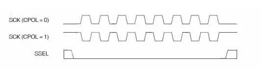
极性CPOL和相位CPHA
(1) CKPOL (Clock Polarity) = CPOL = POL = Polarity = (时钟)极性
(2) CKPHA (Clock Phase) = CPHA = PHA = Phase = (时钟)相位
CPOL和CPHA,分别都可以是0或时1,对应的四种组合就是:

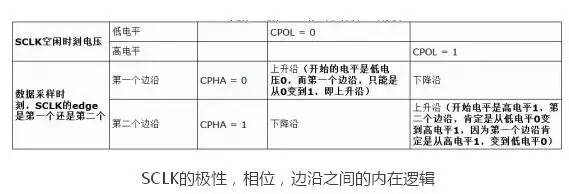
SPI的CPOL,表示当SCLK空闲idle的时候,其电平的值是低电平0还是高电平1:CPOL=0,时钟空闲idle时候的电平是低电平,所以当SCLK有效的时候,就是高电平,就是所谓的active-high。
CPOL=1,时钟空闲idle时候的电平是高电平,所以当SCLK有效的时候,就是低电平,就是所谓的active-low。
CPHA=0,表示第一个边沿:
对于CPOL=0,idle时候的是低电平,第一个边沿就是从低变到高,所以是上升沿;
对于CPOL=1,idle时候的是高电平,第一个边沿就是从高变到低,所以是下降沿;
CPHA=1,表示第二个边沿:
对于CPOL=0,idle时候的是低电平,第二个边沿就是从高变到低,所以是下降沿;
对于CPOL=1,idle时候的是高电平,第一个边沿就是从低变到高,所以是上升沿;
示例代码
DTSI
w25q64: w25q64@00 {

       status = "okay";
       compatible = "rockchip,w25q64";
       reg = <0x00>;
       spi-max-frequency = <24000000>;
       wp-gpio = <&gpio0 12 GPIO_ACTIVE_HIGH>; /*GPIO0_B4*/
//     spi-cs-high;
       spi-cpha;       /*SPI mode: CPHA = 1*/
       spi-cpol;       /*SPI mode: CPOL = 1*/
};
源码
w25q64.c
#include <linux/init.h>
#include <linux/module.h>
#include <linux/ioctl.h>
#include <linux/fs.h>
#include <linux/device.h>
#include <linux/err.h>
#include <linux/list.h>
#include <linux/errno.h>
#include <linux/mutex.h>
#include <linux/slab.h>
#include <linux/compat.h>
#include <linux/of.h>
#include <linux/of_device.h>
#include <linux/kernel.h>

#include <linux/spi/spi.h>
#include <linux/spi/spidev.h>

#include <linux/delay.h>
#include <linux/uaccess.h>
#include <linux/of_gpio.h>
#include "w25q64.h"

/*
 * This supports access to SPI devices using normal userspace I/O calls.
 * Note that while traditional UNIX/POSIX I/O semantics are half duplex,
 * and often mask message boundaries, full SPI support requires full duplex
 * transfers.  There are several kinds of internal message boundaries to
 * handle chipselect management and other protocol options.
 *
 * SPI has a character major number assigned.  We allocate minor numbers
 * dynamically using a bitmask.  You must use hotplug tools, such as udev
 * (or mdev with busybox) to create and destroy the /dev/spidevB.C device
 * nodes, since there is no fixed association of minor numbers with any
 * particular SPI bus or device.
 */
#define SPIDEV_MAJOR			155	/* assigned */
#define N_SPI_MINORS			32	/* ... up to 256 */

/*W25Q64 CMD*/
#define WRITE_ENABLE 0x06
#define PAGE_PROGRAM 0x02
#define READ_DATA 0x03
#define WRITE_STATUS_REG 0x01
#define READ_STATUS_REG 0x05
#define CHIP_ERASE 0xc7
#define SECTOR_ERASE 0x20
#define BLOCK_32KB_ERASE 0x52
#define BLOCK_64KB_ERASE 0xD8
#define READ_DEVICE_ID 0x90
#define READ_UID 0x9F

static DECLARE_BITMAP(minors, N_SPI_MINORS);


/* Bit masks for spi_device.mode management.  Note that incorrect
 * settings for some settings can cause *lots* of trouble for other
 * devices on a shared bus:
 *
 *  - CS_HIGH ... this device will be active when it shouldn't be
 *  - 3WIRE ... when active, it won't behave as it should
 *  - NO_CS ... there will be no explicit message boundaries; this
 *	is completely incompatible with the shared bus model
 *  - READY ... transfers may proceed when they shouldn't.
 *
 * REVISIT should changing those flags be privileged?
 */
#define SPI_MODE_MASK		(SPI_CPHA | SPI_CPOL | SPI_CS_HIGH \
				| SPI_LSB_FIRST | SPI_3WIRE | SPI_LOOP \
				| SPI_NO_CS | SPI_READY | SPI_TX_DUAL \
				| SPI_TX_QUAD | SPI_RX_DUAL | SPI_RX_QUAD)

struct spidev_data {

	dev_t			devt;
	spinlock_t		spi_lock;
	struct spi_device	*spi;
	struct list_head	device_entry;

	/* TX/RX buffers are NULL unless this device is open (users > 0) */
	struct mutex		buf_lock;
	unsigned		users;
	u8			*tx_buffer;
	u8			*rx_buffer;
	u32			speed_hz;
	unsigned int cur_addr;
	unsigned wp_gpio;
};

static LIST_HEAD(device_list);
static DEFINE_MUTEX(device_list_lock);

static unsigned bufsiz = 4096;
module_param(bufsiz, uint, S_IRUGO);
MODULE_PARM_DESC(bufsiz, "data bytes in biggest supported SPI message");

/*-------------------------------------------------------------------------*/

static char spi_w25x_status(struct spi_device *spi)
{

	int     status;
	char tbuf[]={
   READ_STATUS_REG};
	char rbuf[1] = {
   1};
	struct spi_transfer     t = {

		.tx_buf         = tbuf,
		.len            = ARRAY_SIZE(tbuf),
	};

	struct spi_transfer     r = {

		.rx_buf         = rbuf,
		.len            = ARRAY_SIZE(rbuf),
	};
	struct spi_message      m;

	spi_message_init(&m);
	spi_message_add_tail(&t, &m);
	spi_message_add_tail(&r, &m);
	status = spi_sync(spi, &m);

	return rbuf[0];
}
//modified by xzq degain for retry 5 times @20211105
static int spi_w25x_wait_ready(struct spi_device *spi )
{

	char retval = 1;
	int retry = 5;
	dev_dbg(&spi->dev, "wait ready...");
	do {

		retval = spi_w25x_status(spi);
		retval &= 0xff;
		retval &= 1;
		retry --;
		mdelay(5);
	}while((retval != 0) && (retry != 0));
	if(retval)
		dev_err(&spi->dev,"no ready\n");
	else
		dev_dbg(&spi->dev, "OK\n");
	return 0;
}
//modified by xzq end
static int spi_w25x_write_enable(struct spi_device *spi)
{

	int     status;
	char cmd_buf[1] = {
   WRITE_ENABLE};
	struct spi_transfer cmd = {

		.tx_buf = cmd_buf,
		.len = ARRAY_SIZE(cmd_buf),
	};

	struct spi_message      m;

	spi_message_init(&m);
	spi_message_add_tail(&cmd, &m);

	status = spi_sync(spi, &m);

	dev_dbg(&spi->dev, "write enable\n");

	return status;
}

static int spi_read_w25x_id_0(struct spi_device *spi)
{

	int     status;
	char tbuf[]={
   READ_UID};
	char rbuf[5];

	struct spi_transfer     t = {

		.tx_buf         = tbuf,
		.len            = ARRAY_SIZE(tbuf),
	};

	struct spi_transfer     r = {

		.rx_buf         = rbuf,
		.len            = ARRAY_SIZE(rbuf),
	};
	struct
最低0.47元/天 解锁文章


 7572
7572


 被折叠的 条评论
为什么被折叠?
被折叠的 条评论
为什么被折叠?
 到【灌水乐园】发言


