


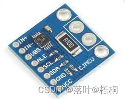
最近突然想自己做一个测量电压电流的电路,于是在网上买了一块INA226模块做电流电压功率检测设备
硬件图:

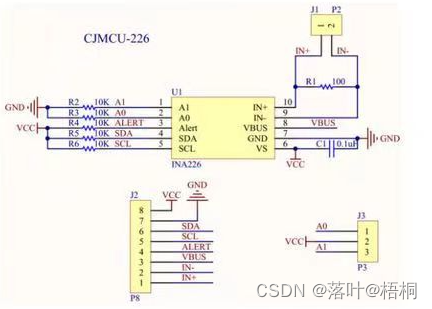
原理图:
硬件电路接线图:
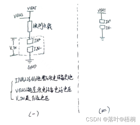
实测第一种接法可测量电流、电压、功率,但是有一定误差
第二种接法只测量电流
附上程序:
INA226.h
#ifndef __INA226_H__
#define __INA226_H__
#include "app_api.h"

#define READ_ADDR                  0x81	 //A0=GND,A1=GND // R_addr=1, W_addr=0
#define WRITE_ADDR                 0x80

#define Config_Reg                 0x00  //配置寄存器  读写
#define Shunt_V_Reg                0x01  //分流电压    读
#define Bus_V_Reg                  0x02  //总线电压    读
#define Power_Reg                  0x03  //电源功率    读
#define Current_Reg                0x04  //电流        读
#define Calib_Reg                  0x05  //校准,设定满量程范围以及电流和功率测数的
#define Mask_En_Reg                0x06  //屏蔽 使能 警报配置和转换准备就绪
#define Alert_Reg                  0x07  //包含与所选警报功能相比较的限定值
#define Man_ID_Reg                 0xFE  //0x5449
#define ID_Reg                     0xFF  //0x2260

uint16_t INA226_Read2Byte(uint8_t reg_addr);
uint8_t INA226_Write2Byte(uint8_t reg_addr,uint16_t reg_data);
void INA226_Init(void);
void INA226_TEXT(void);

float INA226_GetVoltage(void);//获取总线电压mV
float INA226_GetShunt_Current(void);//获取分流电流mA
float INA226_GetShuntVoltage(void);//分流电压mV
float INA226_Get_Power(void);//获取功率
#endif
INA226.c
#include "INA226.h"
#include "myiic.h"
//
//本程序只供学习使用,未经作者许可,不得用于其它任何用途
//宇文工作室编写
//电流检测驱动 代码
//宇文工作室@haitian
//修改日期:2023/9/9
//All rights reserved
//


 //读2个字节,reg_addr为读的寄存器地址
 uint16_t INA226_Read2Byte(uint8_t reg_addr)
{
	uint16_t reg_data=0;
	uint16_t temp=0;
	IIC_Start();
	IIC_Send_Byte(WRITE_ADDR);
	if(IIC_Wait_Ack())return 0;
	IIC_Send_Byte(reg_addr);
	if(IIC_Wait_Ack())return 0;
	IIC_Start();
	IIC_Send_Byte(READ_ADDR);
	if(IIC_Wait_Ack())return 0;
	reg_data= IIC_Read_Byte(1);
	reg_data=(reg_data<<8)&0xFF00;
	temp=IIC_Read_Byte(0);
	IIC_Stop();
	reg_data|=temp;
	return reg_data;
}

//写2个字节,reg_addr为写的寄存器地址,reg_data为写的数据
uint8_t INA226_Write2Byte(uint8_t reg_addr,uint16_t reg_data)
{
	uint8_t data_high=(uint8_t)((reg_data&0xFF00)>>8);
	uint8_t data_low=(uint8_t)reg_data&0x00FF;
	IIC_Start();
	IIC_Send_Byte(WRITE_ADDR);
	if(IIC_Wait_Ack())return 0;
	IIC_Send_Byte(reg_addr );
	if(IIC_Wait_Ack())return 0;
	IIC_Send_Byte(data_high);
	if(IIC_Wait_Ack())return 0;
	IIC_Send_Byte(data_low);
	if(IIC_Wait_Ack())return 0;
	IIC_Stop();
	delay_ms(2);
	return 1;
}

void INA226_Init(void)
{
  IIC_Init();
  delay_ms(5);
  //写配置寄存器
	INA226_Write2Byte(Config_Reg, 0x4527);//0100_010_100_100_111 //16次平均,1.1ms,1.1ms,连续测量分流电压和总线电压
  //写校准寄存器
	INA226_Write2Byte(Calib_Reg, 0x0A00);//LSB选择0.02mA,分压电阻选0.0001R Cal=0.00512/(0.02mA*0.0001R)=2560
}

void INA226_TEXT(void)
{
  DEBUG_ASP("\r\n\n");
  DEBUG_ASP("data=%-5d, Bus_V   =%f mV\r\n", INA226_Read2Byte(Bus_V_Reg),INA226_Read2Byte(Bus_V_Reg)*1.25*0.001);
  DEBUG_ASP("data=%-5d, Shunt_V =%f mV\r\n", INA226_Read2Byte(Shunt_V_Reg),INA226_Read2Byte(Shunt_V_Reg)*2.5*0.001);
  DEBUG_ASP("data=%-5d, Curent  =%f mA\r\n", INA226_Read2Byte(Current_Reg),INA226_Read2Byte(Current_Reg)*0.02);
  DEBUG_ASP("data=%-5d, Power   =%f mW\r\n", INA226_Read2Byte(Power_Reg),INA226_Read2Byte(Power_Reg)*0.02*25);
  DEBUG_ASP("\r\n\n");
}

//获取总线电压mV
float INA226_GetVoltage(void)
{
  float Bus_V;
  Bus_V=INA226_Read2Byte(Shunt_V_Reg)*1.25*0.001;//总线电压LSB固定1.25mV
  DEBUG_ASP("data=%-5d, Bus_V  =%f mV\r\n", INA226_Read2Byte(Current_Reg),Bus_V);
  return Bus_V;
}

//分流电压mV
float INA226_GetShuntVoltage(void)
{
  float Shunt_V;
  Shunt_V=INA226_Read2Byte(Shunt_V_Reg)*2.5*0.001;//分流电压LSB固定2.5uV
  DEBUG_ASP("data=%-5d, Shunt_V=%f mV\r\n", INA226_Read2Byte(Current_Reg),Shunt_V);
  return Shunt_V;
}

//获取分流电流mA
float INA226_GetShunt_Current(void)
{
   float Curent;
   Curent=INA226_Read2Byte(Current_Reg)*0.02; //分流电流LSB选择0.02mA
   DEBUG_ASP("data=%-5d, Curent =%f mA\r\n", INA226_Read2Byte(Current_Reg),Curent);
   return Curent;
}

//获取功率
float INA226_Get_Power(void)
{
  float Power;
  Power=INA226_Read2Byte(Power_Reg)*0.02*25;//功率LSB固定分流电流LSB的25倍
  DEBUG_ASP("data=%-5d, Power=%f mW\r\n", INA226_Read2Byte(Power_Reg),Power);
  return Power;
}


 9912
9912

 被折叠的 条评论
为什么被折叠?
被折叠的 条评论
为什么被折叠?
 到【灌水乐园】发言


