


目录
前言:本文基于南邮通达学院电子电路课程设计,据了解很多转专业、专转本的同学在面对这门课时无从下手,因此小编写下这篇文章,想能给予基础较差的同学们些帮助(本人能力有限,如有差错,请见谅!)
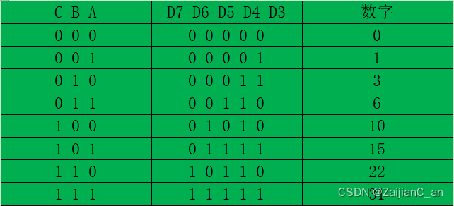
选路和二进制码转8421BCD码表(此表可用于分压的检测,0为低电平,1为高电平)

前言:
本文基于南邮通达学院电子电路课程设计,据了解很多转专业、专转本的同学在面对这门课时无从下手,因此小编写下这篇文章,想能给予基础较差的同学们些帮助!
Introduction:
This article is based on the electronic circuit course design of South Post Tongda College, and it is understood that many students who change majors and transfer this book are unable to start in the face of this course, so Xiaobian wrote this article, hoping to give students with poor foundation some help!
一、课程整体要求
数字式电缆对线器的主要功能有:
(1)可在远端预设芯线编号,近端测量出对应的芯线并且以数字显示出电缆芯线编号。
(2)可以检测到电缆芯线的短路或开路故障。可由人工单线接入测试,亦可自动测试。The main functions of the digital cable alignment device are:
(1) The core wire number can be preset at the remote end, and the corresponding core wire can be measured at the near end and the cable core wire number can be digitally displayed.
(2) The short circuit or open circuit fault of the cable core can be detected. It can be tested by manual single-line access or automatically.
由于此课程设计要求做完手动即可,且在实践过程中发现,虽然项目简单,但存在很多细节接线问题,所以本文在只做手动测试,即能达到学校(通达学院实践课程基本标准,若要求自动测试,请移步本站另一大佬的文章即可:https://blog.csdn.net/qq_36785019/article/details/102869539
本文图片思路来自此大佬并根据南邮通达实际情况作出筛选修改,通达学子可直接食用。)Because this course design requires manual completion, and found in the practice process, although the project is simple, but there are many details of the wiring problems, so this article only do manual testing, that is, can meet the basic standards of the school (Tongda College practice course, if you require automatic testing, please move to the site another big man's article can be
二、系统结构要求
远端编号器用于给被测电缆处于远端的芯线编号,电缆对线器在电缆近端测出各芯线与远端的对应关系并以数字显示出近端各芯线的编号数码。
Second, system structure requirements
The remote numbering device is used to number the core wires at the far end of the cable under test. The cable alignment device measures the corresponding relationship between the core wires at the near end of the cable and the remote end, and displays the numbering number of the core wires at the near end.

三、电气指标
(1)对线器一次可接入的芯线数量:8根
(2)芯线编号显示方式:1位数码显示,编号为1-8。
(3)显示及刷新时间:2s刷新一次,显示数码时间不少于1s。
(4)测试方式:远端编号并接好芯线后不再操作,近端用人工方式逐一选择被测芯线。
(5)电缆故障报警:当发现某条芯线有短路或开路故障时,发出告警信号——发光二极管亮。Three, electrical indicators
(1) The number of cores that can be accessed at a time: 8
(2) Core number display mode: 1-digit display, numbered 1-8.
(3) Display and refresh time: 2s refresh once, display digital time is not less than 1s.
(4) Test mode: After the remote end is numbered and connected, it is no longer operated, and the near end manually selects the tested core one by one.
(5) Cable fault alarm: When a certain core wire is found to have a short circuit or open circuit fault, an alarm signal is issued - the light-emitting diode is bright.
四、故障判断
①短路
用7427进行判断,用发光二极管显示。
②断路
用7430进行判断,用发光二极管显示。Fourth, fault judgment
① short circuit
Judge with 7427, display with LED.
② Open
Judge with 7430, display with LED.
具体接线流程(适用于手动测试):
准备阶段:很重要!!!!!!!!
(检查所发元器件是否正确,芯片型号是否与实验要求一致,特别检查八路开关是否能插紧)
1、拿到面包板,检测面包板是否坏损,学号是否一致正确
2、接好电源VCC、GND(接好后建议使用万用表测量是否均导通)
3、观察整体电路,做好电路元器件布局
Specific wiring process (for manual testing) :
Preparation: Very important !!!!!!!!
(Check whether the issued components are correct, whether the chip model is consistent with the experimental requirements, and especially check whether the eight-way switch can be plugged tightly)
1, get the bread board, check whether the bread board is damaged, whether the student number is consistent and correct
2. Connect the power supply VCC and GND (After connecting it, it is recommended to use a multimeter to measure whether it is all connected)
3. Observe the overall circuit and do a good job in the layout of circuit components
主体电路图:

按照主体电路图,先接好主体电路部分,最好按模块接线,接一段测一段,方便电路的检测。特别注意切勿带电操作,通电后,若发现芯片发热严重,请及时断电并检查线路是否连接错误、输出电压是否符合要求。
According to the main circuit diagram, first connect the main circuit part, it is best to connect according to the module connection, and test a section to facilitate the detection of the circuit. Pay special attention to do not live operation, after power, if you find that the chip heat is serious, please power off in time and check whether the line is connected incorrectly and the output voltage meets the requirements.
到此,只剩555电路和报警电路了,你通过接入信号发生器调试(500khz,0-5v),已经可以显示正确数值并通过八路开关可控制数码管显示对应数字了。
若你不能完成上述要求,请检查:
你的接线是否接对、电阻是否使用正确、引脚是否插到位。
555电路及报警电路见附录。
At this point, only 555 circuit and alarm circuit, you through the access signal generator debugging (500khz, 0-5v), has been able to display the correct value and through the eight-way switch can control the digital display of the corresponding number.
If you cannot complete the above requirements, please check:
Whether your wires are connected correctly, whether the resistance is used correctly, and whether the pins are inserted in place.
555 circuit and alarm circuit see appendix.
注意:555时钟电路用于代替信号发生器,接好后则不用使用信号发生器了。555上的输出OUT接到ADC0809的10号引脚clock处。
Note: The 555 clock circuit is used to replace the signal generator, and once connected, the signal generator is not used. The output OUT on 555 is connected to pin 10 clock of the ADC0809.
附件涵盖555电路图、报警电路图、整体电路图,先接好各个电路自身,再按照整体电路图将555电路和报警电路接入到主体电路图中,仔细检查各个端口连线,避免出现插错孔、剥线过段引起的接触不良、不导通的情况。确认线路无误后,通电即可。
The attachments include 555 circuit diagram, alarm circuit diagram, and overall circuit diagram. First connect each circuit itself, and then connect 555 circuit and alarm circuit to the main circuit diagram according to the overall circuit diagram. Carefully check the connection of each port to avoid poor contact and non-conduction caused by inserting wrong holes and stripping lines. After confirming that the line is correct, power on.
附件:
555电路
555 circuit

报警电路:7404脉冲发生电路&判决电路(短路、断路)
Alarm circuit: 7404 pulse generating circuit & Decision circuit (short circuit, open circuit)

选路和二进制码转8421BCD码表(此表可用于分压的检测,0为低电平,1为高电平)
Routing and binary code transfer 8421BCD code table (This table can be used for partial voltage detection, 0 is low, 1 is high)
实物完成图(手动测试)
Physical finished drawing (manual test)

整体电路图
Overall circuit diagram

八段数码管
Eight pieces of nixie tube


引脚图1:八路开关、ADC0809、28C64、4511
八路开关(8-channel switch)是一种电子开关设备,它具有8个独立的通道,可以用于控制电路中的开关操作。每个通道可以通过控制信号打开或关闭,从而控制相应的电路路径。
ADC0809是一款8位逐次逼近型模数转换器(Analog-to-Digital Converter,ADC),它可以将模拟信号转换为相应的数字表示。ADC0809具有8个输入通道,可以将模拟信号转换为8位的数字输出。它逐个通道地进行转换,并将转换结果以并行方式输出。
28C64是一款64K位的电子可擦除可编程只读存储器(Electrically Erasable Programmable Read-Only Memory,EEPROM)。它具有64K位(8K字节)的存储容量,可以用于存储数据。28C64可以通过编程和擦除操作来写入和擦除存储的数据,因此它是一种非易失性存储器。
4511是一款BCD(Binary Coded Decimal)至七段数码管译码器(Decoder)和驱动器(Driver)。它可以将4位BCD码转换为相应的七段数码管显示输出。4511具有4个输入线,用于接收BCD码输入,并具有7个输出线,用于控制七段数码管的显示。
Pin Figure 1: eight-way switch, ADC0809, 28C64, 4511
An 8-channel switch is an electronic switching device that has eight separate channels that can be used to control switching operations in a circuit. Each channel can be opened or closed by a control signal, thus controlling the corresponding circuit path.
The ADC0809 is an 8-bit sequential approximation analog-to-digital Converter (ADC) that converts an Analog signal to its corresponding Digital representation. The ADC0809 has eight input channels that convert an analog signal into an 8-bit digital output. It performs the conversion channel by channel and outputs the result of the conversion in parallel.
The 28C64 is an Electrically Erasable Programmable Read-Only Memory (EEPROM) with 64K bits. It has a storage capacity of 64K bits (8K bytes) and can be used to store data. The 28C64 can write and erase stored data by programming and erasing operations, so it is a non-volatile memory.
The 4511 is a BCD (Binary Coded Decimal) to seven-segment Decoder and Driver. It can convert the 4-bit BCD code into the corresponding 7-segment nixie display output. The 4511 has four input lines for receiving BCD code input and seven output lines for controlling the display of the seven-segment nixie tube.

引脚图2:7400、7404、7427、7430
1. 7400:7400是一款集成电路(IC),属于TTL(Transistor-Transistor Logic,晶体管-晶体管逻辑)系列。它是一个四输入二与门(Quad 2-Input NAND Gate),具有四个独立的二输入与门。每个门的输出是根据其两个输入的逻辑与运算结果确定的。
2. 7404:7404也是一款TTL系列的IC。它是一个六反相器(Hex Inverter),具有六个独立的反相器。每个反相器将输入信号取反并输出。
3. 7427:7427是一款TTL系列的IC,它是一个三输入三与门(Triple 3-Input AND Gate)。它具有三个独立的三输入与门,根据三个输入的逻辑与运算结果确定输出。
4. 7430:7430也是一款TTL系列的IC,它是一个八输入与非门(8-Input NAND Gate with Open Collector Outputs)。它具有八个独立的输入,并根据这些输入的逻辑与运算结果取反输出。此外,它的输出还具有开漏输出结构。
Pin Figure 2:7400, 7404, 7427, 7430
1. 7400: The 7400 is an integrated circuit (IC) belonging to the TTL (Transistor-Transistor Logic) family. It is a Quad 2-Input NAND Gate with four independent two-input and gates. The output of each gate is determined by the logical and operational results of its two inputs.
2. 7404:7404 is also a TTL series IC. It is a Hex Inverter with six separate inverters. Each inverter inverts the input signal and outputs it.
3. 7427:7427 is a TTL series IC, which is a Triple 3-input AND Gate. It has three independent three inputs and gates, and the output is determined according to the logic and operation results of the three inputs.
4. 7430:7430 is also a TTL series IC, which is an 8-Input NAND Gate with Open Collector Outputs. It has eight independent inputs and takes the inverse output according to the logic and results of these inputs. In addition, its output has an open-leak output structure.

希望能给予你一些帮助!加油!
Hope to give you some help! refuel!


 766
766


 被折叠的 条评论
为什么被折叠?
被折叠的 条评论
为什么被折叠?
 到【灌水乐园】发言


