


SDP定义
SDP定义
联网系统中SIP消息体中携带的SDP内容应符合IETFRFC2327的相关要求。应有如下字段:
Sessiondescription:
v= (protocolversion)
o= (owner/creatorandsessionidentifier)
s= (sessionname)
u=* (URIofdescription)
c=* (connectioninformation-notrequiredifincludedinallmedia)
Timedescription:
t= (timethesessionisactive)
Mediadescription
m= (medianameandtransportaddress)
c=* (connectioninformation-optionalifincludedatsession-level)
b=* (bandwidthinformation)
a=* (zeroormoremediaattributelines)
y=*(SSRC)
f=*(媒体描述)
说明:
a字段:启用IETFRFC4566中对a字段的定义a=rtpmap:<payloadtype><encodingname>/
<clockrate>[/<encodingparameters>] 中的<encodingname>,利用该属性携带编码器厂商名称(如:
企业1或企业2编码名称 DAHUA 或 HIKVISION)。该属性表明该流为某厂商编码器编码且是不符
合本标准规定的媒体流,符合本标准规定的媒体流无需该属性。
s字段:在向SIP服务器和媒体流接收者/媒体流发送者之间的SIP消息中,使用s字段标识请求媒
体流的操作类型。“Play”代表实时点播;“Playback”代表历史回放;“Download”代表文件下载;“Talk”
代表语音对讲。
u字段:u行应填写视音频文件的 URI。该 URI取值有两种方式:简捷方式和普通方式。简捷方式
直接采用产生该历史媒体的媒体源(如某个摄像头)的设备ID(应符合6.1.2的规定)以及相关参数,参
数用“:”分隔;普通方式采用http://存储设备ID[/文件夹]* /文件名,[/文件夹]*为0-N 级文件夹。
m 字段:m 字段描述媒体的媒体类型、端口、传输层协议、负载类型等内容。媒体类型采用“video”
标识传输视频或视音频混合内容,采用“audio”标识传输音频内容;传输方式采用“RTP/AVP”标识传输
层协议为 RTPoverUDP,采用“TCP/RTP/AVP”标识传输层协议为 RTPoverTCP。
  例如:
  “m=video6000RTP/AVP96”标识媒体类型为视频或视音频,传输端口为6000,采用 RTPover
   UDP传输方式,负载类型为96。
  “m=video6000TCP/RTP/AVP96”标识媒体类型为视频或视音频,传输端口为6000,采用 RTP
   overTCP传输方式,负载类型为96。
t字段:当回放或下载时,t行值为开始时间和结束时间,用“”分隔,时间格式见IETFRFC4566—
2006的5.9,采用 UNIX时间戳,即从1970年1月1日开始的相对时间。开始时间和结束时间均为要
回放或下载的音视频文件录制时间段中的某个时刻。
y字段:为十进制整数字符串,表示SSRC值。格式如下:dddddddddd。其中,第1位为历史或实时
媒体流的标识位,0为实时,1为历史;第2位至第6位取20位SIP监控域ID之中的4到8位作为域标
识,例如“13010000002000000001”中取数字“10000”;第7位至第10位作为域内媒体流标识,是一个与
当前域内产生的媒体流SSRC值后4位不重复的四位十进制整数。
f字段:f= v/编码格式/分辨率/帧率/码率类型/码率大小a/编码格式/码率大小/采样率
c字段:- 1.
- 2.
- 3.
- 4.
- 5.
- 6.
- 7.
- 8.
- 9.
- 10.
- 11.
- 12.
- 13.
- 14.
- 15.
- 16.
- 17.
- 18.
- 19.
- 20.
- 21.
- 22.
- 23.
- 24.
- 25.
- 26.
- 27.
- 28.
- 29.
- 30.
- 31.
- 32.
- 33.
- 34.
- 35.
- 36.
- 37.
- 38.
- 39.
- 40.
- 41.
- 42.
- 43.
- 44.
- 45.
SDP详情参考: https://www.rfc-editor.org/rfc/rfc2327
c字段的定义:
Connection Data

   c=<network type> <address type> <connection address>

   The "c=" field contains connection data.

   A session announcement must contain one "c=" field in each media
   description (see below) or a "c=" field at the session-level.  It may
   contain a session-level "c=" field and one additional "c=" field per
   media description, in which case the per-media values override the
   session-level settings for the relevant media.

   The first sub-field is the network type, which is a text string
   giving the type of network.  Initially "IN" is defined to have the
   meaning "Internet".

   The second sub-field is the address type.  This allows SDP to be used
   for sessions that are not IP based.  Currently only IP4 is defined.

   The third sub-field is the connection address.  Optional extra
   subfields may be added after the connection address depending on the
   value of the <address type> field.

   For IP4 addresses, the connection address is defined as follows:

   o Typically the connection address will be a class-D IP multicast

     group address.  If the session is not multicast, then the
     connection address contains the fully-qualified domain name or the
     unicast IP address of the expected data source or data relay or
     data sink as determined by additional attribute fields. It is not
     expected that fully-qualified domain names or unicast addresses

     will be given in a session description that is communicated by a
     multicast announcement, though this is not prohibited.  If a
     unicast data stream is to pass through a network address
     translator, the use of a fully-qualified domain name rather than an
     unicast IP address is RECOMMENDED.  In other cases, the use of an
     IP address to specify a particular interface on a multi-homed host
     might be required.  Thus this specification leaves the decision as
     to which to use up to the individual application, but all
     applications MUST be able to cope with receiving both formats.

   o Conferences using an IP multicast connection address must also have
     a time to live (TTL) value present in addition to the multicast
     address.  The TTL and the address together define the scope with
     which multicast packets sent in this conference will be sent. TTL
     values must be in the range 0-255.

     The TTL for the session is appended to the address using a slash as
     a separator.  An example is:

                           c=IN IP4 224.2.1.1/127

     Hierarchical or layered encoding schemes are data streams where the
     encoding from a single media source is split into a number of
     layers.  The receiver can choose the desired quality (and hence
     bandwidth) by only subscribing to a subset of these layers.  Such
     layered encodings are normally transmitted in multiple multicast
     groups to allow multicast pruning.  This technique keeps unwanted
     traffic from sites only requiring certain levels of the hierarchy.
     For applications requiring multiple multicast groups, we allow the
     following notation to be used for the connection address:

            <base multicast address>/<ttl>/<number of addresses>

     If the number of addresses is not given it is assumed to be one.
     Multicast addresses so assigned are contiguously allocated above
     the base address, so that, for example:

                          c=IN IP4 224.2.1.1/127/3

     would state that addresses 224.2.1.1, 224.2.1.2 and 224.2.1.3 are
     to be used at a ttl of 127.  This is semantically identical to
     including multiple "c=" lines in a media description:

                           c=IN IP4 224.2.1.1/127
                           c=IN IP4 224.2.1.2/127
                           c=IN IP4 224.2.1.3/127

     Multiple addresses or "c=" lines can only be specified on a per-
     media basis, and not for a session-level "c=" field.

     It is illegal for the slash notation described above to be used for
IP unicast addresses.- 1.
- 2.
- 3.
- 4.
- 5.
- 6.
- 7.
- 8.
- 9.
- 10.
- 11.
- 12.
- 13.
- 14.
- 15.
- 16.
- 17.
- 18.
- 19.
- 20.
- 21.
- 22.
- 23.
- 24.
- 25.
- 26.
- 27.
- 28.
- 29.
- 30.
- 31.
- 32.
- 33.
- 34.
- 35.
- 36.
- 37.
- 38.
- 39.
- 40.
- 41.
- 42.
- 43.
- 44.
- 45.
- 46.
- 47.
- 48.
- 49.
- 50.
- 51.
- 52.
- 53.
- 54.
- 55.
- 56.
- 57.
- 58.
- 59.
- 60.
- 61.
- 62.
- 63.
- 64.
- 65.
- 66.
- 67.
- 68.
- 69.
- 70.
- 71.
- 72.
- 73.
- 74.
- 75.
- 76.
- 77.
- 78.
- 79.
- 80.
- 81.
- 82.
- 83.
- 84.
- 85.
SSRC的使用
SSRC值由媒体流发送设备所在的SIP监控域产生,作为媒体流的标识使用。点播域内设备、点播外域设备 媒体流SSRC的处理方式分别说明如下:
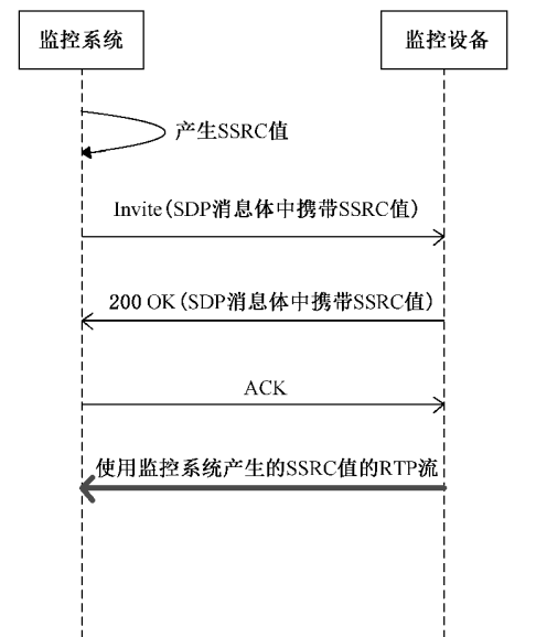
a) 点播域内设备媒体流SSRC处理方式
点播域内设备媒体流时,SSRC值由本域监控系统产生并通过Invite请求发送给设备使用,设备在回复的 200OK 消息中携带此值,设备在发送的媒体流中使用此值作为 RTP的SSRC值。
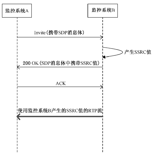
b) 点播外域设备媒体流SSRC处理方式
点播外域设备媒体流时,SSRC由被点播域产生并在被点播域回复的200OKSDP消息体中携带,被点播 域发送的 RTP码流使用该值作为SSRC值。


 3465
3465


 被折叠的 条评论
为什么被折叠?
被折叠的 条评论
为什么被折叠?
 到【灌水乐园】发言


