


1.帧资源
之前,我们在处理CPU和GPU的同步问题时,采取以下方法:在每帧绘制的结尾调用D3DApp::FlushCommandQueue函数,以确保GPU在每一帧都能正确完成所有命令的执行
这样做效率低下的原因:①每帧起始阶段,GPU不会执行任何命令,因为等待它处理的命令队列空空如也②每帧收尾阶段,CPU会等待GPU完成命令的处理 -- CPU和GPU在每一帧都存在各自的空闲时间
解决此问题的方案:以CPU每帧都需要更新的资源作为基本元素,创建一个环形数组,我们称这些资源为帧资源(frame resource),而这种循环数组通常是由3个帧资源元素 -- CPU往往会比GPU提前处理两帧,以确保GPU可持续工作
假设环形数组由元素0 1 2 组成
开始时CPU处理元素0 GPU等待CPU后处理元素0 因为CPU速度很快,所以GPU还在处理元素0时CPU可能已经处理完元素1 2了
当CPU处理完元素2 而GPU还在处理元素0时 CPU需要强制等待 因为GPU读资源时,该资源不能进行写操作,防止读到错误数据
这样一来CPU会提前为GPU多准备两帧的数据 减少GPU等待时间
// 存有CPU为构建每帧命令列表所需的资源
// 其中的数据将依程序而异,这取决于实际绘制所需的资源
struct FrameResource
{
public:

    FrameResource(ID3D12Device* device, UINT passCount, UINT objectCount);
    FrameResource(const FrameResource& rhs) = delete;
    FrameResource& operator=(const FrameResource& rhs) = delete;
    ~FrameResource();

    // 每一帧都需要自己的命令分配器 -- 因为在GPU处理完命令之前,不能重置命令分配器
    Microsoft::WRL::ComPtr<ID3D12CommandAllocator> CmdListAlloc;

    // 每一帧都需要自己的常量缓冲区(上传堆) -- GPU处理完之前,不能对其更新
    std::unique_ptr<UploadBuffer<PassConstants>> PassCB = nullptr;
    std::unique_ptr<UploadBuffer<ObjectConstants>> ObjectCB = nullptr;

    // 通过围栏值将命令标记到此围栏点,这使我们可以检测GPU是否还在使用这些资源
    UINT64 Fence = 0;
};

FrameResource::FrameResource(ID3D12Device* device, UINT passCount, UINT objectCount)
// PassCB的数量:passCount ObjectCB的数量:objectCount
{
    ThrowIfFailed(device->CreateCommandAllocator(
        D3D12_COMMAND_LIST_TYPE_DIRECT,
		IID_PPV_ARGS(CmdListAlloc.GetAddressOf())));

    PassCB = std::make_unique<UploadBuffer<PassConstants>>(device, passCount, true);
    ObjectCB = std::make_unique<UploadBuffer<ObjectConstants>>(device, objectCount, true);

}

FrameResource::~FrameResource()
{

}
实例化一个由3个帧资源所构成的向量,并留有特定的成员变量来记录当前的帧资源:
const int gNumFrameResources = 3;
std::vector<std::unique_ptr<FrameResource>> mFrameResources;
FrameResource* mCurrFrameResource = nullptr;
int mCurrFrameResourceIndex = 0;

void BoxApp::BuildFrameResources()
{
    for(int i = 0l i < gNumFrameResources; ++i)
    {
        mFrameResources.push_back(std::make_unique<FrameResource>(
            md3dDevice.Get(), 1, (UINT)mAllRitmes.size()
        ));
    }
}
现在CPU端处理第n帧的算法是:
void BoxApp::Update(const GameTimer& gt)
{
    mCurrFrameResourceIndex = (mCurrFrameResourceIndex + 1) % gNumFrameResouces;
    mCurrFrameResource = mFrameResources[mCurrFrameResourceIndex].get();

    // GPU端是否已经执行完当前帧资源的所有命令呢?
    if(mCurrFrameResource->Fence != 0 && mCommandQueue->GetLastCompletedFence() < mCurrFrameResource->Fence)
    {
        HANDLE eventHandle = CreateEventEx(nullptr, false, false, EVENT_ALL_ACCESS);
        ThrowIfFailed(mCommandQueue->SetEventOnFenceCompletion(
            mCurrFrameResource->Fence, eventHandle
        ));
        WaitForSingleObject(eventHandle, INFINITE);
        CloseHandle(eventHandle);
    }

    // 更新mCurrFrameResource内的资源
    // [...]
}

void BoxApp::Draw(const GameTimer& gt)
{
    // [...] 构建和提交本帧的命令列表

    // 增加围栏值,将命令标记到此围栏点 -- CPU端
    mCurrFrameResource->Fence = ++mCurrentFence;

    // GPU端 -- 通过一条命令
    mCommandQueue->Signal(mFence.Get(), mCurrentFence);
}
CPU处理帧的速度总是遥遥领先GPU
2.渲染项
我们把单次绘制调用过程中,需要向渲染流水线提交的数据集称为渲染项
struct RenderItem
{
    RenderItem() = default;

    XMFLOAT4X4 World = MathHelper::Identity4x4();

    // dirty flag(已更新标记)来表示物体的相关数据已发生改变,这意味着我们需要更新常量缓冲区
    // 每个FrameResource中都有常量缓冲区,所以我们必须对每个FrameResource都进行更新
    int NumFramesDirty = gNumFrameResources;
    // 问题:其中一个帧资源正在被GPU使用,怎么修改它的数据 -- 导致死锁?


    // 该索引指向的GPU常量缓冲区对应于当前渲染项中的物体常量缓冲区
    UINT ObjCBIndex = -1;

    // 渲染项参与绘制的几何体
    MeshGeometry* Geo = nullptr;

    // 图元拓扑
    D3D12_PRIMITIVE_TOPOLOGY PrimitiveType = D3D_PRIMITIVE_TOPOLOGY_TRIANGLELIST;

    // DrawIndexedInstanced参数
    UINT IndexCount = 0;
    UINT StartIndexLocation = 0;
    int BaseVertexLocation = 0;
};我们的应用程序将根据各渲染项的绘制目的,把它们保存在不同的向量里。即按照不同PSO所需的渲染项,将它们划分到不同的向量之中。
// 所有渲染项
std::vector<std::unique_ptr<RenderItem>> mAllRitems;

// 根据PSO来划分渲染项
std::vector<RenderItem*> mOpaqueRitems;
std::vector<RenderItem*> mTransparentRitems;
3.渲染过程中使用的常量数据
我们在自己实现的FrameResource类中引进了一个新的常量缓冲区:
std::unique_ptr<UploadBuffer<PassConstants>> PassCB = nullptr;该缓冲区中存储的数据内容(观察位置、观察矩阵与投影矩阵以及屏幕分辨率相关的信息)会根据特定的渲染过程而确定下来:
cbuffer cbPass : register(b1)
{
    float4x4 gView;
    float4x4 gInvView;
    float4x4 gProj;
    float4x4 gInvProj;
    float4x4 gViewProj;
    float4x4 gInvViewProj;
    float3 gEyePosW;
    float cbPerObjectPad1;
    float2 gRenderTargetSize;
    float2 gInvRenderTargetSize;
    float gNearZ;
    float gFarZ;
    float gTotalTime;
    float gDeltaTime;
};我们也修改了物体常量缓冲区(cbPerObject),使之仅存储一个与物体有关的常量
cbuffer cbPerObject : register(b0)
{
	float4x4 gWorld;
};
上述调整的思路:基于资源的更新频率对常量数据进行分组,在每次渲染过程中,只需将本次所用的常量更新一次;而每当某个物体的世界矩阵发生改变时,只需更新该物体的相关常量即可。我们在绘制每一帧画面时,这两个方法都会被Update函数调用一次:
void LandAndWavesApp::UpdateObjectCBs(const GameTimer& gt)
{
	auto currObjectCB = mCurrFrameResource->ObjectCB.get();
	for(auto& e : mAllRitems)
	{
		// 只要常量发生了改变就得更新常量缓冲区内的数据,对每个帧资源都进行更新
		if(e->NumFramesDirty > 0)
		{
			XMMATRIX world = XMLoadFloat4x4(&e->World);

			ObjectConstants objConstants;
			XMStoreFloat4x4(&objConstants.World, XMMatrixTranspose(world));

			currObjectCB->CopyData(e->ObjCBIndex, objConstants);

			// Next FrameResource need to be updated too.
			e->NumFramesDirty--;
		}
	}
}
// 一个帧资源中只有一个PassCB 但可能有多个cbPerObject⭐他这里NumFramesDirty这个数据,每个渲染项都有自己的NumFramesDirty,且初始化为帧资源个数,也就是他能保证该渲染项在所有帧资源中都得以改变
更新PassCB:
void LandAndWavesApp::UpdateMainPassCB(const GameTimer& gt)
{
	XMMATRIX view = XMLoadFloat4x4(&mView);
	XMMATRIX proj = XMLoadFloat4x4(&mProj);

	XMMATRIX viewProj = XMMatrixMultiply(view, proj);
	XMMATRIX invView = XMMatrixInverse(&XMMatrixDeterminant(view), view);
	XMMATRIX invProj = XMMatrixInverse(&XMMatrixDeterminant(proj), proj);
	XMMATRIX invViewProj = XMMatrixInverse(&XMMatrixDeterminant(viewProj), viewProj);

	XMStoreFloat4x4(&mMainPassCB.View, XMMatrixTranspose(view));
	XMStoreFloat4x4(&mMainPassCB.InvView, XMMatrixTranspose(invView));
	XMStoreFloat4x4(&mMainPassCB.Proj, XMMatrixTranspose(proj));
	XMStoreFloat4x4(&mMainPassCB.InvProj, XMMatrixTranspose(invProj));
	XMStoreFloat4x4(&mMainPassCB.ViewProj, XMMatrixTranspose(viewProj));
	XMStoreFloat4x4(&mMainPassCB.InvViewProj, XMMatrixTranspose(invViewProj));
	mMainPassCB.EyePosW = mEyePos;
	mMainPassCB.RenderTargetSize = XMFLOAT2((float)mClientWidth, (float)mClientHeight);
	mMainPassCB.InvRenderTargetSize = XMFLOAT2(1.0f / mClientWidth, 1.0f / mClientHeight);
	mMainPassCB.NearZ = 1.0f;
	mMainPassCB.FarZ = 1000.0f;
	mMainPassCB.TotalTime = gt.TotalTime();
	mMainPassCB.DeltaTime = gt.DeltaTime();

	auto currPassCB = mCurrFrameResource->PassCB.get();
	currPassCB->CopyData(0, mMainPassCB);
}注意:我们将world矩阵和view proj矩阵拆开,所以shader代码需要有所改变:
VertexOut VS(VertexIn vin)
{
    VertexOut vout;

    float4 posW = mul(float4(vin.PosL, 1.f), gWorld);
    vout.PosH = mul(posW, gViewProj);

    vout.Color = vin.Color;
    return vout;
} 现在,我们需要相应地调整根签名来使之获取所需的两个描述符表(需要两个描述符表,因为这两个CBV具有不同的更新频率 -- 渲染过程CBV仅需在每个渲染过程中设置一次;而物体CBV则需要针对每一个渲染项进行配置)
CD3DX12_DESCRIPTOR_RANGE cbvTable0;
cbvTable0.Init(D3D12_DESCRIPTOR_RANGE_TYPE_CBV, 1, 0);

CD3DX12_DESCRIPTOR_RANGE cbvTable1;
cbvTable0.Init(D3D12_DESCRIPTOR_RANGE_TYPE_CBV, 1, 1); // 描述符个数 register

CD3DX12_ROOT_PARAMETER slotRootParameter[2];

slotRootParameter[0].InitAsDescriptorTable(1, &cbvTable0);
slotRootParameter[1].InitAsDescriptorTable(1, &cbvTable1);

CD3DX12_ROOT_SIGNATURE_DESC rootSigDesc(2, slotRootParameter, 0, nullptr, D3D12_ROOT_SIGNATURE_FLAG_ALLOW_INPUT_ASSEMBLER_INPUT_LAYOUT);
不要在着色器中使用过多的常量缓冲区,出于性能的考虑,常量缓冲区的数量以少于5个为宜
4.不同形状的几何体
我们将程序性几何体的生成代码放入GeometryGenerator类中,其中有用于生成如栅格、球体、柱体以及长方体这类简单几何体的工具
MeshData是一个嵌套在GeometryGenerator类中用于存储顶点列表(vertices)和索引列表(indices)的简单结构体
class GeometryGenerator
{
public:

    using uint16 = std::uint16_t;
    using uint32 = std::uint32_t;

	struct Vertex
	{
		Vertex(){}
        Vertex(
            const DirectX::XMFLOAT3& p,
            const DirectX::XMFLOAT3& n,
            const DirectX::XMFLOAT3& t,
            const DirectX::XMFLOAT2& uv) :
            Position(p),
            Normal(n),
            TangentU(t),
            TexC(uv){}
		Vertex(
			float px, float py, float pz,
			float nx, float ny, float nz,
			float tx, float ty, float tz,
			float u, float v) :
            Position(px,py,pz),
            Normal(nx,ny,nz),
			TangentU(tx, ty, tz),
            TexC(u,v){}

        DirectX::XMFLOAT3 Position;
        DirectX::XMFLOAT3 Normal;
        DirectX::XMFLOAT3 TangentU;
        DirectX::XMFLOAT2 TexC;
	};

	struct MeshData
	{
		std::vector<Vertex> Vertices;
        std::vector<uint32> Indices32;

        std::vector<uint16>& GetIndices16()
        {
			if(mIndices16.empty())
			{
				mIndices16.resize(Indices32.size());
				for(size_t i = 0; i < Indices32.size(); ++i)
					mIndices16[i] = static_cast<uint16>(Indices32[i]);
			}

			return mIndices16;
        }

	private:
		std::vector<uint16> mIndices16;
	};

	// [...]
};①生成柱体网格:GeometryGenerator::CreateCylinder
定义一个柱体时,需要指定其顶、底面半径、高度、切片数量(截面分割的块数)以及堆叠层数
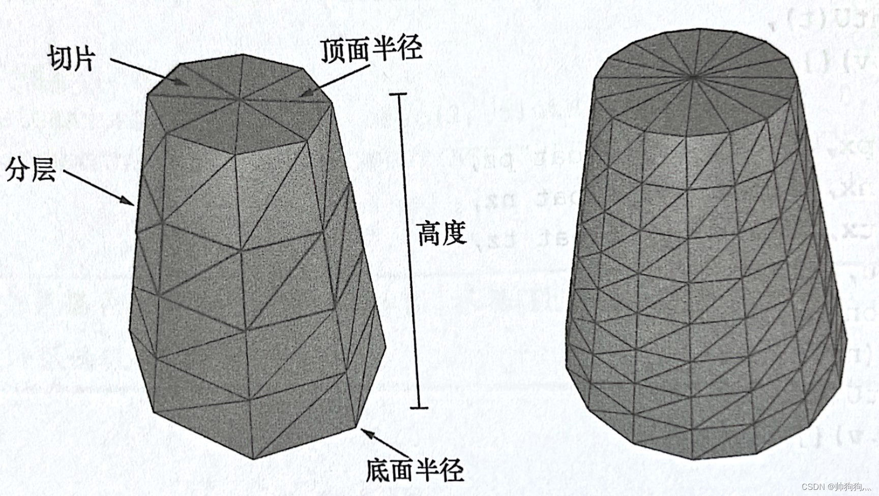
上图左侧圆台被分为8个切片,堆叠层数为4层;右侧圆台被分为16个切片,堆叠层数为8层
切片数:sliceCount 堆叠层数:stackCount 我们假设要生成的是中心在原点,且旋转轴平行于y轴的圆台,圆台的所有顶点都列于其各层侧面的"环"上,共有stackCount+1环。假设从底面上的环上开始用索引0表示,那么第i环的半径就是:,第i环的高度值为
生成圆台的基本思路就是遍历每个环,生成位于环上的各个顶点:
GeometryGenerator::MeshData
GeometryGenerator::CreateCylinder(float bottomRadius, float topRadius, float height, uint32 sliceCount, uint32 stackCount)
{
    MeshData meshData;


	// 构建堆叠层

    // Δh
	float stackHeight = height / stackCount;

	// Δr
	float radiusStep = (topRadius - bottomRadius) / stackCount;

	uint32 ringCount = stackCount+1;

	// 从底面开始,由下至上计算每个堆叠层环上的顶点坐标
	for(uint32 i = 0; i < ringCount; ++i)
	{
		float y = -0.5f*height + i*stackHeight; // h
		float r = bottomRadius + i*radiusStep; // r

		// 环上的各个顶点
		float dTheta = 2.0f*XM_PI/sliceCount;
		for(uint32 j = 0; j <= sliceCount; ++j)
		{
			Vertex vertex;

			float c = cosf(j*dTheta);
			float s = sinf(j*dTheta);

			vertex.Position = XMFLOAT3(r*c, y, r*s);

            // 纹理坐标 ??
            // 我们将圆台侧面展开,j越大,其对应纹理坐标x越大,除以sliceCount使x坐标保证在0~1范围内,i越大,纹理坐标y越小
            // 可以发现纹理坐标系uv以左上角为原点,u轴水平朝右,v轴竖直朝下
			vertex.TexC.x = (float)j/sliceCount;
			vertex.TexC.y = 1.0f - (float)i/stackCount;

			//   可以像下面那样参数化的方式来计算圆台顶点,我们引入与纹理坐标v方向相同的参数v,从而使副切线与纹理坐标v的方向相同
            //   r0为底面半径 r1为顶面半径
			//   y(v) = h - hv // 其中v位于[0,1].
			//   r(v) = r1 + (r0-r1)v
			//
			//   x(t, v) = r(v)*cos(t)
			//   y(t, v) = h - hv
			//   z(t, v) = r(v)*sin(t)
			//
			//  dx/dt = -r(v)*sin(t)
			//  dy/dt = 0
			//  dz/dt = +r(v)*cos(t)
			//
			//  dx/dv = (r0-r1)*cos(t)
			//  dy/dv = -h
			//  dz/dv = (r0-r1)*sin(t)

			// 正切线
			vertex.TangentU = XMFLOAT3(-s, 0.0f, c);

			float dr = bottomRadius-topRadius;
            // 副切线 bitangent--同时垂直于由法线与切线的向量
			XMFLOAT3 bitangent(dr*c, -height, dr*s);

			XMVECTOR T = XMLoadFloat3(&vertex.TangentU);
			XMVECTOR B = XMLoadFloat3(&bitangent);
			XMVECTOR N = XMVector3Normalize(XMVector3Cross(T, B));
			XMStoreFloat3(&vertex.Normal, N);

			meshData.Vertices.push_back(vertex);
		}
	}


	for(uint32 i = 0; i < stackCount; ++i)
	{
		for(uint32 j = 0; j < sliceCount; ++j)
		{
			meshData.Indices32.push_back(i*ringVertexCount + j);
			meshData.Indices32.push_back((i+1)*ringVertexCount + j);
			meshData.Indices32.push_back((i+1)*ringVertexCount + j+1);

			meshData.Indices32.push_back(i*ringVertexCount + j);
			meshData.Indices32.push_back((i+1)*ringVertexCount + j+1);
			meshData.Indices32.push_back(i*ringVertexCount + j+1);
		}
	}

    // 生成底面和顶面的端面,使之逼近于圆形,代码不难,就不在此处放出
	BuildCylinderTopCap(bottomRadius, topRadius, height, sliceCount, stackCount, meshData);
	BuildCylinderBottomCap(bottomRadius, topRadius, height, sliceCount, stackCount, meshData);

    return meshData;
}
每个环上的第一个顶点和最后一个顶点在位置上是重合的,但是二者的纹理坐标并不相同,只有这样做才能保证在圆台上绘制出正确的纹理
②生成球体网格:GeometryGenerator::CreateSphere
欲定义一个球体,要指定其半径,切片数量及其堆叠层数,其代码和圆台类似,不在此赘述。另外,想要获得椭圆,可以通过不等比缩放世界变换,将球体转换成椭圆体
③生成几何球体网格:GeometryGenerator::CreateGeosphere
在②中生成的球体网格,其中的三角形大小是不同的,这并不是我们所期望的。相对而言,几何球体利用面积相同且边长相同的三角形来逼近球体。
为了生成几何球体,我们以正二十面体为基础,细分其上的三角形,再根据给定的半径向球面投影新生成的顶点,反复重复这个过程,可以提高几何球体的曲面细分程度。
5.同时绘制多个几何体
GeometryGenerator 和 MeshData :
GeometryGenerator geoGen;
GeometryGenerator::MeshData box = geoGen.CreateBox(1.5f, 0.5f, 1.5f, 3);
GeometryGenerator::MeshData grid = geoGen.CreateGrid(20.f, 30.f, 60, 40);
GeometryGenerator::MeshData sphere = geoGen.CreateSphere(0.5f, 20, 20);
GeometryGenerator::MeshData cylinder = geoGen.CreateCylinder(0.5f, 0.3f, 3.0f, 20, 20);

// 按缓冲区排列顺序计算出各个几何体的submeshGeometry数据
UINT boxVertexOffset = 0;
UINT gridVertexOffset = (UINT)box.Vertices.size();
UINT sphereVertexOffset = gridVertexOffset + (UINT)grid.Vertices.size();
UINT cylinderVertexOffset = sphereVertexOffset + (UINT)sphere.Vertices.size();

UINT boxIndexOffset = 0;
UINT gridIndexOffset = (UINT)box.Indices32.size();
UINT sphereIndexOffset = gridIndexOffset + (UINT)grid.Indices32.size();
UINT cylinderIndexOffset = sphereIndexOffset + (UINT)sphere.Indices32.size();

// 构造子几何体的submeshGeometry:
SubmeshGeometry boxSubmesh;
boxSubmesh.IndexCount = (UINT)box.Indices32.size();
boxSubmesh.StartIndexLocation = boxIndexOffset;
boxSubmesh.BaseVertexLocation = boxVertexOffset;

SubmeshGeometry gridSubmesh;
gridSubmesh.IndexCount = (UINT)grid.Indices32.size();
gridSubmesh.StartIndexLocation = gridIndexOffset;
gridSubmesh.BaseVertexLocation = gridVertexOffset;

SubmeshGeometry sphereSubmesh;
sphereSubmesh.IndexCount = (UINT)sphere.Indices32.size();
sphereSubmesh.StartIndexLocation = sphereIndexOffset;
sphereSubmesh.BaseVertexLocation = sphereVertexOffset;

SubmeshGeometry cylinderSubmesh;
cylinderSubmesh.IndexCount = (UINT)cylinder.Indices32.size();
cylinderSubmesh.StartIndexLocation = cylinderIndexOffset;
cylinderSubmesh.BaseVertexLocation = cylinderVertexOffset;


// 合并顶点缓冲区和索引缓冲区 -- 顺序保持一致 -- 合并操作可以通过for循环遍历,或者insert
auto totalVertexCount =
	box.Vertices.size() +
	grid.Vertices.size() +
	sphere.Vertices.size() +
	cylinder.Vertices.size();

std::vector<Vertex> vertices(totalVertexCount);

UINT k = 0;
for(size_t i = 0; i < box.Vertices.size(); ++i, ++k)
{
	vertices[k].Pos = box.Vertices[i].Position;
    vertices[k].Color = XMFLOAT4(DirectX::Colors::DarkGreen);
}

for(size_t i = 0; i < grid.Vertices.size(); ++i, ++k)
{
	vertices[k].Pos = grid.Vertices[i].Position;
    vertices[k].Color = XMFLOAT4(DirectX::Colors::ForestGreen);
}

for(size_t i = 0; i < sphere.Vertices.size(); ++i, ++k)
{
	vertices[k].Pos = sphere.Vertices[i].Position;
    vertices[k].Color = XMFLOAT4(DirectX::Colors::Crimson);
}

for(size_t i = 0; i < cylinder.Vertices.size(); ++i, ++k)
{
	vertices[k].Pos = cylinder.Vertices[i].Position;
	vertices[k].Color = XMFLOAT4(DirectX::Colors::SteelBlue);
}

std::vector<std::uint16_t> indices;
indices.insert(indices.end(), std::begin(box.GetIndices16()), std::end(box.GetIndices16()));
indices.insert(indices.end(), std::begin(grid.GetIndices16()), std::end(grid.GetIndices16()));
indices.insert(indices.end(), std::begin(sphere.GetIndices16()), std::end(sphere.GetIndices16()));
indices.insert(indices.end(), std::begin(cylinder.GetIndices16()), std::end(cylinder.GetIndices16()));
indices.insert(indices.end(), std::begin(cylinder.GetIndices16()), std::end(cylinder.GetIndices16()));

// 将数据分别填入MeshGeometry CPU GPU端
auto geo = std::make_unique<MeshGeometry>();
geo->Name = "shapeGeo";

ThrowIfFailed(D3DCreateBlob(vbByteSize, &geo->VertexBufferCPU));
CopyMemory(geo->VertexBufferCPU->GetBufferPointer(), vertices.data(), vbByteSize);

ThrowIfFailed(D3DCreateBlob(ibByteSize, &geo->IndexBufferCPU));
CopyMemory(geo->IndexBufferCPU->GetBufferPointer(), indices.data(), ibByteSize);

geo->VertexBufferGPU = d3dUtil::CreateDefaultBuffer(md3dDevice.Get(),
	mCommandList.Get(), vertices.data(), vbByteSize, geo->VertexBufferUploader);

geo->IndexBufferGPU = d3dUtil::CreateDefaultBuffer(md3dDevice.Get(),
	mCommandList.Get(), indices.data(), ibByteSize, geo->IndexBufferUploader);

// MeshGeometry其他数据:
geo->VertexByteStride = sizeof(Vertex);
geo->VertexBufferByteSize = vbByteSize;
geo->IndexFormat = DXGI_FORMAT_R16_UINT;
geo->IndexBufferByteSize = ibByteSize;

geo->DrawArgs["box"] = boxSubmesh;
geo->DrawArgs["grid"] = gridSubmesh;
geo->DrawArgs["sphere"] = sphereSubmesh;
geo->DrawArgs["cylinder"] = cylinderSubmesh;

mGeometries[geo->Name] = std::move(geo);
上述最后一行代码,是我们在本书后面用到的一种通用模式:为每个几何体、PSO、纹理和着色器等创建新的变量名是一件很烦人的事,我们使用unordered_map,并根据名称在常数时间内寻找和引用所需的对象
std::unordered_map<std::string, std::unique_ptr<MeshGeometry>> mGeometries;
std::unordered_map<std::string, ComPtr<ID3DBlob>> mShaders;
std::unordered_map<std::string, ComPtr<ID3D12PipelineState>> mPSOs;
渲染项:
void ShapesApp::BuildRenderItems()
{
    // 创建多个renderItem
	auto boxRitem = std::make_unique<RenderItem>();
	XMStoreFloat4x4(&boxRitem->World, XMMatrixScaling(2.0f, 2.0f, 2.0f)*XMMatrixTranslation(0.0f, 0.5f, 0.0f));
	boxRitem->ObjCBIndex = 0;
	boxRitem->Geo = mGeometries["shapeGeo"].get();
	boxRitem->PrimitiveType = D3D_PRIMITIVE_TOPOLOGY_TRIANGLELIST;
	boxRitem->IndexCount = boxRitem->Geo->DrawArgs["box"].IndexCount;
	boxRitem->StartIndexLocation = boxRitem->Geo->DrawArgs["box"].StartIndexLocation;
	boxRitem->BaseVertexLocation = boxRitem->Geo->DrawArgs["box"].BaseVertexLocation;
	mAllRitems.push_back(std::move(boxRitem));

    auto gridRitem = std::make_unique<RenderItem>();
    gridRitem->World = MathHelper::Identity4x4();
	gridRitem->ObjCBIndex = 1;
	gridRitem->Geo = mGeometries["shapeGeo"].get();
	gridRitem->PrimitiveType = D3D_PRIMITIVE_TOPOLOGY_TRIANGLELIST;
    gridRitem->IndexCount = gridRitem->Geo->DrawArgs["grid"].IndexCount;
    gridRitem->StartIndexLocation = gridRitem->Geo->DrawArgs["grid"].StartIndexLocation;
    gridRitem->BaseVertexLocation = gridRitem->Geo->DrawArgs["grid"].BaseVertexLocation;
	mAllRitems.push_back(std::move(gridRitem));

	UINT objCBIndex = 2;
	for(int i = 0; i < 5; ++i)
	{
		auto leftCylRitem = std::make_unique<RenderItem>();
		auto rightCylRitem = std::make_unique<RenderItem>();
		auto leftSphereRitem = std::make_unique<RenderItem>();
		auto rightSphereRitem = std::make_unique<RenderItem>();

		XMMATRIX leftCylWorld = XMMatrixTranslation(-5.0f, 1.5f, -10.0f + i*5.0f);
		XMMATRIX rightCylWorld = XMMatrixTranslation(+5.0f, 1.5f, -10.0f + i*5.0f);

		XMMATRIX leftSphereWorld = XMMatrixTranslation(-5.0f, 3.5f, -10.0f + i*5.0f);
		XMMATRIX rightSphereWorld = XMMatrixTranslation(+5.0f, 3.5f, -10.0f + i*5.0f);

		XMStoreFloat4x4(&leftCylRitem->World, rightCylWorld);
		leftCylRitem->ObjCBIndex = objCBIndex++;
		leftCylRitem->Geo = mGeometries["shapeGeo"].get();
		leftCylRitem->PrimitiveType = D3D_PRIMITIVE_TOPOLOGY_TRIANGLELIST;
		leftCylRitem->IndexCount = leftCylRitem->Geo->DrawArgs["cylinder"].IndexCount;
		leftCylRitem->StartIndexLocation = leftCylRitem->Geo->DrawArgs["cylinder"].StartIndexLocation;
		leftCylRitem->BaseVertexLocation = leftCylRitem->Geo->DrawArgs["cylinder"].BaseVertexLocation;

		XMStoreFloat4x4(&rightCylRitem->World, leftCylWorld);
		rightCylRitem->ObjCBIndex = objCBIndex++;
		rightCylRitem->Geo = mGeometries["shapeGeo"].get();
		rightCylRitem->PrimitiveType = D3D_PRIMITIVE_TOPOLOGY_TRIANGLELIST;
		rightCylRitem->IndexCount = rightCylRitem->Geo->DrawArgs["cylinder"].IndexCount;
		rightCylRitem->StartIndexLocation = rightCylRitem->Geo->DrawArgs["cylinder"].StartIndexLocation;
		rightCylRitem->BaseVertexLocation = rightCylRitem->Geo->DrawArgs["cylinder"].BaseVertexLocation;

		XMStoreFloat4x4(&leftSphereRitem->World, leftSphereWorld);
		leftSphereRitem->ObjCBIndex = objCBIndex++;
		leftSphereRitem->Geo = mGeometries["shapeGeo"].get();
		leftSphereRitem->PrimitiveType = D3D_PRIMITIVE_TOPOLOGY_TRIANGLELIST;
		leftSphereRitem->IndexCount = leftSphereRitem->Geo->DrawArgs["sphere"].IndexCount;
		leftSphereRitem->StartIndexLocation = leftSphereRitem->Geo->DrawArgs["sphere"].StartIndexLocation;
		leftSphereRitem->BaseVertexLocation = leftSphereRitem->Geo->DrawArgs["sphere"].BaseVertexLocation;

		XMStoreFloat4x4(&rightSphereRitem->World, rightSphereWorld);
		rightSphereRitem->ObjCBIndex = objCBIndex++;
		rightSphereRitem->Geo = mGeometries["shapeGeo"].get();
		rightSphereRitem->PrimitiveType = D3D_PRIMITIVE_TOPOLOGY_TRIANGLELIST;
		rightSphereRitem->IndexCount = rightSphereRitem->Geo->DrawArgs["sphere"].IndexCount;
		rightSphereRitem->StartIndexLocation = rightSphereRitem->Geo->DrawArgs["sphere"].StartIndexLocation;
		rightSphereRitem->BaseVertexLocation = rightSphereRitem->Geo->DrawArgs["sphere"].BaseVertexLocation;

		mAllRitems.push_back(std::move(leftCylRitem));
		mAllRitems.push_back(std::move(rightCylRitem));
		mAllRitems.push_back(std::move(leftSphereRitem));
		mAllRitems.push_back(std::move(rightSphereRitem));
	}

	// All the render items are opaque.
	for(auto& e : mAllRitems)
		mOpaqueRitems.push_back(e.get());
}
RenderItem类的成员 ObjCBIndex:该索引指向的GPU常量缓冲区对应于当前渲染项中的物体常量缓冲区 -- 在每一个帧资源(FrameResource)中,有一个物体常量缓冲区ObjectCB数组[但我们往往叫这个常量缓冲区数组为“常量缓冲区”](当然还有一个渲染过程常量缓冲区,但其只有一个而不是数组所以不需要索引),这个Index就是当前物体(渲染项)在数组中的下标索引
假设有3个帧资源和n个渲染项,那么就有3n个物体常量缓冲区(object constant buffer:ObjectCB),和3个渲染流程常量缓冲区(pass constant buffer:PassCB)
-- 所以我们需要创建3(n+1)个常量缓冲区视图(CBV)
因此,我们还需要修改CBV堆以容纳额外的描述符:
void ShapesApp::BuildDescriptorHeaps()
{
    UINT objCount = (UINT)mOpaqueRitems.size();

    // 我们需要为每个帧资源中的每一个物体都创建一个CBV描述符
    // 为了容纳每个帧资源的渲染过程CBV而+1
    UINT numDescriptors = (objCount+1) * gNumFrameResources; // 3(n+1)

    // 保存渲染过程CBV的起始偏移量,在本程序中,这是排在最后面的3个描述符
    mPassCbvOffset = objCount * gNumFrameResources; // 描述符排列顺序: 3n 3

    D3D12_DESCRIPTOR_HEAP_DESC cbvHeapDesc;
    cbvHeapDesc.NumDescriptors = numDescriptors;
    cbvHeapDesc.Type = D3D12_DESCRIPTOR_HEAP_TYPE_CBV_SRV_UAV;
    cbvHeapDesc.Flags = D3D12_DESCRIPTOR_HEAP_FLAG_SHADER_VISIBLE;
    cbvHeapDesc.NodeMask = 0;
    ThrowIfFailed(md3dDevice->CreateDescriptorHeap(&cbvHeapDesc,
        IID_PPV_ARGS(&mCbvHeap)));
}
CBV扩建了,现在可以利用下列代码来填充CBV堆:
void ShapesApp::BuildConstantBufferViews()
{
    UINT objCBByteSize = d3dUtil::CalcConstantBufferByteSize(sizeof(ObjectConstants));

    UINT objCount = (UINT)mOpaqueRitems.size();

    // 处理ObjectCB:
    // 为3n个物体创建CBV和开辟常量缓冲区
    for(int frameIndex = 0; frameIndex < gNumFrameResources; ++frameIndex)
    {
        auto objectCB = mFrameResources[frameIndex]->ObjectCB->Resource(); // ObjectCB上传堆数组,存放一个个常量缓冲区的地方
        for(UINT i = 0; i < objCount; ++i)
        {
            D3D12_GPU_VIRTUAL_ADDRESS cbAddress = objectCB->GetGPUVirtualAddress();

            // 偏移到第i个位置
            cbAddress += i*objCBByteSize;

            // 偏移到该物体在描述符堆中的CBV
            int heapIndex = frameIndex*objCount + i; // CBV堆中对应位置的下标(该物体CBV的位置)
            auto handle = CD3DX12_CPU_DESCRIPTOR_HANDLE(mCbvHeap->GetCPUDescriptorHandleForHeapStart());
            handle.Offset(heapIndex, mCbvSrvUavDescriptorSize); // 偏移

            // 创建CBV
            D3D12_CONSTANT_BUFFER_VIEW_DESC cbvDesc;
            cbvDesc.BufferLocation = cbAddress; // CBV结构成员指定了常量缓冲区的位置
            cbvDesc.SizeInBytes = objCBByteSize;

            md3dDevice->CreateConstantBufferView(&cbvDesc, handle);
        }
    }

    // 处理PassCB:
    UINT passCBByteSize = d3dUtil::CalcConstantBufferByteSize(sizeof(PassConstants));

    for(int frameIndex = 0; frameIndex < gNumFrameResources; ++frameIndex)
    {
        auto passCB = mFrameResources[frameIndex]->PassCB->Resource();
        D3D12_GPU_VIRTUAL_ADDRESS cbAddress = passCB->GetGPUVirtualAddress();

        int heapIndex = mPassCbvOffset + frameIndex;
        auto handle = CD3DX12_CPU_DESCRIPTOR_HANDLE(mCbvHeap->GetCPUDescriptorHandleForHeapStart());
        handle.Offset(heapIndex, mCbvSrvUavDescriptorSize);

        D3D12_CONSTANT_BUFFER_VIEW_DESC cbvDesc;
        cbvDesc.BufferLocation = cbAddress;
        cbvDesc.SizeInBytes = passCBByteSize;

        md3dDevice->CreateConstantBufferView(&cbvDesc, handle);
    }
}
如何确定描述符的位置:①通过ID3D12DescriptorHeap::GetCPUDescriptorHandleForHeapStart方法,我们可以获取堆中第一个描述符的句柄②通过CD3DX12_CPU_DESCRIPTOR_HANDLE::Offset偏移到第i个该堆的描述符,偏移时需要知道该描述符堆中描述符的大小:
// RTV
mRtvDescriptorSize = md3dDevice->GetDescriptorHandleIncrementSize(
    D3D12_DESCRIPTOR_HEAP_TYPE_RTV
);

// DSV
mDsvDescriptorSize = md3dDevice->GetDescriptorHandleIncrementSize(
    D3D12_DESCRIPTOR_HEAP_TYPE_DSV
);

// CBV SRV UAV
mCbvSrvUavDescriptorSize = md3dDevice->GetDescriptorHandleIncrementSize(
    D3D12_DESCRIPTOR_HEAP_TYPE_CBV_SRV_UAV
);
CD3DX12_CPU_DESCRIPTOR_HANDLE handle = mCbvHeap->GetGPUDescriptorHandleForHeapStart();
// Offset两种用法2选1
handle.Offset(n * mCbvSrvDescriptorSize);
handle.Offset(n, mCbvSrvDescriptorSize);
最后一步,绘制场景,值得注意的是如何为了绘制物体而根据偏移量找到它在堆中所对应的CBV:
// DrawRenderItem函数是在Draw()内调用的
void ShapesApp::DrawRenderItems(ID3D12GraphicsCommandList* cmdList, const std::vector<RenderItem*>& ritems)
{
    UINT objCBByteSize = d3dUtil::CalcConstantBufferByteSize(sizeof(ObjectConstants));

	auto objectCB = mCurrFrameResource->ObjectCB->Resource();

    for(size_t i = 0; i < ritems.size(); ++i)
    {
        auto ri = ritems[i];

        cmdList->IASetVertexBuffers(0, 1, &ri->Geo->VertexBufferView());
        cmdList->IASetIndexBuffer(&ri->Geo->IndexBufferView());
        cmdList->IASetPrimitiveTopology(ri->PrimitiveType);

        // 在CBV堆中找到对应ObjCB的CBV的索引
        UINT cbvIndex = mCurrFrameResourceIndex*(UINT)mOpaqueRitems.size() + ri->ObjCBIndex;
        auto cbvHandle = CD3DX12_GPU_DESCRIPTOR_HANDLE(mCbvHeap->GetGPUDescriptorHandleForHeapStart());
        cbvHandle.Offset(cbvIndex, mCbvSrvUavDescriptorSize);

        // b0 -- ObjCB
        cmdList->SetGraphicsRootDescriptorTable(0, cbvHandle);

        cmdList->DrawIndexedInstanced(ri->IndexCount, 1, ri->StartIndexLocation, ri->BaseVertexLocation, 0);
    }
}
Draw函数:
void ShapesApp::Draw(const GameTimer& gt)
{
    auto cmdListAlloc = mCurrFrameResource->CmdListAlloc;

    ThrowIfFailed(cmdListAlloc->Reset());

    if(mIsWireframe)
    {
        ThrowIfFailed(mCommandList->Reset(cmdListAlloc.Get(), mPSOs["opaque_wireframe"].Get()));
    }
    else
    {
        ThrowIfFailed(mCommandList->Reset(cmdListAlloc.Get(), mPSOs["opaque"].Get()));
    }

    mCommandList->RSSetViewports(1, &mScreenViewport);
    mCommandList->RSSetScissorRects(1, &mScissorRect);

	mCommandList->ResourceBarrier(1, &CD3DX12_RESOURCE_BARRIER::Transition(CurrentBackBuffer(),
		D3D12_RESOURCE_STATE_PRESENT, D3D12_RESOURCE_STATE_RENDER_TARGET));

    // RTV DSV
    mCommandList->ClearRenderTargetView(CurrentBackBufferView(), Colors::LightSteelBlue, 0, nullptr);
    mCommandList->ClearDepthStencilView(DepthStencilView(), D3D12_CLEAR_FLAG_DEPTH | D3D12_CLEAR_FLAG_STENCIL, 1.0f, 0, 0, nullptr);
    mCommandList->OMSetRenderTargets(1, &CurrentBackBufferView(), true, &DepthStencilView());


    // Heap RootSignature
    ID3D12DescriptorHeap* descriptorHeaps[] = { mCbvHeap.Get() };
    mCommandList->SetDescriptorHeaps(_countof(descriptorHeaps), descriptorHeaps);

	mCommandList->SetGraphicsRootSignature(mRootSignature.Get());


    // b1 -- PassCB
    int passCbvIndex = mPassCbvOffset + mCurrFrameResourceIndex;
    auto passCbvHandle = CD3DX12_GPU_DESCRIPTOR_HANDLE(mCbvHeap->GetGPUDescriptorHandleForHeapStart());
    passCbvHandle.Offset(passCbvIndex, mCbvSrvUavDescriptorSize);
    mCommandList->SetGraphicsRootDescriptorTable(1, passCbvHandle);

    DrawRenderItems(mCommandList.Get(), mOpaqueRitems);


	mCommandList->ResourceBarrier(1, &CD3DX12_RESOURCE_BARRIER::Transition(CurrentBackBuffer(),
		D3D12_RESOURCE_STATE_RENDER_TARGET, D3D12_RESOURCE_STATE_PRESENT));


    ThrowIfFailed(mCommandList->Close());
    ID3D12CommandList* cmdsLists[] = { mCommandList.Get() };
    mCommandQueue->ExecuteCommandLists(_countof(cmdsLists), cmdsLists);


    ThrowIfFailed(mSwapChain->Present(0, 0));
	mCurrBackBuffer = (mCurrBackBuffer + 1) % SwapChainBufferCount;
    mCurrFrameResource->Fence = ++mCurrentFence;
    mCommandQueue->Signal(mFence.Get(), mCurrentFence);
}
6.细探根签名
根签名是由一系列根参数定义而成,之前我们创建过存有一个描述符表的根参数
根参数:
-
描述符表:描述符表引用的是描述符堆中的一块连续范围,用于确定要绑定的资源
-
根描述符:通过直接设置根描述符即可指示要绑定的资源,而无需将它存于描述符堆中 -- 但是只有常量缓冲区的CBV,缓冲区的SRV/UAV才可以以根描述符来实现资源绑定 注意,这意味着纹理的SRV并不能作为根描述符来实现资源绑定
-
根常量:借助根常量可直接绑定一系列32位的常量值
......该部分省略,在另一篇博客中有详细笔记......
// 描述符表:
mCommandList->SetGraphicsRootDescriptorTable(0, cbvHandle); // 堆中句柄

// 根描述符(CBV):
mCommandList->SetGraphicsRootConstantBufferView(0, objCBAddress); // 虚拟地址(无堆)

// 根常量:
mCommandList->SetGraphicsRoot32BitConstants(0, (UINT)weights.size(), weights.data(), 1); // 虚拟地址(无堆)
根参数中的排列顺序:根据变更频率高->低的顺序进行排列 -- 比如:高↘低:纹理 - cbPerObject - cbPass - cbMaterial
一般纹理(SRV)使用堆
常量缓冲区使用根描述符
// 因为在大量CBV堆中找对应的句柄(索引)相当麻烦
7.动态顶点缓冲区
类似于常量缓冲区,利用上传缓冲区来更新顶点缓冲区数据:
std::unique_ptr<UploadBuffer<Vertex>> WavesVB = nullptr;
WavesVB = std::make_unique<UploadBuffer<Vertex>>(device, waveVertCount, false); // 这里不是常量缓冲区
然后通过CopyData(i, ...)更新数据
mWaveRitem->Geo->VertexBufferGPU = currWavesVB->Resource();

// (之前)静态顶点缓冲区 -- 与之对比
geo->VertexBufferGPU = d3dUtil::CreateDefaultBuffer(md3dDevice.Get(), mCommandList.Get(), vertices.data(), vbByteSize, geo->VertexBufferUploader);
遗留问题:副切线的概念?TBN?
这一章容易混淆的知识,描述符堆(descriptor heap)和描述符表(descriptor table)有什么区别?在上述例子中,描述符堆存有3n+3个CBV,但2个描述符表中都只各存有1个CBV?
解释:这是因为描述符表中的CBV是当前渲染使用的CBV,而描述符堆是所有预存将来可能使用的CBV堆放在一起,要渲染某个物体时,从描述符堆中取出对应的CBV放置在描述符表中。在draw函数中,我们调用以下代码:
mCommandList->SetGraphicsRootDescriptorTable(1, passCbvHandle);

for(...)
{
    ...
    mCommandList->SetGraphicsRootDescriptorTable(0, cbvHandle);
}
⭐这很好的验证了我们的解释,描述符表(根参数)是当前渲染所用的描述符
官方解释:根参数的版本控制:根实参(root argument)即我们向根参数传递的实际数值。在每次执行绘制调用时,将使用针对当前绘制调用所设置的根实参状态。硬件会自动为每次绘制调用保存根实参状态的快照(snapshot)。换句话说,系统会为每次绘制调用而自动对根参数进行版本控制。
另外,根签名可以为着色器提供比实际所用更多的手段,例如,如果根签名在根参数2中指定了一个根CBV,但着色器根本不适用该常量缓冲区,然而,只要根签名为着色器传递了所有必备的数据,这就是合法的(这解释了上面的问题)。
因此考虑到性能的原因,根参数尽可能的小,其中一个原因就是在每次绘制调用时,根实参都会自动控制版本,根签名大,快照就大。建议:①以变更频率从高到低的顺序排列根参数②多个PSO共享一个根参数
⭐开启线框模式:
D3D12_GRAPHICS_PIPELINE_STATE_DESC opaqueWireframePsoDesc = opaquePsoDesc;
opaqueWireframePsoDesc.RasterizerState.FillMode = D3D12_FILL_MODE_WIREFRAME;
ThrowIfFailed(md3dDevice->CreateGraphicsPipelineState(&opaqueWireframePsoDesc, IID_PPV_ARGS(&mPSOs["opaque_wireframe"])));
D3D12_GRAPHICS_PIPELINE_STATE_DESC::RasterizerState:指定用来配置光栅器的光栅化状态,包括背面剔除、线框模式... [D3D12_RASTERIZER_DESC]
D3D12_RASTERIZER_DESC (d3d12.h) - Win32 apps | Microsoft Docs


 501
501


 被折叠的 条评论
为什么被折叠?
被折叠的 条评论
为什么被折叠?
 到【灌水乐园】发言


